Rombe Allo* | Allo Sarira Pongsapan | Yohanis Yulius Wanane | Semuel Boron Membala | Enos Tambing
© 2026 The authors. This article is published by IIETA and is licensed under the CC BY 4.0 license (http://creativecommons.org/licenses/by/4.0/).
OPEN ACCESS
Pressure losses in centrifugal pumps originate from piping resistance and internal hydraulic losses associated with pump component geometry. Among these components, the impeller locknut influences the inlet flow near the impeller eye and may affect overall pump performance. This study experimentally investigated the effect of impeller locknut geometry on the performance of a radial-flow centrifugal pump. Five impeller locknut configurations were evaluated: the conventional design, a 30° conical design, and three parabolic designs with profiles defined by y = 1/10 x2, y = 1/8 x2 and y = 1/6 x2. Pump performance was evaluated in terms of discharge, head, and overall pump-motor efficiency under identical operating conditions. All modified locknut configurations produced higher pump head and overall pump-motor efficiency than the conventional design over substantial portions of the investigated operating range. The highest pump head was obtained with the y = 1/10 x2 parabolic impeller locknut, increasing from 12.60 m to 14.02 m at a discharge of 1.40 L s⁻¹ (11.27%). The maximum overall pump-motor efficiency observed was 23.20% with the y = 1/6 x2 profile at 1.65 L s⁻¹, representing a 3.85 percentage-point improvement over the conventional locknut. These results demonstrate that a streamlined impeller locknut geometry can enhance the hydraulic performance of centrifugal pumps. The observed performance improvements are consistent with inlet flow-conditioning mechanisms reported in previous numerical and experimental studies.
impeller locknut, centrifugal pump, hydraulic performance, pump head, overall pump-motor efficiency
Centrifugal pumps remain the dominant fluid transport equipment in industrial processing, irrigation, petrochemical systems, power generation, desalination plants, and municipal water distribution because of their relatively simple construction, stable operating characteristics, and broad discharge capacity range. The International Energy Agency estimated that pumping systems account for nearly 20% of global electrical energy consumption in motor-driven systems, while industrial pumping applications alone contribute approximately 25–50% of total industrial electricity use. Small hydraulic losses inside centrifugal pumps can therefore generate substantial economic and energy penalties during long-term operation. Among the hydraulic problems frequently observed in centrifugal pumps, pre-rotation flow at the impeller inlet remains one of the most difficult phenomena to suppress because it directly modifies inlet velocity distribution, blade loading, pressure fluctuation, and cavitation development.
Pre-rotation flow occurs when incoming fluid possesses a tangential velocity component before entering the impeller eye. Instead of approaching the blade leading edge uniformly, the flow enters with circumferential momentum that changes the incidence angle between the fluid and impeller blade. Earlier studies reported that excessive inlet swirl may reduce hydraulic efficiency by 3–8%, increase vibration amplitude, and intensify recirculation zones near the impeller eye under part-load conditions [1]. Pressure instability generated by inlet swirl also contributes to uneven radial force distribution and accelerates mechanical wear in the shaft and bearing system. In severe cases, pre-rotation flow promotes local cavitation because pressure decreases nonuniformly around the blade leading edge region [2]. Although anti-swirl devices and inlet guide vanes have been introduced in several pump configurations, these methods often increase manufacturing complexity and installation cost.
Recent research trends have increasingly focused on passive geometric modifications directly integrated into the impeller assembly. Several investigators proposed inlet spacers, trailing-edge trimming, modified wear-ring clearances, and rim structures to suppress unstable vortical structures inside centrifugal pumps [3]. Ye et al. [4] observed that a three-dimensional curved spacer positioned near the impeller inlet reduced recirculation intensity by approximately 17% and improved pump head by 2.6% under off-design operating conditions. Another investigation demonstrated that reducing the neck-ring clearance from 1.5 mm to 0.5 mm improved inlet flow uniformity and decreased hydraulic losses near the impeller eye [5]. Rim-based structures such as double-rib and bulged-tip geometries were also reported to suppress rotating stall by limiting turbulent kinetic energy dissipation inside the impeller passage [6]. Meanwhile, computational fluid dynamics (CFD) analyses revealed that trailing-edge modifications may increase pump efficiency by nearly 1.9% while reducing entropy generation associated with secondary flow formation [7]. Related investigations of rotating fluid machinery have also shown that the effects of local blade geometry depend strongly on rotational speed and inlet-flow conditions, which jointly govern flow uniformity and pressure distribution [8].
Recent experimental investigations have further confirmed the critical role of impeller inlet geometry and hydraulic structure optimization on pump performance. Hou et al. [9] conducted visual experimental studies on double-suction centrifugal pumps, demonstrating that optimizing impeller inlet parameters significantly improves cavitation performance while maintaining wide efficiency ranges. Similarly, Li et al. [10] combined experimental testing and numerical simulations to show that modifying blade wrapping and installation angles can increase pump efficiency by 2.77% and reduce hydraulic losses under design flow conditions. Furthermore, Han et al. [11] experimentally verified that optimizing the suction chamber diameter and impeller inlet parameters reduces the critical cavitation number by 59.6%. These recent experimental findings highlight the ongoing necessity to explore passive geometric modifications, such as impeller locknut streamlining, to suppress inlet losses and improve hydraulic stability.
Despite these developments, the influence of impeller locknut geometry on pre-rotation flow remains insufficiently discussed in centrifugal pump literature. Most previous investigations concentrated on blade shape optimization, diffuser geometry, or volute modifications, whereas the impeller locknut region was generally treated as a secondary structural component rather than an active hydraulic element. In practice, however, the impeller locknut occupies the central inlet region where flow first encounters the rotating impeller. Small geometric variations in this area may alter local pressure distribution, swirl intensity, and streamline curvature before the fluid enters the blade channel. Experimental evidence concerning this mechanism remains limited, particularly for compact centrifugal pumps operating under fluctuating discharge conditions.
Another unresolved issue concerns the interaction between impeller locknut-induced flow structures and impeller inlet vortices. Numerical studies often simplify the inlet domain using steady-state assumptions, even though experimental measurements indicate that unsteady vortex motion strongly affects pressure pulsation and cavitation initiation [12]. Some researchers observed that asymmetric flow near the impeller eye can increase radial force fluctuation by more than 20% at low discharges [13]. Yet the specific contribution of impeller locknut geometry to this instability has not been quantified systematically. Existing investigations also rarely combine hydraulic performance measurements with direct visualization of inlet flow behavior, making it difficult to explain why certain geometric modifications improve efficiency while others intensify losses.
The urgency of improving centrifugal pump performance has increased alongside global demands for energy-efficient industrial systems. Pump inefficiency not only elevates electricity consumption but also raises maintenance costs due to cavitation erosion, bearing failure, and vibration-induced fatigue damage. According to industrial reliability surveys, approximately 40% of centrifugal pump failures are associated with hydraulic instability and cavitation-related degradation [14]. Extending pump operational life by even a modest percentage may significantly reduce maintenance shutdowns in manufacturing plants and water distribution facilities. From a sustainability perspective, improving hydraulic efficiency by 1–3% across large-scale pumping networks could translate into substantial reductions in annual energy consumption and carbon emissions.
Furthermore, recent developments in additive manufacturing and rapid prototyping have enabled researchers to evaluate unconventional hydraulic geometries at lower experimental costs. This capability is particularly valuable for impeller locknut investigations because subtle dimensional changes near the impeller inlet may influence the local flow field before the fluid enters the blade passages. Previous numerical studies have suggested that such geometric variations can affect turbulence intensity, velocity distribution, and blade incidence characteristics. Nevertheless, experimental datasets describing these relationships are still scarce, especially for centrifugal pumps used in industrial water transfer applications.
Unlike previous investigations, which have primarily focused on impeller blade optimization, hub inclination modification, inducer installation, diffuser redesign, and volute optimization, the present study investigates the hydraulic influence of the impeller locknut geometry. Although the locknut is positioned at the center of the impeller eye, where the incoming flow first interacts with the rotating impeller, its effect on pump hydraulic performance has received comparatively little attention in previous experimental studies. The proposed streamlined parabolic locknut represents a simple passive modification that can be implemented without redesigning the impeller blades, volute, or pump casing. Consequently, this approach offers an alternative strategy for improving hydraulic head and overall pump efficiency through inlet flow conditioning while preserving the original pump architecture.
Based on these considerations, this study experimentally investigates the influence of streamlined impeller locknut geometries on the hydraulic performance of a centrifugal pump. Specifically, the effects of the modified locknut configurations on pump head, overall pump-motor efficiency, electrical input power, and hydraulic output power are evaluated over the investigated operating range. The findings provide experimental evidence regarding the hydraulic influence of impeller locknut geometry and demonstrate its potential as a passive approach for improving centrifugal pump performance without modifying the impeller blades or pump casing.
This study employed an experimental approach to evaluate the influence of impeller locknut geometry modification on the hydraulic performance of a radial-flow centrifugal pump. The investigation focused on reducing internal hydraulic losses by modifying the geometry of the impeller locknut located at the pump inlet. The hydraulic performance of the pump was assessed by measuring the pump head, discharge, and overall pump-motor efficiency under identical operating conditions. An experimental method was selected because these performance parameters can be directly quantified and compared for different impeller locknut geometries while minimizing uncertainties associated with numerical assumptions.
2.1 Research location and experimental facility
The experiments were conducted in the Fluid Mechanics Laboratory, Department of Mechanical Engineering, Cenderawasih University, Indonesia. The modified impeller locknuts were manufactured using a Computer Numerical Control (CNC) turning process to ensure high dimensional accuracy and geometric consistency. The experimental procedure consisted of specimen design and fabrication, assembly of the test facility, instrument calibration, leakage inspection, hydraulic performance testing, data acquisition, and performance evaluation.
A single-stage radial-flow centrifugal pump equipped with a semi-open impeller and a single-suction configuration was employed as the test pump. The pump model was an AQUA 401 A with a rated power of 400 W, a rotational speed of 2850 rpm, a maximum discharge capacity of 340 L/min, a maximum suction head of 8 m, a rated maximum delivery head of 12.5 m, and suction/discharge pipe diameters of 1½ × 1¼ in., respectively. This pump was selected because its specifications are representative of small-capacity centrifugal pumps widely used in domestic water supply and general utility applications.
The hydraulic test rig was configured as a closed-loop recirculating system comprising a lower water reservoir, the centrifugal pump, an upper reservoir, suction and discharge pipelines, a flow-control valve, a liquid-column manometer, a wattmeter, a volumetric measuring tank, and a stopwatch. A schematic representation of the experimental setup is presented in Figure 1. Water was circulated continuously from the lower reservoir through the pump and discharged into the upper reservoir before returning to the lower reservoir, thereby establishing steady operating conditions throughout the experiments. The instrumentation enabled simultaneous measurements of pressure, discharge, and electrical power consumption. This configuration ensured that all impeller locknut geometries were evaluated under identical hydraulic and operating conditions, allowing direct comparison of their effects on pump head, discharge, and overall pump-motor efficiency.
Figure 1. Schematic of the centrifugal pump test facility
2.2 Impeller locknut modification
The primary experimental variable in this study was the geometry of the impeller locknut installed at the impeller inlet. Five impeller locknut configurations were evaluated: (i) the original conventional locknut, (ii) a 30° conical locknut, and (iii) three parabolic locknuts defined by different profiles over the coordinate range of −12.5 ≤ x ≤ 12.5 mm. All impeller locknuts were fabricated from 25-mm-diameter conical steel bar using a conventional CNC turning process to ensure dimensional consistency and machining accuracy.
To eliminate the influence of installation conditions, the rear section of each modified impeller locknut was manufactured with the same geometry as the original component, thereby maintaining identical thread engagement, shaft alignment, and mounting conditions throughout the experiments. Consequently, the experimental design minimized the influence of installation and geometric differences other than the front-end impeller locknut profile.
The conical impeller locknut was selected based on previous studies reporting improvements in pump head and overall pump-motor efficiency through enhanced inlet flow guidance. In contrast, the parabolic designs were developed to provide a smoother flow acceleration toward the impeller eye, thereby reducing adverse pressure gradients and suppressing flow separation in the inlet region. The geometry and dimensions of all impeller locknut configurations are presented in Figure 2.

Figure 2. Impeller locknut configurations: Standard, 30° conical, and three parabolic profiles
To illustrate the interaction between the impeller locknut geometry and the incoming flow, Figure 3 shows the installed position of each impeller locknut relative to the impeller inlet. Modifying the impeller locknut profile changes the local flow passage and is expected to influence the inlet velocity distribution, pressure recovery, and internal hydraulic losses, thereby affecting the hydraulic performance of the centrifugal pump.
Figure 3. Installation positions of the conventional, conical, and parabolic impeller locknuts at the impeller inlet of the centrifugal pump
2.3 Instrumentation and measurements
All measuring instruments were calibrated according to the manufacturers' specifications prior to the experiments. The specifications of the measurement devices are summarized in Table 1. Hydraulic and electrical parameters were measured simultaneously using a combination of analog and digital instruments to ensure reliable evaluation of pump performance.
Table 1. Specifications of the measuring instruments used in the experimental investigation
|
Instrument |
Parameter |
Range |
Resolution |
Accuracy |
|
Digital wattmeter |
Electrical power |
0–6000 W |
1–10 W |
±(1% of reading + 1 digit) |
|
AC voltmeter |
AC voltage |
0–600 V |
0.1–1 V |
±(0.8% of reading + 1 digit) |
|
AC ammeter |
AC current |
0–10 A |
10 mA |
±(1% of reading + 1 digit) |
|
Liquid-column manometer |
Pressure head |
Scale-dependent |
1 mm |
±1 mm |
|
Graduated measuring cylinder |
Water volume |
Scale-dependent |
1 mL |
±1 mL |
|
Digital stopwatch |
Time |
0–24 h |
0.01 s |
±0.01 s |
|
Laboratory thermometer |
Water temperature |
Scale-dependent |
0.1 ℃ |
±0.5 ℃ |
|
Barometer |
Atmospheric pressure |
Scale-dependent |
Scale-dependent |
As per manufacturer datasheet |
The discharge pressure was measured using a liquid-column manometer installed along the discharge pipeline. The electrical power consumption of the driving motor was monitored using a digital wattmeter capable of measuring true power, alternating current (AC) voltage, and current. The volumetric discharge was determined using the volumetric method by measuring the volume of water collected over a specified time interval with a graduated measuring cylinder and a digital stopwatch. Fluid temperature was monitored using a laboratory thermometer, while atmospheric pressure was recorded using a barometer to verify that the experiments were conducted under stable ambient conditions.
To establish the head-discharge (H-Q) and efficiency-discharge (η-Q) performance curves, the discharge was regulated using a manual throttling valve installed on the discharge pipeline. The pump rotational speed was maintained constant at its rated value of 2850 rpm throughout all tests. By gradually opening and closing the discharge valve, the system resistance was varied, allowing the pump to operate across a range of discharges from near-shutoff to maximum capacity. This throttling method ensured a consistent evaluation baseline for all tested impeller locknut geometries.
All measurements were acquired after the operating conditions had reached a steady state. For each impeller locknut configuration, the pump was tested under identical operating conditions to ensure that the observed variations in head, discharge, and overall pump-motor efficiency were primarily associated with differences in impeller locknut geometry.
2.4 Experimental variables and data analysis
To ensure experimental consistency, several operating parameters were maintained constant throughout the tests, including the pump rotational speed, the system static head, and the water temperature. The independent variable was the geometry of the impeller locknut, whereas the dependent variables included the discharge, total pump head, hydraulic power, electrical power consumption, and overall pump-motor efficiency.
The directly measured parameters comprised the discharge pressure head, the volume of water collected over a specified time interval, the input voltage, the input current, and the electrical power supplied to the pump motor. These measurements were subsequently used to determine the hydraulic performance of the centrifugal pump for each impeller locknut configuration.
The volumetric discharge was determined using the volumetric method according to:
$Q=\frac{V}{t}$ (1)
where, Q is the volumetric discharge (m³ s-1), V is the collected water volume (m³), and t is the measurement time (s).
The total pump head was calculated using the Bernoulli equation:
$H=\left( \frac{{{P}_{d}}-{{P}_{s}}}{\rho g} \right)+\left( \frac{v_{d}^{2}-v_{s}^{2}}{2g} \right)+\left( {{z}_{d}}-{{z}_{s}} \right)$ (2)
where, P denotes the pressure (Pa), v is the flow velocity (m s-1), z is the elevation (m), r is the fluid density (kg m-3), and g is the gravitational acceleration (9.81 m s-2). The subscripts d and s represent the discharge and suction sides of the pump, respectively.
The hydraulic power delivered by the pump was calculated as:
${{P}_{h}}=\rho gQH$ (3)
where, Ph is the hydraulic power (W).
The overall pump efficiency was determined from the ratio of hydraulic power to the electrical input power:
$\eta =\frac{{{P}_{h}}}{{{P}_{in}}}\times 100\text{ }\!\!%\!\!\text{ }$ (4)
where, Pin is the electrical input power (W), measured directly using the digital wattmeter.
Each operating condition was tested in duplicate. The reported values correspond to the arithmetic mean of the two measurements in order to reduce the influence of short-term fluctuations during pump operation. All measurements were recorded only after the hydraulic system had reached steady-state operating conditions.
2.5 Uncertainty analysis
To assess the reliability of the experimental measurements, an uncertainty analysis was performed to quantify the uncertainty associated with both the directly measured and derived quantities. The uncertainties of the directly measured variables (pressure head, volume, time, and electrical power) were determined from the instrument accuracies listed in Table 1. The combined standard uncertainty of the derived quantities, namely discharge (Q), pump head (H), and overall pump-motor efficiency (η), was evaluated using the root-sum-square (RSS) method following the Guide to the Expression of Uncertainty in Measurement (JCGM 100:2008):
${{u}_{c}}\left( R \right)=\sqrt{\underset{i=1}{\overset{n}{\mathop \sum }}\,{{\left( \frac{\partial R}{\partial {{x}_{i}}}u\left( {{x}_{i}} \right) \right)}^{2}}}$ (5)
where, ${{u}_{c}}\left( R \right)~$is the combined standard uncertainty of the derived quantity $R$, $\partial R/\partial {{x}_{i}}$ is the sensitivity coefficient associated with the input quantity ${{x}_{i}}$, and $u\left( {{x}_{i}} \right)$ is the standard uncertainty of the measured input quantity ${{x}_{i}}$. Based on this analysis, the relative uncertainties of discharge, pump head, and overall pump-motor efficiency were estimated to be within ±1.5%, ±2.0%, and ±2.5%, respectively. These uncertainty levels are sufficiently small relative to the measured performance differences, indicating that the observed trends are unlikely to be attributable to measurement uncertainty alone.
3.1 Effect on pump head
The experimental H-Q curves presented in Figure 4, together with the quantitative results summarized in Table 2, demonstrate that the geometry of the impeller locknut has a measurable influence on the hydraulic head throughout the entire operating range. Relative to the conventional impeller locknut (standard), all modified configurations consistently produced higher head values, with the performance gain becoming increasingly pronounced at medium and high discharges. This behavior suggests that inlet losses become progressively more significant as the discharge increases, making the inlet geometry a critical factor governing pump performance.
Figure 4. Head-discharge (H-Q) performance curves of the centrifugal pump with different impeller locknut geometries
The measured data further confirm this trend. At the design discharge of approximately 1.40 L s⁻¹, the conventional impeller locknut generated a head of 12.60 m, whereas the parabolic configuration (y = 1/10 x2) achieved 14.02 m, corresponding to an increase of 11.27%. Since the impeller locknut geometry was the only design variable modified while all other impeller dimensions remained unchanged, the observed improvement can reasonably be attributed to the alteration of the inlet flow characteristics. These results indicate that relatively minor geometric modifications at the impeller eye are capable of producing measurable improvements in hydraulic energy conversion.
It is worth noting that the conventional impeller locknut exhibited abrupt changes in head values at discharges between 1.55 L s⁻¹ and 1.65 L s⁻¹ (Table 2). This anomaly may be associated with the onset of inlet recirculation and flow instability, as suggested by previous numerical investigations. Under these part-load conditions, the blunt geometry of the standard impeller locknut may promote wake formation and vortex shedding, potentially leading to pressure fluctuations at the pump inlet. These instabilities lead to a sharp deterioration in hydraulic performance, which is reflected in the erratic head measurements. In contrast, the modified impeller locknut configurations displayed smooth and continuous H-Q curves across the same operating range, suggesting improved flow stability.
Table 2. Experimental total head (H) measured at different discharge rates
|
Discharge (Q) |
Total Head (H) |
||||
|
Standard |
Conical 30o |
Parabolic, y = 1/6 x2 |
Parabolic, y = 1/8 x2 |
Parabolic, y = 1/10 x2 |
|
|
L s⁻¹ |
m |
m |
m |
m |
m |
|
1.90 |
2.75 |
3.70 |
7.80 |
3.75 |
6.50 |
|
1.85 |
2.70 |
7.80 |
10.10 |
9.00 |
10.20 |
|
1.80 |
2.70 |
9.35 |
10.90 |
10.35 |
11.10 |
|
1.75 |
2.65 |
10.20 |
11.50 |
10.80 |
11.60 |
|
1.70 |
2.90 |
10.80 |
12.00 |
11.20 |
12.05 |
|
1.65 |
4.25 |
11.40 |
12.35 |
11.60 |
12.45 |
|
1.60 |
6.70 |
11.90 |
12.70 |
11.95 |
12.75 |
|
1.55 |
10.90 |
12.34 |
13.02 |
12.36 |
13.08 |
|
1.50 |
11.75 |
12.75 |
13.35 |
12.76 |
13.40 |
|
1.45 |
12.20 |
13.10 |
13.65 |
13.10 |
13.70 |
|
1.40 |
12.60 |
13.45 |
13.98 |
13.50 |
14.02 |
The present findings are consistent with previous investigations on centrifugal pumps and centrifugal blowers employing streamlined hub or nose-cone geometries. Earlier studies reported that replacing blunt inlet bodies with smoothly contoured profiles substantially reduces the form drag coefficient and suppresses wake formation upstream of the impeller. Specifically, the drag coefficient decreases from approximately 1.10 for bluff-body geometries to around 0.42 for streamlined nose cones, representing a reduction of nearly 62%. Previous CFD investigations have suggested that streamlined inlet geometries reduce form drag and weaken wake development near the blade leading edge. Although these flow characteristics were not directly measured in the present study, the higher hydraulic head obtained with the parabolic impeller locknuts is consistent with this previously reported mechanism. Although the inlet flow field was not directly measured in the present study, the observed increase in hydraulic head agrees well with these previously reported flow mechanisms [15-17].
Another factor that may contribute to the improved performance is the reduction of the stagnation region formed immediately upstream of the impeller hub. Unlike the conventional impeller locknut, the 30° conical and parabolic profiles guide the incoming flow more smoothly into the blade passages, thereby reducing wake intensity behind the impeller locknut. Numerical investigations have shown that an appropriately designed nose-cone geometry can enlarge the effective inlet flow area by approximately 76.29%. An increase in the effective flow area decreases the meridional velocity required to convey a given discharge, which in turn reduces dynamic pressure losses because these losses are proportional to the square of the flow velocity. This mechanism provides a physically plausible explanation for the higher head observed in the modified configurations [18, 19].
The advantages of the modified impeller locknut geometry become even more apparent under off-design operating conditions. As the operating point moves beyond the best efficiency point (BEP), centrifugal pumps generally become increasingly susceptible to inlet recirculation. Flow reversal near the outer diameter of the impeller eye generates large-scale vortical structures that induce pressure fluctuations, surge, and, eventually, cavitation. The sharp edges of the conventional impeller locknut are expected to intensify these phenomena by promoting vortex shedding immediately upstream of the blade leading edge. This interpretation is supported by the experimental H-Q curve, where the conventional configuration exhibits a rapid decline in head beyond approximately 1.50 L s⁻¹, indicating the onset of severe hydraulic instability.
In contrast, the parabolic impeller locknut maintains a smooth transition between the rotating shaft and the impeller hub, allowing the inlet flow to remain attached over a wider operating range. The delayed onset of flow separation enables the impeller to preserve a substantially higher static pressure at elevated discharge rates. At 1.80 L s⁻¹, the conventional configuration generated only 2.70 m of head, whereas the parabolic configuration (y = 1/10 x2) maintained approximately 11.10 m. This difference suggests that the streamlined inlet geometry maintained more stable hydraulic performance over the investigated high-discharge range.
3.2 Effect on overall pump-motor efficiency
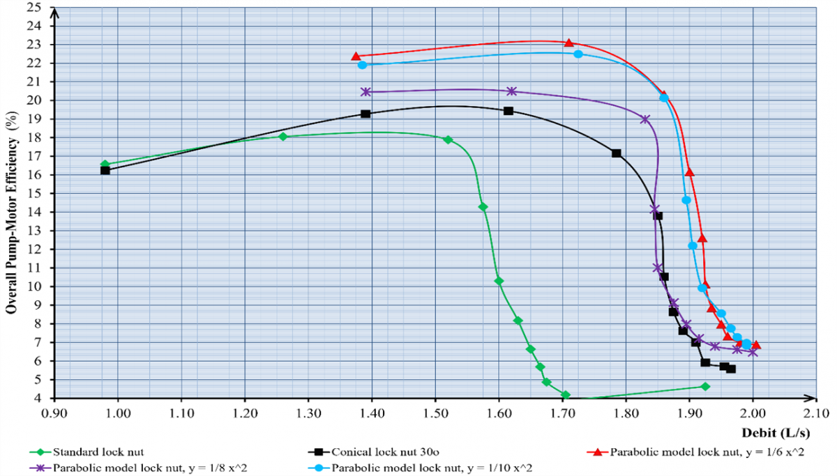
The experimental results demonstrated that the impeller locknut geometry significantly influenced the overall efficiency over the investigated flow-rate range (Figure 5 and Table 3). The efficiency was calculated based on the electrical input power, inherently including motor and mechanical losses. The maximum overall pump-motor efficiency observed was 23.20% for the y = 1/6 x² profile at a discharge of 1.65 L s⁻¹. This relatively low efficiency is characteristic of small-capacity pumps (400 W rating) where electrical and mechanical motor losses constitute a significant portion of the energy balance. The conventional impeller locknut (standard) achieved a peak pump-motor efficiency of 19.35%. The parabolic configuration provided a 3.85 percentage-point improvement.
Figure 5. Comparison of the experimental overall pump-motor efficiency-discharge (η-Q) curves for centrifugal pumps fitted with different impeller locknut geometries
Table 3. Experimental overall pump-motor efficiency (η) measured at different discharge rates
|
Discharge (Q) |
Overall Pump-Motor Efficiency (h) |
||||
|
Standard |
Conical 30o |
Parabolic, y = 1/6 x2 |
Parabolic, y = 1/8 x2 |
Parabolic, y = 1/10 x2 |
|
|
L s⁻¹ |
% |
% |
% |
% |
% |
|
1.90 |
6.10 |
7.30 |
16.20 |
7.75 |
13.70 |
|
1.85 |
5.85 |
13.80 |
20.70 |
17.00 |
20.60 |
|
1.80 |
5.60 |
16.75 |
22.10 |
19.55 |
21.90 |
|
1.75 |
5.40 |
17.90 |
22.80 |
20.00 |
22.35 |
|
1.70 |
5.65 |
18.65 |
23.15 |
20.20 |
22.55 |
|
1.65 |
8.00 |
19.20 |
23.20 |
20.40 |
22.55 |
|
1.60 |
11.50 |
19.50 |
23.10 |
20.55 |
22.45 |
|
1.55 |
18.30 |
19.65 |
22.95 |
20.60 |
22.35 |
|
1.50 |
19.20 |
19.65 |
22.75 |
20.55 |
22.20 |
|
1.45 |
19.35 |
19.55 |
22.60 |
20.50 |
22.05 |
|
1.40 |
18.06 |
19.35 |
22.45 |
20.45 |
21.90 |
This improvement may be associated with reduced inlet hydraulic losses resulting from the streamlined impeller locknut geometry. Previous numerical and experimental studies have suggested that streamlined inlet geometries can reduce form drag and incidence losses, thereby improving pump efficiency [20, 21]. The modified impeller locknuts widened the operating range, maintaining high efficiency, suggesting more stable hydraulic performance beyond the BEP.
The conventional impeller locknut exhibited a sharp efficiency degradation beyond the BEP, dropping to 11.50% at a discharge of 1.60 L s⁻¹. This rapid deterioration indicates progressive internal flow instability at higher discharges. The degradation may be associated with boundary-layer separation and intensified internal recirculation around the impeller hub, which can increase hydraulic losses.
3.3 Effect on hydraulic power and electrical power consumption
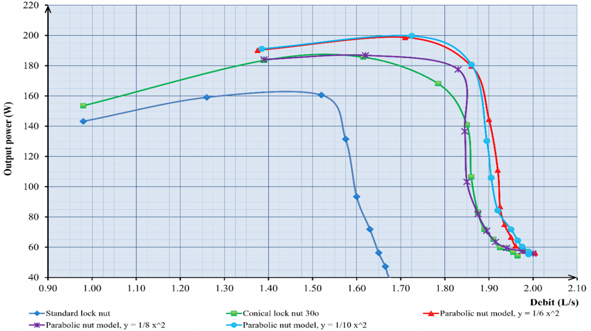
The effect of impeller locknut geometry modification cannot be evaluated solely from changes in pump head and overall pump-motor efficiency. The hydraulic power delivered by the pump and the corresponding electrical power required by the driving motor must also be examined because these parameters collectively reflect the overall effectiveness of energy conversion. The input power curves (Figure 6) and output power curves (Figure 7) showed that modifying the impeller locknut geometry altered the energy distribution from the moment the fluid entered the impeller eye until energy transfer occurred within the impeller passages.
Figure 6. Comparison of the experimental input power-discharge (Pin-Q) characteristics for five impeller locknut configurations
Figure 7. Comparison of the experimental output power-discharge (Pout-Q) performance curves for five impeller locknut configurations
Previous numerical studies have suggested that conical and parabolic inlet geometries reduce form drag and consequently decrease local pressure losses around the impeller eye. Although neither the drag coefficient nor the local pressure distribution was measured directly in the present study, the higher hydraulic output and pump head obtained with the modified impeller locknut configurations are consistent with these previously reported flow mechanisms. This trend was reflected in the output power characteristics, where all modified impeller locknut configurations maintained higher hydraulic power than the conventional impeller locknut over the medium-to-high discharge range. Accordingly, the experimental observations should be interpreted as indirect evidence supporting these previously reported hydrodynamic mechanisms rather than as direct measurements of the internal flow field.
At discharges between 1.60 and 1.80 L s⁻¹, the conventional configuration began to exhibit a noticeable reduction in energy transfer capability. The hydraulic output power decreased to below 100 W, indicating that a considerable portion of the shaft mechanical energy was dissipated through hydraulic losses that may be associated with vortex formation, as reported in previous CFD investigations, flow separation, and recirculation around the impeller eye. In contrast, the modified impeller locknut configurations maintained output power above 160 W until the discharge approached 1.85 L s⁻¹. These results indicate that improving the inlet geometry not only increased the developed head but also preserved the impeller's capability to transfer energy under near-maximum loading conditions.
This behavior is consistent with flow characteristics reported in previous CFD investigations of nose-cone integration in centrifugal flow systems. A streamlined nose-cone profile produces a smoother pressure gradient around the hub, suppressing boundary-layer separation before the flow enters the impeller passages. The resulting reduction in wake formation and inlet turbulence decreases energy dissipation that would otherwise be converted into turbulent kinetic energy, thereby increasing the fraction of mechanical energy converted into useful hydraulic power [22-24].
The input power characteristics, however, exhibited a more complex response. At low discharges, the conventional impeller locknut required the lowest electrical power because the hydraulic loading acting on the impeller remained relatively small. As the discharge increased, the electrical power demand became increasingly unstable, reflecting the development of inlet flow disturbances and pressure fluctuations around the impeller eye [19, 25].
A different trend was observed for the 30° conical impeller locknut. Although this configuration generated higher hydraulic power than the conventional design, its electrical power consumption increased substantially, reaching approximately 1020 W at a discharge of 1.85 L s⁻¹. This observation suggests that the increased electrical power requirement may indicate that the hydraulic improvement was not fully accompanied by comparable mechanical stability. The relatively abrupt geometric transition of the conical profile may have produced a less uniform pressure distribution around the impeller hub. This condition could increase radial and axial hydraulic forces and, consequently, mechanical loading on the shaft and bearings. These effects were not directly measured in the present study.
By comparison, the parabolic impeller locknut configurations exhibited considerably more stable operating characteristics. Throughout the tested flow-rate range, the electrical power consumption remained within 870–895 W, without significant fluctuations. This stable response may indicate more stable hydraulic loading around the impeller eye, although pressure oscillations were not directly measured. A more uniform pressure field may have reduced hydraulic force imbalance, thereby potentially reducing radial and axial loading on the rotor assembly.
The observed hydraulic stability may have implications for mechanical loading and pump reliability; however, these effects were not directly evaluated in the present study. During operation, the rotor is subjected to combined torsional, radial, and axial loads that continuously vary with discharge. An uneven pressure distribution inside the pump casing increases shaft deflection, raises bearing loads, and accelerates the accumulation of cyclic stresses at the impeller locknut thread. Previous studies on impeller locking systems have identified threaded connections as one of the most critical locations for fatigue failure during long-term operation.
The observed performance may be explained by two complementary mechanisms. First, its lower aerodynamic resistance may have promoted a more uniform inlet flow, thereby reducing the amplitude of unsteady hydraulic forces acting on the impeller. Second, the reduction in pressure fluctuations may have reduced vibration excitation throughout the rotor-bearing system. Lower dynamic loading may have reduced bearing friction losses, contributing to a more stable electrical power requirement across the operating range.
The advantages of the parabolic configurations became even more pronounced at high discharges (Q > 1.85 L s⁻¹). Under these operating conditions, the conventional impeller locknut experienced a marked deterioration in performance because of intensified turbulence, wake development, and an increased tendency for cavitation near the impeller eye. In contrast, the parabolic impeller locknut maintained continuous flow into the impeller passages, suggesting delayed deterioration of the inlet flow compared with the conventional configuration. This hydrodynamic stability not only sustained higher hydraulic power output but also maintained electrical power consumption within a relatively narrow operating range. These findings suggest that a simple modification of the impeller locknut geometry can improve hydraulic energy transfer while potentially contributing to more stable pump operation, without requiring any alteration to the primary impeller design.
3.4 Hydrodynamic mechanisms of flow improvement
Internal flow fields were not directly visualized in this study. The measured improvements in head and efficiency are interpreted through flow mechanisms reported in previous numerical and experimental investigations. The performance differences between the conventional and parabolic impeller locknut originate from how each geometry influences the inlet flow conditions prior to impeller entry.
Previous CFD studies suggest that this geometry may promote flow separation and the formation of a wake region immediately downstream of the locknut. The resulting recirculation zone is likely to reduce the effective flow area entering the blade passages, producing a less uniform inlet velocity distribution and potentially increasing incidence losses.
Previous numerical investigations have suggested that streamlined nose-cone geometries reduce form drag and maintain flow attachment over a longer distance. Consequently, the improved hydraulic performance observed in the present study may be associated with weaker wake development and a more uniform inlet velocity distribution. Such flow characteristics have been reported to reduce hydraulic energy dissipation through turbulent kinetic energy production, although these mechanisms were not directly verified in the present experiments.
The smoother hydraulic performance obtained with the parabolic profiles may indicate improved resistance to cavitation inception. Because cavitation characteristics were not directly measured, this interpretation should be regarded as a possible explanation supported by previous experimental and numerical studies. Recent visualization experiments have shown that optimizing impeller inlet parameters can reduce vortex regions and lower the critical cavitation number [8, 10]. The relatively stable efficiency and power characteristics observed in the present study are consistent with these findings, although no direct evidence of local pressure distribution or cavitation behaviour was obtained. Future investigations incorporating flow visualization, pressure measurements, and Net Positive Suction Head (NPSH) testing are required to validate these mechanisms experimentally.
3.5 Comparison with previous experimental and numerical studies
The experimental findings were interpreted in relation to flow mechanisms reported in previous studies of centrifugal-pump inlet geometry. Accordingly, the experimental results obtained in the present study are compared with previous experimental and numerical investigations focusing on the optimization of centrifugal pump impeller inlet geometry. This comparison provides a broader perspective on the effectiveness of the proposed impeller locknut modification in improving hydraulic performance without requiring substantial alterations to the impeller design.
Previous studies have primarily improved centrifugal pump performance through modifications to the impeller geometry, including the incorporation of inducers, the addition of splitter blades, adjustments to the hub inclination angle (HIA), and the redesign of the impeller inlet profile. These approaches generally enhanced suction performance and reduced cavitation susceptibility; however, they required permanent modifications to the impeller, resulting in increased manufacturing costs and design complexity. In contrast, the impeller locknut modification proposed in this study alters only the geometry of the impeller fastening component while preserving the original blade configuration and pump casing.
The performance improvement observed in the present study follows trends reported in several CFD-based investigations of streamlined impeller inlet geometries. Previous studies on the integration of a nose cone in centrifugal blowers reported that streamlining the inlet contour reduced the form drag coefficient by approximately 61.8% while increasing the effective flow area by more than 76%. These geometric improvements reduced the stagnation region upstream of the hub and promoted a more uniform velocity distribution toward the impeller eye. The observed performance improvement is consistent with a similar mechanism, where the parabolic impeller locknut increased the pump head by 11.27% at a discharge of 1.40 L s⁻¹ while simultaneously increasing the maximum overall pump-motor efficiency to 23.20%, without modifying the impeller blade geometry [26, 27].
Optimization strategies based on inducer installation exhibit different hydraulic characteristics. Previous investigations reported that inducers improve suction capability and reduce the Net Positive Suction Head Required (NPSHr), allowing pumps to operate more stably under cavitation-prone conditions [28]. Nevertheless, the additional component increases the wetted surface area, which consequently raises frictional losses. Several studies reported reductions in overall pump-motor efficiency ranging from approximately 1% to 2.5%, particularly near the design operating condition. Such behavior is not observed in the present study. Instead, the parabolic impeller locknut preserves, and in some operating conditions improves, overall pump-motor efficiency because the geometric modification is applied to a component that originally obstructs the incoming flow rather than to the primary energy-transfer elements of the impeller.
These observations indicate that improving the inlet flow characteristics does not necessarily require extensive redesign of the impeller. Reducing the localized flow obstruction at the center of the inlet may improve the pressure distribution before the fluid enters the blade passages. These results suggest that inlet-flow conditioning can provide a measurable contribution to pump hydraulic performance without requiring modification of the primary blade geometry.
The findings of this study are also closely aligned with previous investigations on HIA and hub-cutting configurations. Numerical simulations have demonstrated that variations in hub inclination suppress secondary vortex formation, improve pressure distribution, and reduce entropy generation within the impeller. Despite these hydraulic benefits, implementing such modifications requires redesigning the hub profile and manufacturing a new impeller casting. Consequently, these approaches are more appropriate during the product design stage than for upgrading pumps already in service.
The approach proposed in the present study offers a considerably simpler alternative. Replacing the conventional impeller locknut with a parabolic profile may provide a similar inlet-flow-conditioning effect by reducing flow separation near the inlet and smoothing the transition of the incoming flow toward the hub. This similarity in flow behavior is reflected by the improvements in pump head and overall pump-motor efficiency, despite the substantially smaller geometric modification compared with complete hub redesign.
From a manufacturing perspective, the proposed impeller locknut modification provides practical advantages. The modified component can be fabricated using conventional turning processes without changing either the impeller dimensions or the pump casing. Consequently, implementation costs remain relatively low, while installation can be carried out on existing pumps without permanent modifications to the hydraulic system. This characteristic contrasts with inducer installation or complete impeller redesign, both of which require replacement of major rotating components and subsequent rotor rebalancing.
Beyond hydraulic performance, previous studies have also associated the geometry of impeller fastening components with the mechanical stability of rotating assemblies. A more streamlined profile promotes a more uniform pressure distribution around the impeller hub, thereby reducing fluctuations in radial hydraulic forces. This condition is expected to decrease cyclic loading on both the bearings and the threaded impeller connection. Although radial force and shaft vibration were not directly measured in the present study, the smoother head, efficiency, and power curves obtained with the parabolic impeller locknut suggest a more stable hydrodynamic load distribution throughout pump operation than that observed with the conventional configuration.
Compared with previously published optimization strategies, the proposed impeller locknut modification offers an attractive balance between hydraulic performance improvement and implementation complexity. Most existing approaches require substantial modifications to the impeller geometry, whereas the present study improves performance by altering only a small component located at the center of the inlet flow path. Despite the limited geometric modification, its influence on inlet flow development is sufficient to increase pump head, maintain higher overall pump-motor efficiency at elevated discharges, and improve the overall power consumption characteristics.
The experimental results demonstrated that impeller locknut geometry has a measurable influence on the hydraulic performance of the tested radial-flow centrifugal pump. The parabolic configurations generally produced higher pump head and overall pump–motor efficiency than the conventional geometry, although the optimum profile depended on the operating condition and performance metric.
Among the tested configurations, the y = 1/10 x2 profile provided the highest pump head at the design discharge, whereas the y = 1/6 x2 profile achieved the highest overall pump–motor efficiency. The parabolic configurations also maintained more stable hydraulic and electrical power characteristics at elevated discharges than the conventional locknut. These findings indicate that streamlining the impeller locknut can improve inlet-flow conditioning without requiring modification of the primary impeller blades or pump casing.
The study was limited to external hydraulic performance measurements. Internal flow structures, pressure distributions, cavitation behavior, vibration characteristics, and NPSH performance were not directly measured. Accordingly, the proposed hydrodynamic mechanisms should be regarded as interpretations supported by previous studies rather than as direct experimental observations. Future investigations should incorporate flow visualization, pressure-pulsation measurements, vibration analysis, and NPSH testing to validate the mechanisms responsible for the observed performance differences.
The authors would like to express their sincere appreciation to the Mechanical Engineering Laboratory, Cenderawasih University, for providing the experimental facilities and technical support throughout this study. The authors also gratefully acknowledge the assistance of all laboratory staff who contributed to the preparation, testing, and data acquisition processes. Their support was invaluable in ensuring the successful completion of the experimental work.
[1] Hermez, M.Y., Jawad, B., Liu, L.P., Abro, S. (2018). Optimization of curved spacer prototype design for flow improvement in centrifugal pump impeller. In ASME 2018 International Mechanical Engineering Congress and Exposition, Pittsburgh, Pennsylvania, USA, p. V007T09A074. https://doi.org/10.1115/IMECE2018-87075
[2] Wang, C.Y., Wang, F.J., An, D.S., et al. (2021). A general alternate loading technique and its applications in the inverse designs of centrifugal and mixed-flow pump impellers. Science China Technological Sciences, 64(4): 898-918. https://doi.org/10.1007/s11431-020-1687-4
[3] Matlakala, M.E., Kallon, D.V.V., Simelane, S.P., Mashinini, P.M. (2019). Impact of design parameters on the performance of centrifugal pumps. Procedia Manufacturing, 35: 197-206. https://doi.org/10.1016/j.promfg.2019.05.027
[4] Ye, W.X., Zhuang, B.T., Wei, Y.L., Luo, X.W., Wang, H. (2024). Investigation on the unstable flow characteristic and its alleviation methods by modifying the impeller blade tailing edge in a centrifugal pump. Journal of Energy Storage, 86(Part B): 111358. https://doi.org/10.1016/j.est.2024.111358
[5] Ji, L.L., Li, S., Li, W., et al. (2023). Study on passive suppression method of rotating stall in mixed-flow pump: Using different impeller rim structures. Proceedings of the Institution of Mechanical Engineers, Part A: Journal of Power and Energy, 237(5): 965-984. https://doi.org/10.1177/09576509231153304
[6] Yang, Y., Chen, X.H., Su, D., et al. (2024). Investigations on the energy characteristics and internal flow dynamics of a mixed-flow pump considering of inlet pre-rotation at off-rated flow conditions. Iranian Journal of Science and Technology, Transactions of Mechanical Engineering, 48(4): 1973-1986. https://doi.org/10.1007/s40997-024-00752-3
[7] Luo, X.W., Zhang, Y., Peng, J.Q., Xu, H.Y., Yu, W.P. (2008). Impeller inlet geometry effect on performance improvement for centrifugal pumps. Journal of Mechanical Science and Technology, 22(10): 1971-1976. https://doi.org/10.1007/s12206-008-0741-x
[8] Riahinezhad, L., Nooraeen, A., Mohammadkhah, M., Hassani, K. (2026). Coupled computational fluid dynamics–aeroacoustic analysis of fan noise: Influence of rotational speed, inflow, and blade serrations. Power Engineering and Engineering Thermophysics, 5(1): 1-17. https://doi.org/10.56578/peet050101
[9] Hou, D.H., Li, T.X., Lu, H.Z., Yao, Z.F., Xiao, R.F., Li, S.K. (2024). Visual experimental study on cavitation performance of double-suction centrifugal pump. Journal of Physics: Conference Series, 2707(1): 012043. https://doi.org/10.1088/1742-6596/2707/1/012043
[10] Li, W., Pu, W., Ji, L.L., Zhang, X., He, X.R. (2024). Hydraulic structure optimization of centrifugal pump based on orthogonal test. In the 17th Asian International Conference on Fluid Machinery, Zhenjiang, China, 2707(1): 012056. https://doi.org/10.1088/1742-6596/2707/1/012056
[11] Han, J., Xue, S., Zuo, H., et al. (2024). Study of cavitation characteristics and optimal design of hydraulically suspended micro-pump. Journal of Engineering Thermophysics, 46(1): 232-238.
[12] Zhang, H., Zhang, D.S., Zhang, G.J., Ye, X.Y., Cao, P.Y. (2025). Effect of cavitation structures and flow rates on pressure pulsation in the inducer: An experimental investigation. International Journal of Multiphase Flow, 190: 105272. https://doi.org/10.1016/j.ijmultiphaseflow.2025.105272
[13] Pourabdollah, D., Sobhani, P., Najafi, A.F. (2026). Investigation of inducer geometry variations on centrifugal pump hydraulic performance: Numerical approach. International Journal for Numerical Methods in Fluids, 98(4): 529-545. https://doi.org/10.1002/fld.70049
[14] Li, X.J., Yuan, S.Q., Pan, Z.Y., Li, Y., Liu, W. (2013). Dynamic characteristics of rotating stall in mixed flow pump. Journal of Applied Mathematics, 2013: 104629. https://doi.org/10.1155/2013/104629
[15] Cui, B.L., Miao, X.X. (2026). Influence of hub-cutting impellers on energy loss in a high-speed centrifugal pump. Engineering Computations, 43(2): 504-520. https://doi.org/10.1108/EC-10-2024-0951
[16] Park, J., Yeom, J., Baeck, S., Lee, S., Park, J.Y. (2025). A numerical analysis of flow dynamics improvement in a blower via simple integration of bell mouth and nose cone structures. Energies, 18(7): 1830. https://doi.org/10.3390/en18071830
[17] Kuang, R.F., Zhang, Z.M., Wang, S.L., Chen, X.P. (2021). Effect of hub inclination angle on internal and external characteristics of centrifugal pump impellers. AIP Advances, 11(2): 025043. https://doi.org/10.1063/5.0038109
[18] Zhang, L.W., Wang, X., Wu, P., Huang, B., Wu, D.Z. (2023). Optimization of a centrifugal pump to improve hydraulic efficiency and reduce hydro-induced vibration. Energy, 268: 126677. https://doi.org/10.1016/j.energy.2023.126677
[19] Chen, X.B., Yang, B.W., Zhang, R.H., Guo, G.Q., Yang, J.H. (2024). Impacts of inlet flow velocity perturbation uncertainty for centrifugal pumps on hydraulic performance and flow field. Transactions of the Chinese Society of Agricultural Engineering, 40(12): 77-85. https://doi.org/10.11975/j.issn.1002-6819.202312066
[20] Liu, X.D., Li, Y.J., Liu, Z.Q., Yang, W. (2022). Experimental and numerical investigation of stall mechanism in centrifugal pump impeller. Journal of Applied Fluid Mechanics, 15(3): 927-941. https://doi.org/10.47176/JAFM.15.03.33165
[21] Xu, Y., Tan, L., Cao, S.L., Qu, W.S. (2017). Multiparameter and multiobjective optimization design of centrifugal pump based on orthogonal method. Proceedings of the Institution of Mechanical Engineers, Part C: Journal of Mechanical Engineering Science, 231(14): 2569-2579. https://doi.org/10.1177/0954406216640303
[22] Zhou, S.H., Lin, P.F., Zhang, W., Zhu, Z.C. (2020). Evolution characteristics of separated vortices and near-wall flow in a centrifugal impeller in an off-designed condition. Applied Sciences, 10(22): 8209. https://doi.org/10.3390/app10228209
[23] Li, X.J., Chen, B., Luo, X.W., Zhu, Z.C. (2020). Effects of flow pattern on hydraulic performance and energy conversion characterisation in a centrifugal pump. Renewable Energy, 151: 475-487. https://doi.org/10.1016/j.renene.2019.11.049
[24] Bai, Y.M., Appiah, D., Tao, Y. (2022). Computational turbulent flow characteristics in a centrifugal pump. AIP Advances, 12(7): 075025. https://doi.org/10.1063/5.0100915
[25] Al-Obaidi, A.R., Shaban, A.H. (2025). Experimental and numerical the effect of cavitation detection on hydraulic performance of the centrifugal pump based on different geometrical configurations. Journal of Engineering Research, 13(4): 3718-3738. https://doi.org/10.1016/j.jer.2024.11.006
[26] El Samanody, M.A., Ghorab, A., Mostafa, M.A.F. (2014). Investigations on the performance of centrifugal pumps in conjunction with inducers. Ain Shams Engineering Journal, 5(1): 149-156. https://doi.org/10.1016/j.asej.2013.07.003
[27] Hawash, S.A.F., El-Gazzar, D.M.S., El-Samanoudy, M.A. (2015). Reliability improvements to centrifugal pump performance in conjunction with inducers, CFD: Comparative study. Journal of Earth Science and Engineering, 5: 296-305. https://doi.org/10.17265/2159-581X/2015.05.004
[28] Mandhare, N.A., Karunamurthy, K., Ismail, S. (2020). Computational investigation of flow over nose cap of closed impeller of mixed flow centrifugal pump. Journal of Pressure Vessel Technology, 142(3): 031701. https://doi.org/10.1115/1.4045727