Messaouda Bedoui*![]() | Abderrahmane Berkani
| Abderrahmane Berkani![]() | Karim Negadi
| Karim Negadi![]() | Fabrizio Marignetti
| Fabrizio Marignetti![]() | Souhil Drias
| Souhil Drias![]()
© 2025 The authors. This article is published by IIETA and is licensed under the CC BY 4.0 license (http://creativecommons.org/licenses/by/4.0/).
OPEN ACCESS
This study focuses on enabling real-time power factor measurement and automatic correction using a smart Arduino UNO R3 system. By continuously monitoring the power factor, the system can engage capacitors to optimize energy consumption and reduce costs. It's important to adhere to safety standards when working with high-voltage circuits. In recent years, many commercial and industrial installations in the country have had large electrical loads, often highly inductive, resulting in a lagging power factor. This can lead to significant penalties imposed by the electricity board. Power factor correction (PFC) addresses this issue. For fixed loads, manual switching of capacitors can be effective; however, for rapidly varying loads, maintaining a high-power factor becomes challenging through manual intervention. This limitation is overcome by using an automatic PFC panel. In this work, the power factor is controlled using Arduino with a microcontroller to activate the necessary capacitors for reactive power compensation, bringing the power factor closer to unity.
power factor correction, automatic switching, Arduino, Atmega328 microcontroller, reactive compensation
Power factor (PF) is the ratio of real power to apparent power in an electrical circuit, indicating the efficiency of power consumption. A PF close to one signifies optimal performance, while lower values indicate inefficiencies. Automatic correction of the power factor enhances system efficiency and reduces energy costs. Studies have shown that power factor correction is beneficial for improving the active power delivered to industrial installations. In industrial settings with inductive loads, the power factor tends to lag. When it drops below a certain threshold (usually 0.97), utility companies levy penalties on the consumer. Therefore, maintaining the power factor within acceptable limits is crucial. An automatic power factor correction device is designed to monitor the power factor from line voltage and current, calculate the necessary adjustments, and activate the capacitor banks connected to the load to achieve the desired power factor.
Pan and Pen [1] used active filters for power factor correction, providing a unique solution to the problem. The main advantage of this method is its effectiveness in improving the power factor. However, a significant drawback is that active filters lack precise cutoff frequencies and do not include a controller, resulting in a manual rather than automatic system. In contrast, Anant Kumar Tiwari's research focused on using the 89C52 microcontroller to measure and corrects the power factor.
The key benefit of this approach is that it presents an optimal method for measuring power factor in systems. However, a significant drawback is the increased response time of the microcontroller [2]. Khan and Owais [3] employed a precision rectifier, an EXOR gate, and an Arduino board in combination with inductive and capacitive loads to improve power factor correction. The main advantage of their method is its capability to measure voltage and current values, effectively addressing power factor issues and displaying the corrected values. A notable limitation, however, lies in the measurement process itself. Ayaz et al. [4] conducted an in-depth study aimed at improving power factor efficiency in industrial systems by implementing an intelligent control strategy for capacitor banks. The approach involves utilizing real-world data gathered from an industrial facility to evaluate the power factor performance, comparing the results before and after the installation of the capacitor banks. Naresh et al. [5] introduced a simple, cost-efficient spontaneous PF correction method for single-phase native loads, utilizing optocouplers and capacitive loads in a unique approach. Prasad et al. [6] recommended PF correction using multiple bypass capacitors to reduce power loss, though their study did not include a cost analysis. Nanda et al. [7] discussed the disadvantages of a lagging PF, its benefits, improvement methods, and future applications, but their findings were not clearly presented. Balamurugan et al. [8] proposed a power factor adjustment model utilizing SEPIC and boost converters, integrating affordable hardware such as the Arduino Uno, relay modules, and Wi-Fi components. Jeevanantham and Muthusundaram [9] described a system using the Internet of Things (IoT) to continuously monitor various parameters of an induction motor and update the data on a webpage.
In the upcoming section, we will describe how power factor improvement works and discuss in detail the methodology and implementation of automatic power factor correction (APFC) used in this system. Section 5 will then present and analyse the results, followed by the conclusion of the study in Section 6.
This paper aims to enhance the power factor in distribution network systems. To achieve this, we plan to implement APFC using Arduino UNO R3 in which ATmega328 as microcontroller. This approach will help correct the power factor, thus enhancing the efficiency and stability of power delivery in three-phase grid systems.
In recent years, the importance of maintaining an optimal power factor in electrical distribution networks has grown due to its impact on energy efficiency and utility costs. Traditional methods of power factor correction (PFC) rely on manual adjustments or static systems, which can be inefficient, costly, and slow to respond to dynamic load conditions. While automated PFC systems have been proposed, many existing solutions still face challenges in real-time adaptability, cost-effectiveness, and scalability for smaller or experimental setups. The research gap in this area lies in the development of a practical, low-cost, and efficient solution that can provide real-time monitoring and automatic correction of power factor in three-phase distribution networks, particularly in environments with varying loads. This study introduces a novel approach using a smart Arduino-based system for automatic power factor detection and correction. By leveraging the Arduino platform, this study provides an affordable and flexible solution that integrates real-time data collection, phase angle measurement, and capacitive reactive power compensation to dynamically adjust the power factor. The novelty of this research lies in its practical application of Arduino for automatic PFC in three-phase systems, offering an accessible solution for both small-scale and industrial applications, with the potential to improve energy efficiency and reduce operational costs.
Apparent power, also known as the total power supplied by the utility company, consists of two components: active power and reactive power. Active power, measured in kilowatts (kW), is the power that drives equipment and performs useful work. Reactive power, measured in kilovolt-amperes reactive (kVAR), is needed to create the magnetic fields required for operating inductive devices such as AC motors, transformers, and inductive furnaces. Active power represents the conversion of electrical energy into other forms of energy, such as heat or mechanical energy [10, 11].
2.1 Power factor
Power factor (PF) is the ratio of real power (P) to apparent power (S) in an AC electrical circuit. It's a measure of how effectively electrical power is being used.
$P=\sqrt{3} \cdot U \cdot I \cdot \cos \varphi$ (1)
where,
P: Active power.
U: Phase-to-phase voltage.
I: Current.
φ represents the phase angle between the voltage and current. The term "cosφ" is referred to as the power factor. Power factor is the ratio of the real power (KW) to the apparent power (KVA) drawn by an electrical load, where KW is the actual power consumed and KVA is the total apparent power. It serves as an indicator of how efficiently the electrical current is being converted into useful work and is particularly useful in assessing the impact of load current on the overall efficiency of the supply system. The concept of an ideal power factor is 1 (or 100%), which indicates that all the power supplied is being used efficiently for useful work.
2.2 Causes OF LOW POWER FACTOR
2.2.1 Inductive loads
Low power factor is often caused by inductive loads such as motors, transformers, and fluorescent lighting. These devices cause a lag between the voltage and current waveforms, leading to a phase shift.
2.2.2 Capacitive loads
In some cases, capacitive loads can also affect power factor, but less commonly in typical industrial settings.
2.3 Impact of low power factor
2.3.1 Wasted energy
Low PF means more energy is wasted as reactive power (Q), which doesn’t contribute to useful work but still has to be generated and transmitted.
2.3.2 Higher energy costs
Utility companies may impose penalties for low PF, leading to higher electricity costs.
2.3.3 Inefficient equipment operation
Electrical equipment may experience overheating, and transformers and generators may need to be oversized.
2.4 Role of power factor correction
Power Factor Correction (PFC) aims to reduce the phase difference between voltage and current, improving the power factor and bringing it closer to 1. This reduces wasted energy and enhances system efficiency. PFC compensates for the inductive reactive power (Q) by introducing capacitive reactance (Qc) into the system, which cancels out the inductive reactance.
2.5 Calculation of power factor using theory
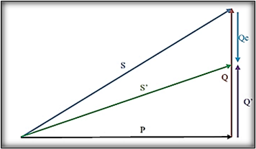
The apparent power is always greater than the active power in inductive loads and varies depending on the type of equipment used. It is measured in kilovolt-amperes (kVA) and consists of both working power (kW) and reactive power (kVAR). Inductive receivers, like motors and transformers, consume reactive energy, while capacitive receivers (capacitors) produce reactive energy. Compensating an installation involves adding a source of reactive compensation energy to improve the power factor of the system, enhancing the overall efficiency of the installation. Figure 1 illustrates the vector representation of this compensation process [11-14].
Figure 1. Diagram of power compensation
The benefits of power factor correction include:
Reduced Utility Power Bills: Improved efficiency leads to lower electricity costs.
Increased System Capacity: The ability to handle additional loads without the need for system upgrades.
Improved System Operating Characteristics (Increased Voltage): Enhanced voltage stability throughout the system.
Improved System Operating Characteristics (Reduced Line Losses): Lower energy losses during transmission, resulting in greater overall efficiency.
The power triangle method enables us to calculate the reactive power of the compensation capacitor and, consequently, its capacity. The reactive power for compensation, QC, can be expressed as a function of the angles $\varphi$ and $\varphi^{\prime}$.
$Q_c=P\left(\tan \varphi^{\prime}-\tan \varphi\right)$ (2)
where,
P: Active power of the installation.
$\varphi$: Phase angle before compensation.
$\varphi^{\prime}$: Phase angle after compensation.
QC: Reactive power produced by a capacitor having at its terminals the voltage U, in a three-phase system is:
$Q_c=3 . C . \omega \cdot U^2$ (3)
where,
U: Phase-to-phase voltage.
C: Capacitance.
$\omega$: Network pulsation rad/s.
$\omega=2 . \pi . \mathrm{f}$ (4)
2.6 Calculation of compensated capacitor units
To compensate for the reactive energy, we place a capacitor in parallel and upstream of the load, and then we dimension the capacitor to obtain:
$\cos \varphi=1$ (5)
A capacitor of capacity $C$, presenting at its terminals a voltage $U$ of pulsation $\omega$ provides a reactive power can be determined using Eq. (6):
$Q_C=-C \omega \times U^2$ (6)
The reactive power before compensation is given by the Eq. (7):
$Q=P \times(\tan \varphi)$ (7)
The reactive power after compensation is given by the Eq. (8):
$Q^{\prime}=P \times(\tan \varphi)$ (8)
The compensation reactive power is given by the difference between Eqs. (7) and (8).
$Q c=Q-Q^{\prime}$ (9)
So,
$Q c=P \times\left(\tan Q-\tan Q^{\prime}\right)=-C \omega \times U^2$ (10)
$C=\frac{Q c}{U^2 \times \omega}$ (11)
Recognising the significance of power factor correction in electrical installations and the various techniques available, we have developed a power factor corrector for electrical systems. Our research pointed us towards an Arduino-based solution, which is not only straightforward and effective but also offers several advantages.
Figure 2 illustrates that the principle of the automatic power factor detection and correction circuit involves monitoring the power factor using a microcontroller integrated into the Arduino UNO board via the uploaded code. The voltages and currents are acquired from the main AC line through current and voltage sensors. The microcontroller reads these current and voltage values and utilises this data in its algorithm to calculate the necessary capacitor size for power factor correction while also monitoring the load behaviour based on the load current.
In the event of a poor power factor, the microcontroller sends a signal to the relay switching unit to activate the required capacitor. The actions undertaken by the microcontroller to rectify the low power factor including the selection of the appropriate capacitor and continuous load monitoring are displayed on an LCD screen.
Figure 2. Schematic diagram of automatic power factor correction using Arduino UNO
This section focuses on an experimental study aimed at improving the power factor. To achieve this, an experimental setup was established within the Electrical Network laboratory of the Electrical Engineering Department at IBN KHALDOUN University in Tiaret. The study specifically examines the parallel compensation of reactive energy and the methods used to correct the power factor.
We use in this part the following materials:
•Three-phase power supply.
•Transmission line.
•Measuring devices (ammeter, voltmeter).
•Arduino UNO card with an ATmega328 microcontroller.
•Sensors (current and voltage).
•Relays.
•Loads (resistances, inductances, capacities).
•Three-phase electrical network analyzer CA 8331.
4.1 Voltage sensor ZMPT101B
The ZMPT101B voltage sensor shown in Figure 3 is an AC type voltage sensor based on an integrated voltage transformer and it is characterized by:
•High accuracy.
•Good reliability.
•Wide measuring range (0-250 AC).
•Very easy to use and build.
•A potentiometer to adjust the ADC output.
The integrated voltage sensor reduced the signal to 2.5 V (peak), and then a 2.5 V offset was added to shift the signal to a positive level detectable by the ESP32, resulting in a peak of 5 V [15].
Figure 3. Voltage sensor
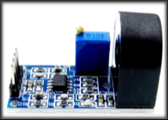
4.2 Current sensor ZMCT103C
The module is equipped with ZMCT103C series high-precision small current transformers and high-precision operational amplifier circuits. This enables accurate sampling and effective signal compensation, allowing for the acquisition of AC signals of up to 5A. The output analogue signal is adjustable; with the desired output voltage configured using a potentiometer, enabling amplification ratios ranging from 0 to 100 times. It's important to note that the maximum output voltage (OUT) will not exceed half of the supply voltage (½ VCC) (Figure 4) [15].
Figure 4. Current sensor
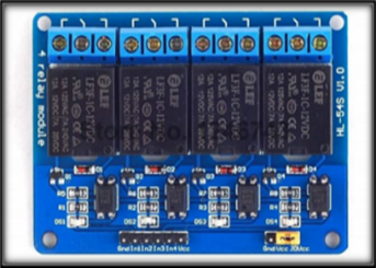
4.3 Relay
The relay shown in Figure 5 is a 4-channel low-level relay interface board that operates at 5 V. Each channel needs a drive current of 15-20 mA, allowing it to control various high-current devices and equipment. The board contains high-current relays that can handle AC loads up to 250 V at 10 A or DC loads up to 30 V at 10 A. It has a standard interface for direct control by a microcontroller. Additionally, this module is optically isolated from the high-voltage side to ensure safety and to prevent ground loops during interfacing with the microcontroller [12, 13, 15].
Figure 5. Four-channel relay
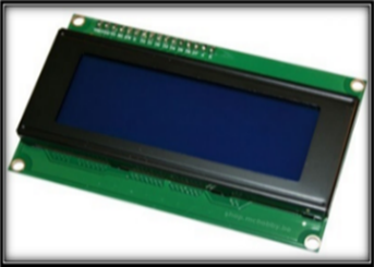
4.4 LCD display 20x4 with I2C module
This type of crystal display shown in Figure 6 is highly favoured for its affordability and ease of programming. In our project, we will utilise the LCD2004 Crystal Display, which features four lines and 20 columns and is powered by the Hitachi HD44780 driver. The pins of this display are as follows [12]:
Register Select (RS): This pin determines whether data is written to the data register or the instruction register.
Read/Write (R/W): This pin indicates the mode of operation, specifying whether the display is in read or write mode.
Enable Pin: Activating this pin allows data to be written to the LCD. Data Pins (D0-D7): These pins are used to transmit data to the display's registers.
This configuration facilitates efficient communication with the display, enabling smooth operation within our project.
Figure 6. 20×4 LCD display
4.5 Description of the Arduino UNO R3 board
Arduino shown in Figure 7 is a family of open-source microcontroller boards that originated in Italy in 2005. These boards are designed with a straightforward input/output interface and a development environment that closely resembles the C programming language. The first stable version of the Arduino board incorporates all the features typical of a classic microcontroller while offering exceptional ease of use. It utilizes an ATmega328P chip operating at a clock speed of 16 MHz. The board is equipped with 32 KB of flash memory for storing programs, 2 KB of SRAM (static random-access memory), and 1 KB of EEPROM (electrically erasable programmable read-only memory) for data storage [8-16]:
Figure 7. Description of the Arduino UNO R3
4.5.1 Arduino's role in power factor correction (PFC)
Arduino can be used to measure the real-time power factor by monitoring voltage, current, and phase angle using sensors such as current and voltage sensors. With the appropriate sensors and actuators, the Arduino can be programmed to control the switching of capacitors, automatically adjusting the power factor based on load conditions. With Arduino, you can get immediate feedback on the power factor, helping to identify inefficiencies or changes in the load. This real-time data is essential for making quick adjustments to improve efficiency.
Arduino boards, such as the Arduino UNO, are inexpensive compared to traditional power factor correction equipment and industrial controllers. This makes Arduino an accessible solution for small-scale or experimental power factor correction projects, especially in educational or DIY contexts. Arduino is widely available, and its popularity means that there are plenty of resources, tutorials, and community support available for integration into PFC systems.
One of the main benefits of using Arduino for PFC is its ability to automate the correction process. Based on the real-time power factor measurement, the Arduino can trigger the activation or deactivation of capacitors to adjust the system’s power factor dynamically. This reduces the need for manual intervention, also can respond to load fluctuations and automatically adjust the capacitor bank to ensure that the power factor remains at an optimal level, avoiding penalties from utilities due to low power factor.
By automating the power factor correction process, Arduino ensures that the system operates at the most efficient power factor possible, reducing wasted energy. This can lower electricity bills for users, especially in industrial or commercial applications where energy costs are high. In addition to the initial low cost of the Arduino system, using Arduino for PFC minimizes the need for expensive power factor correction equipment and manual labor for adjustments. For small businesses or homes, Arduino-based power factor correction systems provide a cost-effective and easy-to-implement solution to reduce electricity costs due to poor power factor. In industrial settings, Arduino can be used to automate the PFC process in systems with varying loads, reducing operational costs and improving system efficiency.
In summary, Arduino for power factor correction provides flexibility, real-time monitoring, automation, and a cost-effective solution, making it suitable for both small-scale and larger applications. Its adaptability and ease of use make it ideal for experimental setups, educational purposes, and commercial or industrial systems [17, 18].
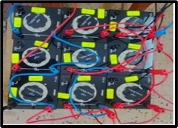
4.6 Capacitor bank
The capacitor bank shown in Figure 8 is made up of multiple identical capacitors connected either in parallel or in series. These banks are often used to reduce unwanted effects, such as power factor lag, in electrical systems. By supplying reactive power, capacitor banks improve power factor and enhance overall system efficiency [19, 20].
Figure 8. Capacitor bank
In the first part, we show how the system behaves without compensation, which means without using capacitors. Figure 9 illustrates how the load is set up in a three-phase network system. To calculate the power factor accurately in real time, we used two sensors: a current sensor to measure the load current and a voltage sensor to monitor the voltage. The smart control unit, which is based on a microcontroller, calculates the phase shift between current and voltage, ensuring that the capacitor stages are used uniformly and optimising power factor correction. An LCD connected directly to the Arduino will display current, voltage, and power factor readings to show various explanatory characteristics.
Figure 9. Project implementation with smart automatic Arduino unit before parallel compensation
5.1 Experimental results and discussion before compensation
In this scenario, the relays are entirely deactivated, meaning that no capacitors will be connected to the electrical installation, allowing us to observe the system before power factor (PF) correction. We utilised a mixed resistive-inductive load with the following specifications: inductance (L) of 1.2 H and resistance (R) of 1000 Ohms.
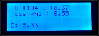
Table 1 and Figure 10 illustrate the various electrical characteristics of this load. It is evident that the phase shift is 56.63°, resulting in a power factor of 0.55. This low power factor indicates inefficiencies in the system that could be addressed through corrective measures.
Table 1. Practical measurements for an ohmic-inductive load before correction
|
P(W) |
Q(Var) |
U(V) |
V(V) |
I(A) |
Cos $\varphi$ |
|
120.6 |
220.1 |
318.7 |
184 |
0.37 |
0.55 |
Figure 10. Electrical characteristics of an ohmic-inductive load before correction
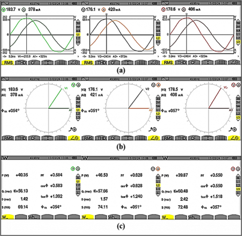
Figure 11. Experimental results: Current and voltage of three-phase load
Figure 12. Experimental results before correction: (a) Phase shift for each phase, (b) Vector diagram, (c) Measured powers and power factor in the three phases
To confirm the obtained result on the LCD, we utilized a three-phase electrical network analyzer CA 833 to record the measurement voltage and current signals, as depicted in Figures 11 and 12.
In Figure 12, the current and voltage signals and vector diagrams display the phase shift between the current and voltage. The load causes a phase shift of 54°, 51°, and 57° for each phase, resulting in power factors of 0.58, 0.62, and 0.55 respectively. This lower power factor leads to the consumption of reactive power for each phase. Given that the power factor is significantly less than unity, it is crucial to add compensation capacitors to address this issue.
5.2 Experimental results and discussion after compensation and correction
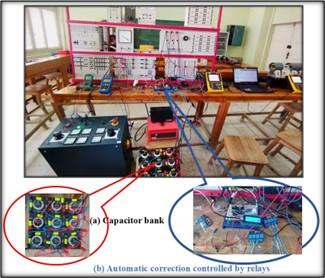
In the test conducted after compensation and automatic power factor correction, the relays are automatically controlled by the Arduino, which calculates the necessary value for correction. The Arduino activates the appropriate relay to close the circuit, thereby connecting the capacitor bank to the electrical network system. These capacitors are specifically designed to enhance the power factor of the system and reduce the amount of non-productive reactive energy circulating within the network.
As illustrated in Figure 13, the capacitor bank is connected in parallel with the load. We utilized three capacitors with values of 1 µF, 2 µF, and 4 µF. When the power factor exceeds 1 due to compensation, the Arduino adjusts the system to bring the power factor as close as possible to 1 without exceeding it. This ensures optimal performance and efficiency in the electrical installation.
Figure 13. Implementation design for investigating parallel compensation with smart automatic Arduino unit
From the measurements in Table 2 and by using Eq. (12), we can determine the theoretical value of the compensation capacitor.
$C=\frac{Q c}{U^2 \times \omega}=\frac{P \times\left(\tan Q-\tan Q^{\prime}\right)}{U^2 \times \omega}=5.73 \mu F$ (12)
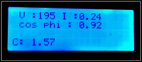
The inclusion of capacitors has led to significant improvements in the electrical system, as demonstrated in Table 3 and Figure 14. There has been a notable decrease in current, indicating a reduced demand for reactive energy and improved efficiency. Active power has also risen, indicating that energy is being used more effectively. The amount of reactive power has decreased significantly, showing the effectiveness of the capacitors in improving the power factor. Additionally, the power factor has substantially improved, approaching the ideal value of one. This improvement results in lower energy losses and increased system efficiency. Overall, these changes demonstrate the effectiveness of using capacitors to compensate for reactive energy, ultimately making the system more cost-effective and reliable.
Table 2. Values of the capacitor theory and measurement
|
Value |
Theory |
By Arduino |
|
C (µF) |
5.72 |
5.33 |
Table 3. Practical measurements for an ohmic-inductive load after correction
|
P(W) |
Q(Var) |
U(V) |
V(V) |
I(A) |
Cos $\varphi$ |
|
143.6 |
83.3 |
337.94 |
195.1 |
0.24 |
0.92 |
Figure 14. Electrical characteristics of an ohmic-inductive load after correction
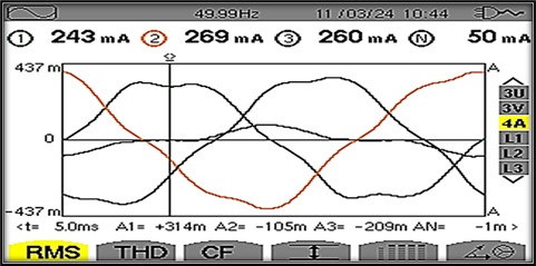
Figure 15. Experimental results: Current and voltage of three-phase load after correction
Same way to confirm the result obtained in value on the LCD, we used a Three-phase electrical network analyzer CA 833 to mount the measurement voltage and current signals as shown in the Figures 15 and 16.
5.3 Comparison analysis
Table 4 summarizes the results obtained before and after the power factor correction. Initially, the measured power factor resulted in cable overloading due to the high current caused by the reactive component, leading to significant additional costs. However, with the implementation of the correction device, a noticeable improvement is evident: the current is reduced, and the power factor is enhanced, effectively eliminating these extra expenses. This improvement is achieved automatically and adaptively, demonstrating the effectiveness of the power factor correction system in optimizing electrical performance and reducing operational costs.
Figure 16. Experimental results after correction: (a) Phase shift for each phase, (b) Vector diagram, (c) Measured powers and power factor in the three phases
Table 4. Recaps the results obtained before and after correction
|
Load |
Voltage U(V) |
Current I (A) |
Active Power P(W) |
Reactive Power Q(Var) |
Cos |
|
Before compensation |
|||||
|
L=1.2 H R=1000Ω |
318.7 |
0.37 |
120.6 |
220.1 |
0.55 |
|
After compensation |
|||||
|
L=1.2 H R=1000 Ω |
337.9 |
0.24 |
143.6 |
83.3 |
0.92 |
There are various strategies used to minimise power losses and energy consumption in three-phase power distribution networks. One effective method involves using systems that automatically adjust reactive power compensation to optimise the power factor in electrical systems. This enhances efficiency and reduces energy usage by inductive loads. Recognising the critical role of power factor correction (PFC) for these loads, this project was initiated.
The capacitor bank is used to counteract the inductive load from equipment that includes motors and transformers. Integrating the capacitor bank into the power supply system has been shown to significantly lower energy consumption compared to systems without it. Studies indicate that adding an appropriately sized capacitor can effectively reduce overall power consumption for consumers.
We want to express our sincere gratitude to everyone who contributed their valuable time and efforts, both directly and indirectly, to the completion of our project as part of our curriculum. We also extend our heartfelt thanks to the electrical engineering department for all the support and resources provided.
[1] Pan, Z., Pen, F.Z. (2005). Power factor correction unit using active series of filter. IEEE Transactions on Power Electronics, 20(1): 148-153. https://doi.org/10.1109/TPEL.2004.839819
[2] Tiwari, A.K. (2014). Power Factor Correction unit using 89C52 microcontroller. International Journal of Engineering Research and Applications, pp. 2248-9622.
[3] Khan, M.B., Owais, M. (2016). Automatic power factor correction unit. In 2016 International Conference on Computing, Electronic and Electrical Engineering (ICE Cube), Quetta, Pakistan, pp. 283-288. https://doi.org/10.1109/ICECUBE.2016.7495239
[4] Ayaz, M., Rizvi, S.M.H., Akbar, M. (2023). Dynamic power factor correction in industrial systems: An automated capacitor bank control approach. In 2023 2nd International Conference on Emerging Trends in Electrical, Control, and Telecommunication Engineering (ETECTE), Lahore, Pakistan, pp. 1-6. https://doi.org/10.1109/ETECTE59617.2023.10396685
[5] Naresh, K., Kumar, T., Sameer, M., Kamsani, S.R. (2020). Arduino-based auto power factor correction using optocouplers and capacitive load banks. Mukt Shabd Journal, 9(5): 3213-3220.
[6] Prasad, M.S.S., Khan, P.K., Kumar, R.V.S., Pandarinadh, K., Srinivas, G. (2020). Automated power factor correction and monitoring system. International Journal of Innovative Technologies, 8(1): 70-74.
[7] Nanda, P., Rathod, S., Halapeti, B., Poojari, D., Math, G., Jalageri, S. (2020). Automatic power factor correction using ATmega328. International Journal of Advances in Engineering and Management, 2(3): 146-149. https://doi.org/10.35629/5252-0203146149
[8] Balamurugan, K., Gowsika, M., Monika, T., Naveen, N. (2021). Power factor correction using SEPIC Dc-Dc converter in industrial motor drives. Journal of Interdisciplinary Cycle Research, 9(5): 21-28.
[9] Jeevanantham, Y.A., Muthusundaram, R. (2022). Application of arduino for current sensorless self-regulated power factor correction. Mathematical Statistician and Engineering Applications, 71(4): 5819-5826. https://doi.org/10.17762/msea.v71i4.1171
[10] Than, M. (2016). Implementation of power factor correction using solid state switched capacitors. IOSR Journal of Electrical and Electronics Engineering, 11(4): 70-79. https://doi.org/10.9790/1676-1104027079
[11] Zhou, X., Wei, K., Ma, Y., Gao, Z. (2018). A review of reactive power compensation devices. In 2018 IEEE International Conference on Mechatronics and Automation (ICMA), Changchun, China, pp. 2020-2024. https://doi.org/10.1109/ICMA.2018.8484519
[12] Radi, M., Darwish, M., Taylor, G., Pisica, I. (2021). Control configurations for reactive power compensation at the secondary side of the low voltage substation by using hybrid transformer. Energies, 14(3): 620. https://doi.org/10.3390/en14030620
[13] Mohamed, B., Souhil, D. (2024). Development of an intelligent Arduino-based power factor corrector for a domestic installation powered by solar panels. Studies in Engineering and Exact Sciences, 5(1): 2115-2141. https://doi.org/10.54021/seesv5n1-105
[14] Taye, A. (2018). Design and simulation of automatic power factor correction for industry application. International Journal of Engineering Technologies and Management Research, 5(2): 10-21. https://doi.org/10.5281/zenodo.1173999
[15] Mnati, M.J., Van den Bossche, A., Chisab, R.F. (2017). A smart voltage and current monitoring system for three phase inverters using an android smartphone application. Sensors, 17(4): 872. https://doi.org/10.3390/s17040872
[16] Mushtaq, Z. (2014). Automatic power factor detection and correction. Bachelors’ thesis, Baba Ghulam Shah Badshah University.
[17] Jagzap, R.S., Adhav, K.N., Raktate, M.R., Gadekar, S.S., Thokal, P.V., Pardeshi, D.B. (2023). Automatic power factor improvement using microcontroller. In 2023 2nd International Conference on Edge Computing and Applications (ICECAA), Namakkal, India, pp. 1450-1454. https://doi.org/10.1109/ICECAA58104.2023.10212284
[18] Dhameliya, R., Domadiya, K., Miyani, P., Savaliya, H., Jariwala, P. (2017). Automatic power factor control using Arduino UNO. International Journal of Advance Engineering and Research Development, 4(4): 270-276.
[19] Lasne, L. (2013). Electrotechnique et Énergie Électrique-2e éd.: Notions Fondamentales-Machines-Réseaux. Dunod.
[20] Tiwari, A.K., Sharma, D., Sharma, V.K. (2014). Automatic power factor correction using capacitive bank. Journal of Engineering Research and Applications, 4(2): 393-395.