Fatima Mohammed K. Al-Fatlwe* | Balasem Abdulameer Jabbar | Nehad Abid Allah Hamza | Ali Thajeel Ramadhan
© 2022 IIETA. This article is published by IIETA and is licensed under the CC BY 4.0 license (http://creativecommons.org/licenses/by/4.0/).
OPEN ACCESS
Geothermal heat exchanger (GHE) technology is commonly used in residential and small non-residential buildings, and examples of innovative compact GHE designs are provided. The essential physical properties and processes involved in shallow GHE behavior are described, some of which may be more complex than those required for other types of GHE. This paper discusses the use of a geothermal heat exchanger to extract underground energy for heating and cooling systems and focuses specifically on designing a ground heat exchanger made of environmentally friendly materials suitable for working in the zone of Babylon Governorate in Iraq. At different burial depths, three systems of horizontal heat exchangers were designed. The heat exchanger was designed with pipes made of peroxide cross-linked polyethylene (PEX), in which the pipes were buried to a depth of 2 m under the soil. Also, another system was designed where the pipes are made of multi-layer composite pipe (Mlcp) at a burial depth of 2.5 m and another layer at a depth of 3 m. In this research, several tests were carried out to reach the conditions in which the ground heat exchanger is at its best performance. The effect of buried depth on heat removed from the space has been studied. This test was studying at a flow rate equal to (4 lpm) and the inlet temperature of water equal to approximately (50℃). The effect of changing the flow rates on heat removed from the ground heat transfer system is being studied. Buried depth of PEX pipes is 2m, inlet water temperature (50℃) is chosen as a case study to analyze this effect. The first experimental has shown the heat removed is equal to 2200.942 watts at 8.30 am when buried at a depth of 2m, while it reaches 3679.474 watts at a depth of 3 m. The results show the maximum coefficient of performance (COP) at (3 lpm) is 12.897 and it becomes 5.99 at 4 LPM. Also, the results show that the COP of PEX pipes can be higher than that of its counterparts when pipes are made from MLCp.
ground heat exchanger, coefficient of performance, environmentally friendly materials, cross – linked polyethylene
Geothermal energy is a renewable resource that can be used to generate power or to provide heating and cooling systems. The Geothermal Heat Exchanger System (GHES) is a system that employs the energy stored in the ground to heat houses and buildings. It differs from typical devices in that it uses the energy stored in the earth to heat homes and buildings. GHES is less reliant on electricity, which was previously only utilized to power the heat pump required by the system to promote heat transmission between the building and the ground. Geothermal systems, unlike conventional systems, do not require fuel to generate heat; instead, they transmit heat to and from the Earth.
More researchers have looked at the uses and performance of the ground heat exchanger. For example, Ozgener and Ozgener [1] was studied experimentally the performance of the energetic characteristics of an underground air tunnel U-bend type. The designing dimensions of this tunnel with a length equal to 47 m and extended horizontally, and it had diameter equal to 56 cm. The results revealed that the air tunnel's exertional performance was estimated at 57.8-63.2 percent, and the average benefit of energy efficiency for a product/fuel combination is 60.7%.
Fujii et al. [2] have conducted a large number of research on the GHE type in order to determine the applicability of GHE on geothermal heat pump (GHP) systems. Two types of slinky coil installations were explored, namely horizontal and vertical placement in shallow field trenches. Each trench was 1.5 metres deep and 70 metres long. The test findings demonstrated that horizontal style of slinky coils is superior to vertical style due to the reduced influence of ambient temperature fluctuations, although installation cost for horizontal GHE significantly lower than for vertical GHEs.
On another simulation, Chen et al. [3] focused on the optimal buried depth of the vertical U-tube GHE. The test finding a result for a GHE with buried depth for 70 m provides a maximum rate for heat exchange in this depth (54.1 and 47.0 W / m in refusal / heat extraction modes). Naili et al. [4] conducted two experimental study. The objective of the first experiment is to determine the significant characteristics that influence the efficiency of GHE. The second experiment assessed the coefficient of performance (COP) of the water-to-water Ground Source Cooling System (GSCS) with HGHE. According to the findings of this experimental investigation, the COP of this type of system ranges between 3.8-4.5 and 2.3-2.7, respectively. Therefore, this system can be deemed suitable for cooling the Tunisian building.
In addition, the study by Naili et al. [5] revealed that a single application of the (GHE) lowered the average temperature in the climatic test room by around 2℃ for one day. Checking the GSHP system showed that it is a competitive solution in Tunisia, since the CHP efficiency coefficient is 4.46 and the network efficiency coefficient is 3.0.
The simulation and experimental study by Kumar et al. [6] for HGHE proved that the optimal efficiency of the BTHE device is at a depth of 3m from the earth, defined as the buried depth and the horizontal buried length of 25 m at a similar depth, the temperature drop from 41℃ to 26.15℃ and 28.10℃ for the flow of velocity 3m/s and 10m/s respectively could be achieved.
Belloufi et al. [7] evaluated the thermal performance of GHE under transient situations in the cooling model. Experimental research was conducted at Biskra University, Algeria. For this, a 53.16-meter-long, 110-millimeter-diameter PVC pipe is buried at a depth of 3 metres. 71 hours of configuration trials were undertaken in a continuous mode at high inlet temperatures. It was discovered that the continuous working mode has no appreciable effect on the air temperature at the outlet and, consequently, the GHE output during the whole 71-hour period. Park et al. [8] assessed GHE production in open-closed and Combination Well (CWG) loop networks. The findings determined that the highest heat exchange power of GHEs to be in the neighbourhood of 33,0104 kcal/min.
The method established by Hassanzadeh et al. [9] shown that the applied heat transfer augmentation strategy was more effective for soils with a lower conductivity than those with a higher conductivity. The findings demonstrated that after the underground pipes of GSHEs are placed with galvanised bridges, the heat transfer capacity between the pipes and the ground improves significantly compared to standard GSHEs. The findings maximum improvements in thermal energy dissipation were set at 90.46%, 28.84% and 12.58% of Soil sample 1, Soil sample 2 and Soil sample 3 correspondingly.
Baglivo et al. [10] employed Horizontal Earth-To-Air Heat Exchanger (EAHX) and reported that due to the high thermal entropy of the atmosphere, the changes in the ground temperature are minimised in the first layers of the earth throughout the year in order to optimise performance. The effect of ground heat exchanger efficiency as a cooling system was researched experimentally by Durmaz and Yalcinkaya [11]. This investigation was conducted in a lab on the Sakarya University campus. The air was used by the wet ground-source heat exchanger in an artificial pool with a surface area of 80 m2 and a depth of 2.5 m, where ground-source heat exchanger pipes are installed. During the summer months, heat energy of 9-10 kW was transferred to the earth during experiments. The analysis revealed that this strategy could reduce cooling energy expenses. If the proposed model is implemented into the systems during construction, it is anticipated that air conditioning expenses will be reduced. Ahmadi et al. [12] evaluated the cooling performance of a new hybrid scheme consisting of an earth- to air heat exchanger (EAHE) and a water spray channel in Tehran, Iran. Taking into account the evaporative thermal consolation zone, the results indicated that this entity meets the standards for summertime Tehran. The cooling efficiency of the proposed hybrid scheme is greater than 100 percent, hence it may be regarded an environmentally benign and energy-efficient system.
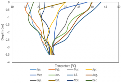
The aim of this experimental study is to arrive at an optimization design of a ground heat exchanger that works with a small area of land when there is no space available to install this system. as well as be compatible with the physical conditions of the region. Additional of that the purpose of our research is to provide information for practitioners to enable geothermal heat exchanger to be properly applied, and their environmental and economic potential to be realised. Specifically it aims to provide understanding of the technology, its design and its applications, information on maintenance, training and resources information on real performance with case studies. This design can be accomplished by studying experimentally the main parameters that affect the performance of the ground heat exchanger. According to the previous literature, these main parameters are: the buried depth (where the pipes are buried in the soil), the effect of the flow rate of fluid that is pumped into the system, the type of soil in which the pipes are buried, as well as the effect of the type of pipe material on the performance of the ground heat exchanger. In Figure 1 that the type of soil has a profound effect on the temperature calculation, depending on the depth in which the underground heat exchanger tubes are buried throughout the months of the year during one year.
Figure 1. The annual thermal gradient of soil at multiple depths
There are more than a few parameters that affect the performance of a ground heat exchanger, such as the material of pipe that is used in the design of the ground heat exchanger, temperature, and the mass flow rate of inlet water that interring the system. In this study, two different types of materials of pipes were used in the design of a ground heat exchanger, so the results show that the performance of the ground heat exchanger with PEX pipe is greater than the MLCP PIPE ground heat exchanger at all times of day. The increase in the temperature of the water interring from 30℃ to 50℃ led to an increase in the performance coefficient of GHEX. The maximum cop at 3 LPM at 7:30 am was 12.897 and it became 10.2559 at 3 LPM at 7:30 am. While the COP is decreased at 4LPM, the maximum value of it is 5.99 at 8:30 am. This behavior of the thermal performance coefficient of a ground heat exchanger is because it is equal to the ratio between the heat removed from the system and the amount of electrical power, and since the amount of heat is affected by the rate of water flow, these results can be attributed to fluctuations in heat.
The unsteady state radial heat conduction equation with negligible heat flux has been solved in order to calculate the thermal performance and the length of pipes that must be employed in the construction of the ground heat exchanger as shown in Eq. (1) [13].
$\frac{\partial^2 T}{\partial r^2}+\frac{1}{r} \frac{\partial T}{\partial r}=\frac{1}{a} \frac{\partial T}{\partial t}$ (1)
Boundary conditions:
)B.C.1(: $-2 \pi r_b k \frac{\partial T}{\partial r}=q^{\prime}$ at $r \rightarrow 0$
)B.C.2) : $T-T_0 \rightarrow 0$ where $r \rightarrow \infty$
(B.C.3): $T-T_0=0$ at $t=0$
$\left\{\begin{array}{l}-2 \pi r_b k \frac{\partial T}{\partial r}=q^{\prime} \text { at } r \rightarrow 0 \quad B.C.1\\ T-T 0 \rightarrow 0 \text { where } r \rightarrow \infty \quad B.C.2\\ T-T_0 \rightarrow 0 \text { at } t=0\quad B.C.3\end{array}\right.$ (2)
By applying B.C.1 and B.C.2 and B.C.3 in Eq. (1) the following equation can be obtained.
$T_{(r, t)}-T_0=\frac{q^{\prime}}{4 \pi k}$ (3)
2.1 Thermal resistance
Thermal resistance is determined by the pipe material and the circulating fluid in pipes. Currently, the thermal resistance has been calculated to analyse the inlet and outlet temperatures and effective thermal conductivity of circulating fluid according to the type of material that is made from the pipe. The pipe control element, which shows the thermal resistance, has been indicated in Figure 2.
Figure 2. Control element of pipe
Thermal resistances of the system which noticed in Figure 2 can be express as following [14]:
$R_{\text {conv }}=\frac{1}{\pi D_i h_w}, R_{p i p}=\frac{\ln \left(\frac{D_o}{D_i}\right)}{2 \pi k_{p i p}}, R_{\text {soil }} \frac{1}{S k_{\text {soil }}}$ (4)
Hence, the total thermal resistance can be written as follows [13]:
$R_{\text {total }}=R_{\text {conv }}+R_{\text {pip }}+R_{\text {soil }}$ (5)
where, S is the shape factor of conduction of the pipe which determined by the following formula [15]:
$S=\frac{2 \pi}{\ln \left[\left(\frac{2 d}{D_o}\right)+\sqrt{\left(\frac{2 d}{D_o}\right)^2-1}\right]}$ (6)
In order to calculate the $R_{\text {conv }}$ the heat transfer coefficient $h_w$ must be calculated using the following empirical formula [16]:
$N u=\frac{h_w D_i}{k}=0.023\left(\frac{\rho V D_i}{\mu}\right)^{0.8}(P r)^{0.3}$ (7)
Differential heat transfer is expressed as [16]:
$d q=-m_w^o c_w d T_w=\frac{T_w-T_{\text {soil }}}{R_{\text {total }}} d x$ (8)
Also,
$\theta_w=T_w-T_{\text {soil }}$ and $X=\frac{d x}{m_w^o c_w R_{\text {total }}}$ (9)
Then the Eq. (8) can be written as:
$\frac{d \theta_w}{d X}=\theta_w$ (10)
The boundary conditions are:
At $x=0 \rightarrow X=0$ then, $\theta_w=T_w-T_{\text {win }}=\theta_{\text {win }}$ (11)
At $x=L \rightarrow X=\frac{L}{m_w^o c_w R_{\text {total }}}, \theta_w=\theta_{\text {wout }}=T_{\text {wout }}-T_w$ (12)
By solving the above equations:
$\frac{\theta_w}{\theta_{\text {win }}}=e^{\left(\frac{-x}{m_w^o c_w R_{\text {total }}}\right)}$ (13)
$L=\left(m_w^o c_w R_{\text {total }}\right) \ln \left(\frac{\theta_{\text {wout }}}{\theta_{\text {win }}}\right)$ (14)
Hence, Table 1 shows the parameters that were evaluated to find the length of pipes used in the design of GHX:
Table 1. Main parameters to evaluate the length of pipes
|
$\dot{m}$ (kg/sec) |
0.041933 |
|
Di (m) |
0.012 |
|
Do (m) |
0.016 |
|
u (m/sec) |
0.7461 |
|
Re |
6330.21779 |
|
Q (w) |
1752 |
|
Pr |
4.721 |
|
Nu |
40.277 |
|
hw (w/m.K) |
2092.447 |
|
Kpipe (W/m.k) |
0.035 |
|
$R_{\text {total }}$ (K/w) |
0.60939 |
|
L (m) |
117.293 |
According to the above parameters, the length of the pipe used in operation design is equal to (100 m) not (117.293 m), because that maintains efficient performance design and low cost, so that probably the rate of heat transfer Q becomes less than 1752 W for one layer [13].
2.2 Coefficient of performance COP
The main way to figure out how well GHX was designed is by looking at the coefficient of performance, which is shown in Eqns. (15) and (16) [17] for heating and cooling the space, respectively.
COPHP $_{\text {space heating }}=\frac{\text { Heat provided to heated space }}{\text { Electricity consumption }}$ (15)
COPHP $_{\text {space cooling }}=\frac{\text { Heat removed from cooled space }}{\text { Electricity consumption }}$ (16)
Electric power can be calculated from the following term [17]:
Power $=I V$ (17)
In order to be a system with high efficiency, the COP must be high. In addition, the COP is affected by the temperature difference between high and low-temperature media. Therefore, COPHP decreases at larger temperature differences. So, in an ideal heat pump, the COP depends on high and low temperatures [17].
COP $_{\text {cooling }}=\frac{1}{1-\frac{T \text { cooling coil }}{T f}}$ (18)
$C O P_{\text {heating }}=\frac{1}{1-\frac{T f}{T_{\text {heating coil }}}}$ (19)
The main important thing observed generally in the study of any type of GHX, which is known by its Energy Efficiency Ratio (EER) [17],
$E E R=E_{\text {tot }} / E_{\text {consumed }}$ (20)
The values of EER for ground source heat pumps are generally in the range of 15 to 25.
Then, the equation for calculating the heat transferred from the working fluid to the soil via the ground heat exchanger as shown below [17]:
$Q=\dot{m} C p\left(T_{\text {in }}-T_{\text {out }}\right)$ (21)
2.3 Distance between pipes centers
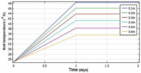
Figure 3. Soil temperature vs time of operation
The horizontal distance between the pipes is restricted by the soil temperature (Tsoil). So, the following chart, which is obtained, shows the relationship between the temperature of soil vs time of operation of GHEX at different spaces between the pipes.
The space between pipes can be estimated from Figure 3, where it can be seen from this chart that the temperature of the soil is gradually rising for the nearby pipes during the first day, after that it becomes stable at a constant temperature on other days. Hence, it can be concluded that this space (H) has a range between (0.4 – 0.6). According to the calculations in this paper, the value of (H) is equal to 0.4 m.
In this investigation, two experimental systems have been built with the same arrangements, where the difference between the two experimental tests is based on the type of material of the pipe of GHE and the depth of burial in the soil. Figure 4 explains the schematic arrangement of the experimental system for both of the two experiments. The first experimental set-up of GHE consists of a PEX tube with thermal conductivity (K = 0.035 W/m.℃), buried at 2 m depth, with an external and internal diameter of 20 mm and 16 mm, respectively. The distance between tubes is 0.4 m to decrease the interference between them [14, 15]. The second experimental test system is constructed from MLCP tube with thermal conductivity (K = 0.04 W/m. ℃), 16 mm as external diameter, and 12 mm as internal diameter, buried at two values of depth in the soil, at 2.5 and 3m.
Figure 4. Experimental test of the ground heat exchanger
Figure 4 shows the instruments that are used to measure the mass flow rate and temperature of the water, which has been explained as follows: The flow rate is controlled by a unit consisting of a valve and an accurate digital flowmeter to control the direction of water flow. A datalogger has been used in order to measure the water inlet and outlet temperatures. This instrument has four temperature sensors and was connected to measure the inlet and outlet temperature of the water, as well as to measure the temperature of the soil and ambient temperature. The critical factor that can affect the energy transfer from water to soil or vice versa is the thermal conductivity of soil, which is measured by the soil lab. Thermal conductivity is measured after many steps and is found to be equal to (1.7-2.1) w/m.0k. There are many assumptions that are taken into consideration. 30-50℃ is the beginning temperature of the working fluid. The volumetric flow rate of the working fluid (2, 3, and 4 LPM) was determined while measuring the thermal gradient of the soil in increments of 0.5 m from the surface to a depth of 3 m during the course of the year.
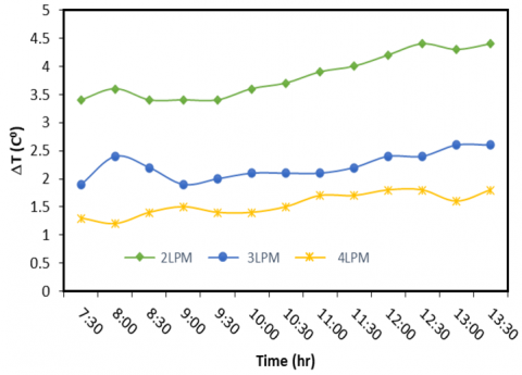
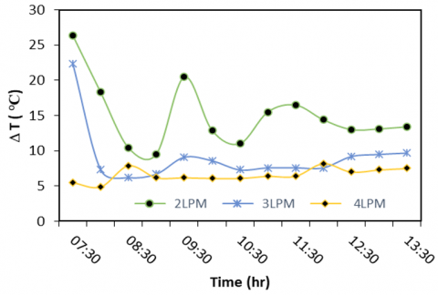
4.1 Temperature change at different flow rate
Figure 5 shows the temperature difference of water inlet to the ground heat exchanger at different values of flow rate. The inlet temperature is equal to (30℃) and the burial depth is 2 m. The results of the experimental data on the rate of temperature change were recorded from 7:30 am to 1:30 pm. Accordingly, the temperature difference gradually increases with time at all flow rates. Also, this figure has been shown to show that there is a decrease in temperature change with increasing flow rate. This is due to the fact that an increase in the fluid flow rate leads to an increase in the fluid velocity rate, and since an increase in the fluid velocity leads to an increase in the external temperature. So, according to Eq. (19), the temperature change is inversely proportional to the fluid flow rate.
Figure 5. The comparison of temperature change vs time at different flow rates at Tin =30℃
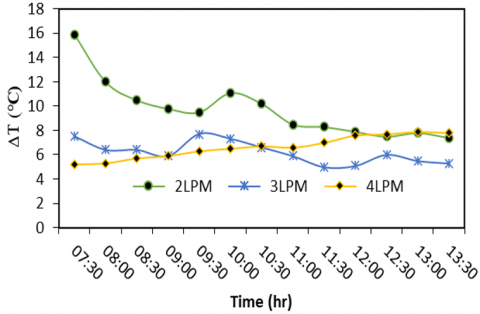
Figure 6. Temperature change vs time at a different flow rate, Tin =40℃
When the water entry temperature increases to 40℃, the temperature change continues to decrease with time, as shown in Figure 6. As for the effect of the rate of water flow on the change in the temperature of the outgoing water, when increasing the flow rate from 2 LPM to 3 LPM, the rate of change begins to decrease, and this is the same explanation in Figure 7. While at 4 LPM, the changing temperature of outlet water increases with time. This is because the outlet water temperature fluctuates. By increasing the inlet temperature of water to 50℃, the change of temperature of outlet water with time becomes unstable for all flow rates at a range of time (7.30 am-11.30 pm). After this period of time, the change in temperature becomes stable where it is close to (26.4℃, 22.4℃, 5.5℃) for (2, 3, 4 LPM) respectively.
Figure 7. Temperature change vs time at a different flow rate, Tin = 50℃
4.2 Performance of ground heat exchanger
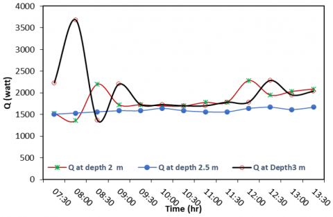
An experimental set-up was constructed for the climatic conditions of Hilla, south of Baghdad in Iraq. The purpose of this study is to analyse the effect of buried depths of the ground heat exchanger. So, three experiments have been done, the first experimental buried at 2 m and the others buried at 2.5 and 3 m, respectively. In order to study the performance of GHX, the effect of buried depth on heat removed from the space must be studied. Hence, Figure 8 has be shown to have this effect at a fixed flow rate equal to 4 LPM and a fixed inlet temperature of water equal to approximately 50℃. The first experiment has shown that the maximum heat removed is equal to 2200.942 watts at 8.30 am when buried at a depth of 2 m. The second experiment shows that peak heat removed reached 3679.474 watts at 8 am where the buried depth was 3 m. Figure 8 shows that the removed heat is approximately stable at all times.
Figure 8. Heat removed vs time at different burial depths
On the other hand, the effect of changing the flow rates on heat removed from the ground heat transfer system is studied as shown in Figure 9. The buried depth of Pex pipes is 2 m. The inlet water temperature (50℃) is chosen as a case study to analyse this effect. This figure shows that the heat removed has reached its maximum at 3 LPM. Note that the relationship between the amount of heat removed with time is in a state of fluctuation.
Figure 9. Heat removed vs time at different flow rates
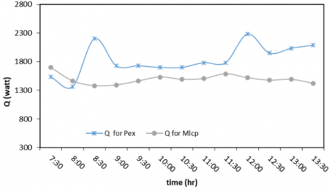
In this paper, the amount of heat removed from a ground heat exchanger with pipes made of pex material was compared with another with pipes made of a MLCp material, and they were buried at a depth of 2 m. This comparison was performed at a temperature of 50℃ and at a flow rate of 4 LPM, as shown in Figure 10. Hence, this study showed that the amount of heat removed in pipes made of a pex material is higher than that made of MLCP material. This is due to their advantages where it can conserve energy better than others. Water also moves more smoothly through PEX. Another advantage of PEX is that it doesn't corrode like copper. This is important if the water is slightly acidic. Besides, and from the practical point of view, pipes made of MLCP material are considered easy to install.
Figure 10. Heat removed vs time at different materials of pipes
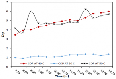
One of the most important quantities to be studied in this research is the thermal performance coefficient and the most important factors affecting it. The effect of the temperature of the water entering the system of the ground heat exchanger at a constant flow rate of 4 LPM and the burial depth of the Pex pipes is 2 m. This study was carried out at three temperature values, which are 30, 40, and 50℃, respectively, as noted in Figure 11. This figure shows that, in general, increasing the inlet water temperature leads to an increase in the thermal performance coefficient with a constant water flow rate. Also, it notes that the thermal performance coefficient is almost constant with time at 30℃, where it reached its highest value of 1.374 at 10:30 am. As for its value at a temperature of 40℃, it starts to increase from 8:30 AM until 1:30 PM, where it reaches 5.98284. In the case where the temperature of the inlet water is 50℃, the thermal performance coefficient reached its maximum value of 6.2197 at 12 PM, which is the highest value of the thermal performance rate. In this case, that means the system of the ground heat exchanger is good at working. The COP is almost constant from 9:00 a.m. to 11:30 a.m.
Figure 11. Coefficient of performance vs time at different inlet water temperature, water flow rate (4 LPM), buried depth 2m
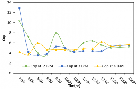
The effect of the inlet water flow rate on the COP has been shown in Figure 12. The case chosen for this effect has an inlet temperature equal to 50℃ and a buried depth of 2 m as the buried depth of Pex pipes.
Figure 12. Effect of flow Rate on coefficient of performance of ground heat exchanger
Figure 13. Effect of materials of pipe of ground heat exchanger on its performance
The maximum cop at 3 LPM at 7:30 am was 12.897 and it became 10.2559 at 3 LPM at 7:30 am. While the COP is decreased at 4LPM, the maximum value of it is 5.99 at 8:30 am. This behaviour of the thermal performance coefficient of a ground heat exchanger is due to the fact that it is equal to the ratio between the heat removed from the system to the amount of electrical power, and since the amount of heat is affected by the rate of water flow, as noted in Figure 9, where there was a fluctuation in the amount of heat. The effect of the material of pipes used in the design of the ground heat exchanger on thermal performance has been studied in Figure 13. The case that was used for comparison is 2m as buried depth and 4 LPM as inlet water flow rate. The inlet water temperature is 50℃. When Pex pipes are used in these conditions, their COP can be higher than the COP of MLCP pipes. It can be seen from Figure 13 that the cop of MLCP is almost constant with time, while it increases with time for Pex.
Through the current study, which looked at the performance and design of a ground heat exchanger that would work in Iraq, specifically in the Babil Governorate, we can draw some important conclusions:
The future research direction could involve the study of a new design of ground heat exchanger that consists of a two-layer heat exchanger that can be operated alternately to avoid the thermal accumulation in the soil around the tubes that occurs over time. Also, an underground heat exchanger can be designed as an open system and allow a comparison in performance between the system in the present work and the next study. The type of fluid can have an effect on the performance. The use of Nano fluid in enhancing heat transfer could be a good study. Using a system that is used to draw the heat from the soil, warm the fluid circulating inside the pipes, and test their performance. All of the above recommendations can be good studies for future research.
|
Cpmean |
Mean heat capacity of working fluid, kJ/kg. °C |
|
R |
Gas constant, J/mol. k |
|
di |
Pipe inside diameter, m |
|
do |
Pipe outside diameter, m |
|
k |
Thermal conductivity of fluid inside the pipe W/m.℃ |
|
kt |
Thermal conductivity of pipe, W/m. ℃ |
|
Q |
Volumetric flow rate, Lpm |
|
T |
Temperature, °C |
|
TT |
Temperature of fluid in the tank, ℃ |
|
Tw |
Temperature of water inside the pipe, ℃ |
|
Ts |
Temperature of soil outside the pipe, ℃ |
|
Tg |
Temperature of gasoil inside the pipe, ℃ |
|
ρ |
Density of fluid in the pipe, kg/m3 |
|
u |
Velocity of fluid inside the pipe, m/s |
|
L |
Length of the pipe, m |
|
U |
Overall heat transfer coefficient, W/m2. K |
|
m |
Mass flow rate of fluid, kg/s |
|
α |
Thermal diffusivity, m2/s |
|
cs |
Specific heat of soil, kJ/kg. K |
|
ρs |
Density of soil, kg/m3 |
|
ks |
Thermal conductivity of soil, W/m. K |
|
cw |
Specific heat of water, kJ/kg. K |
|
w |
Moisture water content of soil |
|
q |
Total rate of heat transfer, Watt |
|
$\Delta \mathrm{T}$ |
Overall temperature difference of fluid, ℃ |
|
Re |
Reynold number |
|
Pr |
Prandtle number |
|
hi |
Pipe inside heat transfer coefficient, w/m. k |
|
ho |
Pipe outside heat transfer coefficient, w/m. k |
|
Rt |
Thermal resistance of pipe, k/W |
|
Ri |
Pipe inside thermal resistance, k/W |
|
RO |
Pipe outside thermal resistance, k/W |
|
µ |
Dynamic viscosity, kg/m.s |
|
Nud |
Nusselt number |
[1] Ozgener, L., Ozgener, O. (2010). An experimental study of the exergetic performance of an underground air tunnel system for greenhouse cooling. Renewable Energy, 35(12): 2804-2811. https://doi.org/10.1016/j.renene.2010.04.038
[2] Fujii, H., Okubo, H., Cho, N., Ohyama, K. (2010). Field tests of horizontal ground heat exchangers. In 4th World Geothermal Congress. http://www.lovegeothermal.org/pdf/IGAstandard/WGC/2010/2904.pdf.
[3] Chen, J., Xia, L., Li, B., Mmereki, D. (2015). Simulation and experimental analysis of optimal buried depth of the vertical U-tube ground heat exchanger for a ground-coupled heat pump system. Renewable Energy, 73: 46-54. https://doi.org/10.1016/j.renene.2014.06.007
[4] Naili, N., Hazami, M., Attar, I., Farhat, A. (2013). In-field performance analysis of ground source cooling system with horizontal ground heat exchanger in Tunisia. Energy, 61: 319-331. https://doi.org/10.1016/j.energy.2013.08.054
[5] Naili, N., Hazami, M., Attar, I., Farhat, A. (2016). Assessment of surface geothermal energy for air conditioning in northern Tunisia: Direct test and deployment of ground source heat pump system. Energy and Buildings, 111: 207-217. https://doi.org/10.1016/j.enbuild.2015.11.024
[6] Kumar, R., Jain, P.K., Dwivedi, P. (2016). Prediction of compression index (Cc) of fine grained remolded soils from basic soil properties. International Journal of Applied Engineering Research, 11(1): 592-598.
[7] Belloufi, Y., Brima, A., Zerouali, S., Atmani, R., Aissaoui, F., Rouag, A., Moummi, N. (2017). Numerical and experimental investigation on the transient behavior of an earth air heat exchanger in continuous operation mode. International Journal of Heat and Technology, 35(2): 279-288. https://doi.org/10.18280/ijht.350208
[8] Park, Y., Song, J.Y., Lee, G.C., Kim, K.J., Mok, J.K., Park, Y.C. (2017). Performance analysis of ground heat exchanger in combined well and open-closed loops geothermal (CWG) system. Journal of Soil and Groundwater Environment, 22(5): 23-29. https://doi.org/10.7857/JSGE.2017.22.5.023
[9] Hassanzadeh, R., Darvishyadegari, M., Arman, S. (2018). A new idea for improving the horizontal straight ground source heat exchangers performance. Sustainable Energy Technologies and Assessments, 25: 138-145. https://doi.org/10.1016/j.seta.2017.12.006
[10] Baglivo, C., Bonuso, S., Congedo, P.M. (2018). Performance analysis of air cooled heat pump coupled with horizontal air ground heat exchanger in the mediterranean climate. Energies, 11(10): 2704. https://doi.org/10.3390/en11102704
[11] Durmaz, U., Yalcinkaya, O. (2019). Experimental investigation on the ground heat exchanger with air fluid. International Journal of Environmental Science and Technology, 16(9): 5213-5218. https://doi.org/10.1007/s13762-019-02205-w
[12] Ahmadi, S., Irandoost Shahrestani, M., Sayadian, S., Maerefat, M., Haghighi Poshtiri, A. (2021). Performance analysis of an integrated cooling system consisted of earth-to-air heat exchanger (EAHE) and water spray channel. Journal of Thermal Analysis and Calorimetry, 143(1): 473-483. https://doi.org/10.1007/s10973-020-10357-y
[13] Said, S.A.M., Habib, M.A., Mokheimer, E.M.A., Al-Shayea, N., Sharqawi, M., Arabia, D.S. (2009). Horizontal ground heat exchanger design for ground-coupled heat pumps. In International Conference and Exhibition of Ecologic Vehicles and Renewable Energies.
[14] Sivasakthivel, T., Philippe, M., Murugesan, K., Verma, V., Hu, P. (2017). Experimental thermal performance analysis of ground heat exchangers for space heating and cooling applications. Renewable Energy, 113: 1168-1181. https://doi.org/10.1016/j.renene.2017.06.098
[15] Patel, R.D., Ramana, P.V. (2016). Experimental performance of buried tube heat exchanger validated by simulation performance in heating climate condition. Indian Journal of Science and Technology, 9(33): 1-6. https://doi.org/10.17485/ijst/2016/v9i33/98788
[16] Incropera, F.P., Dewitt, D.P. (2002). Fundamentals of Heat and Mass Transfer. http://www.mid-contracting.com/sites/default/files/webform/careers_webform/_sid_/pdf.
[17] Glassley, W.E. (2014). Geothermal Energy: Renewable Energy and the Environment. CRC Press. https://books.google.com.my/books?hl=en&lr=&id=hPCsBAAAQBAJ&oi=fnd&pg=PP1&dq=%5B17%5D%09Glassley,+W.+E.+(2014).