Louis Magthelin Therase* | Thangappan Jayanthy
© 2021 IIETA. This article is published by IIETA and is licensed under the CC BY 4.0 license (http://creativecommons.org/licenses/by/4.0/).
OPEN ACCESS
Metamaterials have gained a lot of interest in modern wireless devices due to their electromagnetic characteristics and it is employed to improve antenna parameters such as bandwidth, gain and efficiency. The study presents a novel strategy of single split non-uniform width Complementary Split Ring Resonator (CSRR) equipped Circular ring Microstrip Antenna (CRMA). The radiating element dimensions are seen to be 20 mm x 20 mm at the initial working frequency wherein the CSRR is incorporated on the ground plane of CRMA. The single split non-uniform width metamaterial (CSRR) structure displays -10 dB impedance bandwidth at 11.1 and 13.56 GHz which is beneficial for applications pertaining to X and Ku band. The total bandwidth of the said metamaterial antenna is 4 GHz (10.73-14.75). Optimization is undertaken with the help of commercially assessable simulation software tool Ansys HFSS 2019 version and practically measured using network analyzer. It is quite obvious from the experimentation that the results calculated get along well with the assumed outcomes.
annular ring printed antenna, bandwidth, complementary split ring resonator, dual band, efficiency, non-uniform width, single split
There seems to be a rapid increase in the areas of modern wireless devices and RF microwave systems with the need to assimilate extra communication criteria thereby providing an eminent facility of service. Microstrip patch antenna which is also called as printed antenna, made-up using microstrip methods, is attaining much admiration with its compact quality, low profile and minimal weight along with its essential potentials that are also extensively recounted in literature [1, 2].
With an aim to lower the restrictions of the patch antenna, many methods are proposed with the help of artificial structures called metamaterials. In order to improve the gain in antenna, efficiency, bandwidth and accomplish miniaturization, metamaterial defects are utilized in printed antennas applications. The distinctive structures of the Split-Ring Resonator (SRR) whose electrical characteristics depends on the axial magnetic field and its dual the Complementary Split Ring Resonator (CSRR) which responds to axial electric field are the major constituents of metamaterial that are previously discoursed in literature [3]. Further discussion and investigation are taken up for parallel equivalent circuit models of SRR and its dual CSRR that comprises corresponding LC circuit [4]. Pendry’s CSRR, a complement of split ring resonator (SRR) has previously gained substantial recognition in planar circuits owing to its double negative properties [5-8].
The main aim of the proposed work is to further enhance the bandwidth in a standard CRMA by altering the CSRR edifice on the ground plane. In this configuration, the antenna exhibited resonant frequencies at 11.16 GHz and 13.56 GHz with simulated S11 parameters of -45.56 dB and -25.49 dB respectively. The simulated impedance bandwidth (-10 dB) ranges from 10.73 to 14.75 GHz, with a 4 GHz (32%) bandwidth increase covering a variety of X and Ku band applications. This single loop non-uniform width metamaterial defected ground structure loaded CRMA produces improved impedance match, enhanced gain, efficiency and wider bandwidth. The study analyses the impact of single split CSRR on the standard inset feed CRMA and also examines with respect to the various antenna parameters.
The study taken here has been arranged as below: Section 2 summarizes the literature review related to CSRR antenna design. Section 3 takes care of the geometrical shape of CRMA and non-uniform width single split single loop CSRR unit cell together with its images and design features. The outcomes of improved CSRR single loop antenna designs are provided and tested through comparison are given in section 4. In the last section (Sec 5), the conclusion of the entire study is provided.
In this section few works related to CSRR antenna design mentioned in the literature have been discussed. Triple band planar antenna with array of CSRR engaged on the ground plane for C-band, medical BAN and X-band applications like satellite radio communication, Radar applications and satellite communications has been reported [9, 10]. A six band multi-split metamaterial antenna with SRR is established for several wireless devices [11]. A compact tri-band patch antenna using CSRR is created to bring in a novel arrangement for different wireless standards [12]. Multiband metamaterial antenna utilizing triangular split ring resonator is given by Mahendran et al. [13] for satellite applications. A compact multiband triangular CSRR based compact metamaterial antenna using trapezoidal patch is presented by Rajkumarand Kommuri [14] which covers WLAN, X-band downlink and ITU bands.
The outline of the upper view of the patch and the lower view of single loop CSRR of the proposed antenna are given in Figure 1.
Figure 1. Layout of proposed single split non-uniform CSRR structure (a) Upper view of patch layer (b) Lower view of single loop CSRR
Table 1. Sizes of the proposed antenna
|
Description |
Size (mm) |
|
Inner ring radius (R1) |
4 |
|
Outer ring radius (R2) |
8 |
|
Substrate length |
20 |
|
Substrate Width |
20 |
|
Substrate height (h) |
1.6 |
|
Inset feed line length (Lf) |
7 |
|
Inset feed line width (Wf) |
2 |
|
Length of the ground |
20 |
|
Width of the ground |
20 |
The inner radius R1 and outer radius R2 of the annular ring patch fed with microstrip line are 4 and 8 mm respectively. The fiscally obtainable dielectric Flame Retardant-4 having relative permittivity (εr) of 4.4 was chosen and the design is printed on 1.6 mm thickness (h) substrate. The radiating layer is excited by using inset feed technique having dimension of thickness (Wf) and length (Lf) of 2 and 7mm respectively to achieve perfect impedance matching between the annular ring patch and the microstrip line.
With the help of the equation below, the annular ring patch radius (R2) can be calculated for a given center frequency fr in GHz and relative substrate dielectric constant εr (F/m) [15]
$f_{r}=\frac{c}{\pi R_{2}} \sqrt{\frac{1+\varepsilon_{r}}{2 \varepsilon_{r}}}$ (1)
With the equation given below, the requisite minimal width (Wg) of the microstrip antenna ground plane can be attained [16].
$W_{g}=6 h+\frac{\pi}{2} R_{2}$ (2)
In the proposed design, single loop single split CSRR metamaterial structure is created on the ground plane by utilizing copper as a base material.
With the help of (1-2), the outer radius (R2) of the radiating ring structure and the minimal breadth of the antenna ground plane are obtained. The proposed antenna’s optimal values to attain better outcomes are given in Table 1.
The presented non-uniform width single loop single split CSRR antenna has been created by photolithographic procedure with the help of commercially obtainable FR4 substrate material as seen in Figure 2. The parameters such as return loss, VSWR and impedance of the given antenna are measured with the Anritsu Vector Network Analyzer.
Figure 2. Photographic view of the proposed CSRR antenna and the Measurement set-up
Figure 3 shows the produced and measured return loss characteristics of standard CRMA with whole ground plane configuration and CRMA loaded with single loop CSRR.
The obtained return loss value is-23.7 dB and 14.3dB for a standard CRMA resonating at 11.56 and 14.16 MHz respectively.
The -10 dB impedance bandwidth is determined with respect to lower cut-off (f1), upper cut-off (f2) and for center (fc) frequencies respectively using (3) shown below:
$\% \text { Bandwidth }=\left[\frac{f_{2}-f_{1}}{f_{c}}\right] \times 100$ (3)
The obtained−10 dB bandwidth is 560 MHz (11.35-11.91) and 1 MHz (13.71-14.75) with the overall bandwidth of 7.3%.
CRMA loaded with single loop non-uniform width CSRR configuration exhibited resonance frequencies at 11.16 and 13.56 GHz with obtained S11 parameter of -45.56 dB and −25.49 dB respectively. The simulated impedance bandwidth (−10 dB) was from 10.73 to 14.75 GHz which covers the various applications of X and Ku bands with the increased bandwidth of 4 GHz (32%). It is observed that the antenna resonating points are shifted towards left with reduction in electrical size and further improvement in return loss indicates that better impedance matching is achieved when the antenna is loaded with non-uniform width CSRR.
(a) Simulated
(b) Measured
Figure 3. S11 of proposed CSRR structure
(a)
(b)
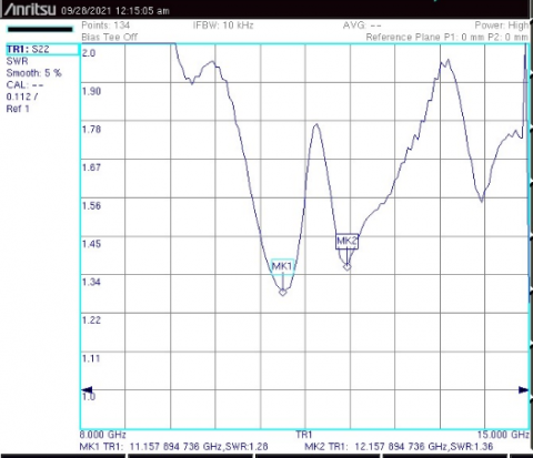
Figure 4. Simulated and measured VSWR
The measured dual band frequencies are 11.15 and 12.12 GHz with return loss of -18.12 dB and -16.24 dB respectively.
The derived and investigational Voltage Standing Wave Ratio (VSWR) are displayed in Figure 4. The VSWR values of 1.01 and 1.1 at the center frequency of 11.16 and 13.56 GHz are obtained. The produced results of VSWR specifies that the suggested edifice works effectively for the said dual frequencies with good matching.
The measured VSWR values are < 2 (1.28 and 1.36) for the dual frequencies 11.15 and 12.157 GHz respectively.
The simulated and measured impedance chart infers that at the operating frequency, the standardized impedances are much nearer to 50 $\Omega$ impedance of the inset feed microstrip line as shown in Figures 5 and 6.
Figure 5. Simulated impedance plot
Figure 6. Measured impedance plot
The produced and investigational outcomes of S11 and VSWR of the antenna defected with single split non-uniform width CSRR are displayed in Table 2 below:
Table 2. Simulated and measured results
|
|
Resonant frequency (GHz) |
Return Loss (dB) |
VSWR |
|
Simulated |
11.16 |
−45.56 |
1.01 |
|
13.56 |
−25.49 |
1.1 |
|
|
Measured |
11.15 |
−18.12 |
1.28 |
|
12.16 |
−16.24 |
1.36 |
Owing to SMA connector, forbearances in creation and faultiness in joining, there seems to occur discrepancy in the produced and investigational outcomes.
The 3D gain and directivity diagrams at 11.16 and 13.56 GHz are demonstrated in Figures 7 and 8. The produced maximal complete gain of X and Ku band antennas with non-uniform width CSRR are 3.4 dB and 4.6dB, while the directivity 6.2 dB and 6.9 dB is observed at the working frequency of 11.16 and 13.56 GHz respectively.
Figure 7. 3D gain plot at the resonating frequencies
Figure 8. Simulated directivity plot at the resonating frequencies
Figures 9 to 11 show the produced 2D radiation arrays of the CRMA loaded with single split single loop CSRR in the E and H planes conforming to 0°, 90°, and 180° respectively at 11.1 and 13.56 GHz.
The antenna effectiveness (η) is estimated with the help of the expression as follows:
$\eta=\frac{\text { Gain }}{\text { Directivity }}$ (4)
The calculated effectiveness of the metamaterial antenna at the operating band of frequency is 73.91% and 89.85% at 11.16 GHz and 13.56 GHz respectively.
It is seen from the produced outcomes that there are few benefits such as dual band, improved return loss, large bandwidth, improved gain and efficiency of the proposed single split non-uniform width CSRR loaded annular ring patch antenna.
Figure 9. Far field pattern at 0° for the proposed dual band design
Figure 10. Far field pattern at 90° for the proposed dual band design
Figure 11. Far field pattern at 180° for the proposed dual band design
A single loop non-uniform width CSRR is outlined, created and examined. The operational parameters like return loss magnitude, VSWR, gain and directivity are being simulated. The figured effectiveness of the antenna so designed was 73.91% at 11.16 GHz and 89.85% at 13.56 GHz that makes it apposite for wide band systems working in X and Ku-band. The designed antenna promises an advantage of large bandwidth as well as improved impedance matching so that a single antenna can cover multiple applications. This design introduces a novel approach to the design of small dual-band antennas. The fabricated dual band CSRR antenna’s performance was assessed and the experimental and simulated outcomes prove that both the results are in agreement with some discrepancies.
[1] Balanis. C.A. (2016). Antenna Theory: Analysis & Design. John Willey & Sons.
[2] Guha, D., Antar, Y.M.M. (Ed.) (2011). Microstrip and Printed Antennas, New Trends, Techniques and Applications. 1st edition. John Wiley & Sons.
[3] Caloz, C., Itoh, T. (2006). Electromagnetic Metamaterials: Transmission Line Theory and Microwave Applications. Wiley.
[4] Baena, J.D., Bonache, J., Martin, F., et al. (2005). Equivalent-circuit models for split-ring resonators and complementary split-ring resonators coupled to planar transmission lines. IEEE Trans Microwave Theory Tech., 53(4): 1451-1461. https://doi.org/10.1109/TMTT.2005.845211
[5] Ahmed, S., Chandra, M. (2017). Design of a dual linear polarization antenna using split ring resonators at X-band. Advances in Radio Science, 15: 259-267. https://doi.org/10.5194/ars-15-259-2017
[6] Smith, D.R., Willie Padila, J., Vier, D.C., Nemat-Nasser, S.C., Schultz, S. (2000). Composite medium with simultaneously negative permeability and permittivity. Physical Review Letters, 84(18): 4184-4187. https://doi.org/10.1103/PhysRevLett.84.4184
[7] Ricardo, M., Ferran, M., Mario, S. (2007). Metamaterials with Negative Parameters: Theory, Design, and Microwave Applications. Wiley. https://doi.org/10.1002/9780470191736
[8] Bhadra Choudhuri, S.R., Poddar, D.R., Ghatak R., Mishra. R.K. (2009). Modulating properties of a microstrip patch antenna using complementary split ring resonator. IEEE International Workshop on Antenna Technology. https://doi.org/10.1109/IWAT.2009.4906930
[9] Magthelin Therase, L., Jayanthy, T. (2021). Metamaterial integrated superstrate antenna for c, x, and ku bands applications. International Journal of Engineering Trends and Technology, 69(6): 38-42. https://doi.org/10.14445/22315381/IJETT-V69I6P206
[10] Prashant, R.T., Vani, R.M. (2014). Microstrip patch antenna with complementary split ring resonator for triple-band operation. International Journal of Engineering Trends and Technology, 18(5): 224-229. https://doi.org/10.14445/ 22315381/IJETT-V18P246
[11] Siddiky, A.M., Faruque, M.R.I., Islam, M.T., Abdullah, S. (2021). A multi-split based square split ring resonator for multiband satellite applications with high effective medium ratio. Results in Physics, 22: 103865. https://doi.org/10.1016/j.rinp.2021.103865
[12] Kumar Rajesh, N., Sathya, P.D., Rahim, S.K.A., Nor, M.Z.M., Alomainy, A., Eteng, A.A. (2021). Compact tri-band microstrip patch antenna using complementary split ring resonator structure. Applied Computational Electromagnetics Society Journal, 36(3): 346-353. https://doi.org/10.47037/2020.ACES.J.360314
[13] Mahendran, K., Gayathri, R., Sudarsan, H. (2021). Design of multi band triangular microstrip patch antenna with triangular split ring resonator for s band, c band and x band applications. Microprocessors and Microsystems, 80: 103400. https://doi.org/10.1016/j.micpro.2020.103400
[14] Rajkumar, R., Kommuri, U.K. (2018). A triangular complementary split ring resonator based compact metamaterial antenna for multiband operation. Wireless Personal Communications, 101(2): 1075-1089. https://doi.org/10.1007/s11277-018-5749-7
[15] Wong, K.L., Huang, C.C., Chen, W.S. (2002). Printed ring slot antenna for circular polarization. IEEE Trans. Antennas Propagation, 50(1): 75-77. https://doi.org/10.1109/8.992564
[16] Wong, K.L. (2002). Compact and Broadband Microstrip Antennas. John Wiley & Sons. https://doi.org/10.1002/0471221112