Shaktijeet Mahapatra | Mihir Narayan Mohanty*
© 2021 IIETA. This article is published by IIETA and is licensed under the CC BY 4.0 license (http://creativecommons.org/licenses/by/4.0/).
OPEN ACCESS
Body area network has facilitated monitoring, authentication and security through sensors or microstrip antenna with specified frequency. The purpose of this research work is to propose a simplified way to search for an optimal length of the inset for edge feeding using the Evolutionary Algorithm search by minimizing the reflection coefficient using ANSYS HFSS. The optimal inset length resulted in an antenna with better radiation efficiency and wider bandwidth. The antenna structure is 70x70x1.6 mm3, with a modified ground. The purpose of this antenna is communication in Ultra-wideband and works in 5.4, 8.1, and 9.8 GHz bands respectively. The resonant bandwidth measured are 1.02, 0.28, 0.12 GHz, respectively. Simultaneously the achievable gains are 3.18, 7.81, and 19.95 dB, respectively in free space. As the antenna is of wearable type, the front-to-back ratio evaluated for each band is 2.31, 7.01, and 13.91 respectively. The results of the fabricated antenna agree with the simulated results. The specific absorption rates at resonant frequencies were observed to be 0.3, 0.56 and 0.24 W/kg respectively when antenna is placed on a human tissue model. The antenna is useful for on-body communication at ISM band, and high data rate off-body communication in body area networks.
evolutionary algorithm, hexagonal microstrip antenna, inset-fed, low SAR, multi-band antenna, wearable antenna
Today’s scenario of technology wearable devices has covered almost every sphere. The devices that are put on the body are used for monitoring various vital biomedical parameters, and tracking the movement of the living subjects, for medical, military, security, and business uses [1, 2]. As the number of services offered by these devices increase, the need for antennas operating in specific frequencies of the services have increased. Here multi-band antennas play a major role. A single antenna services multiple frequencies efficiently utilizing the frequency spectrum and eliminates the need for multiple antennas for different frequencies, minimizing the risk of exposure to radiations.
In this paper, we propose a hexagonal antenna. It is fed through one its edges at an inset. The ground plane has been modified to include 16 equal rectangular slots placed equidistant from each other. Due to the hexagonal design, the antenna operates in three bands, with considerable gain and bandwidth. The design can be easily integrated with the printed circuit boards. For improvement of matching of the port to the antenna, the inset feed is used. The length of the inset is optimized through evolutionary algorithm. The algorithm uses Darwinian concept of evolution involving natural selection of fittest individuals from the population. The candidate solutions are selected based on their fitness criteria. The candidates with higher fitness coefficients are included in the search space (population), replacing less fit candidates. The solution with highest fitness coefficient is selected as the optimal solution. The antenna has been designed to operate in Ultra-wideband (UWB) range to allow for design of wearable devices in this range and exploit wider bandwidth and faster data rates. The bands have chosen to avoid interference from other narrow-band services.
The paper describes some related works on multiband antennas for wearable applications in section 2, antenna design using evolutionary algorithm in section 3, results and related discussion in section 4, and concludes with the conclusion section. The works that have been referred to are given in the references section.
The antennas for wearable purposes have been designed to operate in single and multiple frequency bands. However, the reduction of the SAR remains the biggest challenge.
For reducing SAR, an extra structure to reflect the back lobes away from the human body [3-6]. These reflector structures have been designed to present a negative relative magnetic permeability for incident radio waves.
There have been a few works that have been able to achieve low SAR without the use of extra reflecting structures and are compact in design. A printed omega-shaped monopole antenna with a modified ground is presented [7]. A monopole antenna with a defected ground structure, fabricated on a denim substrate is presented [8]. The antenna resonated in 2.12 GHz, 4.78 GHz, 5.75 GHz, and 6.11 GHz with return losses in the order of -51 dB. An inkjet-printed antenna is presented [9]. The antenna was designed on polyethyl terephthalate (PET) film. The antenna operated in 2.45 GHz and 5.8 GHz bands with a peak gain of 2.05 dBi and 3.63 dBi and had a SAR as high as 17 W/kg. A dual-band folded-shorted patch antenna fabricated on polydimethylsiloxane (PDMS) is presented [10] operates in 400 MHz and 2.4 GHz with gains of 1.4 dBi and 3.0 dBi, respectively. An ultra-wideband antenna is presented [11] features a hexagonal circular patch and asymmetric coplanar waveguide feed. The patch is loaded with a complementary split-ring resonator (CSRR) and four slits. The antenna resonates at 4.1 GHz, 7.2 GHz and 10.42 GHz. The antenna exhibited gains of -5.82 dB at 7.2 GHz and -8.66 dB at 10.42 GHz. A slotted hexagonal antenna operating at 2.4, 5.03, and 8.67 GHz with gains of 1.63, 1.38 and 2.95 dB is presented [12]. Authors worked with an ultrawide bandwidth was also able to limit the main lobe to a particular direction [13-15]. Different feed positions have been analyzed [16]. Optimization of antenna using Genetic Algorithm (GA) has been done [17, 18]. GA is employed for optimizing metamaterial design for enhancing gain of antenna for energy harvesting [19].
In comparison with previous works, the antenna proposed in this work can achieve high gain, wide bandwidth, and low SAR values at ISM band without the use of vias or any additional structures for reflection. The use of defected ground plane results in wide bandwidth and low SAR.
3.1 Design of the antenna
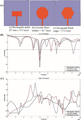
The proposed design of the antenna is hexagonal type. As compared to rectangular or circular patch, the hexagonal patch has an inherently multi-band nature, and use the available dielectric area more efficiently. The gains of the hexagonal patch are comparable to rectangular and circular patches. For a comparison, a rectangular, a circular, and a hexagonal patch is designed around 5 GHz on a 70×70×1.6 mm3 FR4-epoxy substrate with a feed width of 3 mm in Figure 1. There is no matching technique used. The ground plane is full. The S11 (dB) and the peak gain (dB) vs frequency are also shown.
Table 1. Summary of results
|
Parameters |
(Simulated/ Measured) |
(Simulated/ Measured) |
(Simulated/ Measured) |
|
Freq [GHz] |
5.4/ 5.85 |
8.1 / 8.02 |
9.8/ 10.2 |
|
S11 (< -10 dB) [dB] |
-37.95 / -30.19 |
-19.5 / -11.1 |
-28.58/ -15.62 |
|
Bandwidth [GHz] |
1.02 / 0.95 |
0.28 / 0.13 |
0.12/ 0.14 |
|
Peak Gain [in dB] |
3.18 |
7.81 |
19.95 |
|
Radiation Efficiency [%] |
57.23 |
52.39 |
85.09 |
|
Front-To-Back Ratio [dB] |
2.31 |
7.01 |
13.91 |
|
SAR [W/kg] |
0.3 |
0.56 |
0.24 |
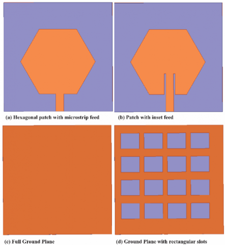
Step 1: A hexagonal copper patch with a side measuring 24.1 mm is created on a 70mm x 70mm x 1.6 mm substrate (Figure 2(a)).
Step 2: The feed of 5 mm is provided at one of the edges of the hexagon. A lumped port of 50Ω is created at the edge of the feed line (Figure 2(b)).
Step 3. A copper ground plane is created on the other side of the substrate (Figure 2(c)). 16 rectangular slots, each measuring 12mm x 10mm, are cut from the ground plane (Figure 2(d)).
Step 4: The distance of the inset is adjusted after running a Genetic Algorithm optimization to match the input impedance of the patch with the port. The dimensions that led to match are further given in Table 1.
Figure 1. (A) Different patch shapes, (B) Comparison of S11 vs frequency (C) Comparison of Gain vs frequency
Figure 2. Design steps
The hexagonal shape of the antenna can be approximated to its circumscribing circle of radius R. The sides of the hexagon subtend an angle of 60 deg (360/6) at the center. If the side of a hexagon is a, then,
$R=\frac{a / 2}{\cos \frac{2 \pi}{6}}=a$ (1)
Then the resonant frequency is given by Eq. (2) [20].
$f_{r}=\frac{8.794}{r_{e} \sqrt{\varepsilon_{r}}} G H z$ (2)
The effective radius re is calculated using Eq. (3) [11].
$r_{e}=R\left[1+\frac{2 h_{s}}{\pi R \varepsilon_{r}}\left\{\ln \left(\frac{R}{2 h_{s}}\right)+\left(1.4 \varepsilon_{r}+1.768\right)\right.\right. \left.\left.+\left(\frac{h_{s}}{R}\right)\left(0.267 \varepsilon_{r}+1.649\right)\right\}\right]^{-\frac{1}{2}}$ (3)
where, hs is the thickness of the substrate and εr is the dielectric constant of the substrate.
The effective side length of the hexagonal patch, ae, can be given as:
$\pi r_{e}^{2}=\frac{3 \sqrt{3}}{2} a_{e}^{2}$ (4)
The antenna is designed on a 70mm x 70mm x 1.6mm FR4-epoxy substrate. It has a relative electrical permittivity of 4.4 and a loss tangent of 0.02. The radiating patch of the proposed antenna has hexagonal shape. The length of each side is 24.1 mm. The ground plane has 16 rectangular slots, each measuring 12mm x 10mm. This modification helps to reduce the back lobe radiations to great extent, and hence the Specific Absorption Rate (SAR). A microstrip line of 5 mm width feeds the antenna at an inset, d from the edge. The feed point is slightly offset from the center. The distance of the inset, d, for best match with the 50Ω port have been determined through Evolutionary optimization.
3.2 Evolutionary optimization
The Genetic Algorithm optimization was run in Ansys HFSS between 1-10 GHz. The objective is to match the input impedance of the patch with that of the port for maximum power transfer, leading to better radiation efficiency, better gain and bandwidth while reducing the return loss. To find the best length of the feed for matching, we minimize the S11. This also determines the length of the inset, or how deep the inset slot should be etched. The input impedance of the circular patch any radial distance $\rho=\rho 0$ for dominant mode TM11 is given by [20]:
$Z_{i n}\left(\rho=\rho_{0}\right)=\frac{J_{1}^{2}\left(k \rho_{0}\right)}{\left(G_{t} \times J_{1}^{2}(k R)\right.}$ (5)
where, k is the wavenumber, J1(x) is the Bessel’s function of first kind of order 1, and Gt is the total conductance.
The total conductance, Gt is given by:
$G_{t}=G_{r a d}+G_{c}+G_{d}$ (6)
The conductance between the patch and the full ground plane, Grad is given by:
$G_{r a d}=\frac{\left(k_{0} R\right)^{2}}{480} \int_{0}^{\frac{\pi}{2}}\left[J_{02}^{\prime 2}+\cos ^{2} \theta J_{02}^{2}\right] \sin \theta d \theta$, (7)
The ohmic conductance, accounting for ohmic loss, Gc is given by:
$G_{c}=\frac{\epsilon_{m 0} \pi\left(\pi \mu_{0} f_{r}\right)^{-\frac{3}{2}}\left[(k R)^{2}-m^{2}\right]}{4 h_{s}^{2} \sqrt{\sigma}}$ (8)
The dielectric loss is accounted by Gd given by:
$G_{d}=\frac{\epsilon_{m 0} \tan \delta\left[(k R)^{2}-m^{2}\right]}{4 \mu_{0} h_{s} f_{r}}$ (9)
where, $\epsilon_{m 0}=2$ for $m=0, \epsilon_{m 0}=1$ for other m, and fr is the resonant frequency of the mn0 mode. The reflection coefficient is given by:
$\Gamma=\left(Z_{0}-Z_{L}\right) /\left(Z_{0}+Z_{L}\right)$ (10)
where, Z0 = 50Ω and ZL is given by Eq. (4). Hence the objective function is to keep the reflection coefficient below -20 dB and hence,
$\begin{aligned} S_{11}=-20 \log ((50&\left.-\frac{J_{1}^{2}(k(R-d))}{\left(G_{t} \times J_{1}^{2}(k R)\right.}\right) /(50+\left.\left.\frac{J_{1}^{2}(k(R-d))}{\left(G_{t} \times J_{1}^{2}(k R)\right.}\right)\right) \leq-20 \mathrm{~dB} \end{aligned}$ (11)
where, $\rho 0=R-d$. The constraints for this optimization are:
$d<\frac{a \sqrt{3}}{2}$
The fitness value for each individual is computed [18] as an average of S11 at all desired frequencies sampled at 10 MHz intervals between 0.01 GHz and 10 GHz.
Fitness Value $=\frac{1}{N} \sum_{i=0}^{N} C(f i)$ (12)
where, $C(f i)=\left\{\begin{array}{c}-20, \text { if } S 11(f i) \leq-20; \\ S 11(f i), \text { if } S 11(f i)>-20\end{array}\right.$.
Here, N is the number of sampling points, and C(fi) is the cost function and S11(fi) is the S11 or the return loss at ith frequency.
3.2.1 Optimization algorithm
Step 1: An initial set of 100 individuals is initialized randomly with different lengths of inset. For each individual, S11 is computed over the entire frequency range using equation (10) and fitness value for each individual is computed using (11). Based on their fitness values, individuals are then sorted.
Step 2: The fittest individuals and some random individuals are selected for reproduction of children through crossover and mutations, respectively. This ensures unbiased exploration of global optimum solutions. The fitness values of the children are also computed.
Step 3: All the individuals from previous generation and children are sorted according to their fitness values. The fittest individuals form the next generation of the population.
Steps 2 and 3 are repeated till fulfillment of the termination criteria.
The minimum and the maximum limit of the length of the inset slot was kept between 0.1 mm and 16 mm. The gap (q) between the feed-line and patch was kept at 1mm on both sides. The lowest cost obtained was for inset size of 13.366837201 mm or 13.37 mm. The antenna with finalized dimensions is shown in Figure 3.
Figure 3. Antenna after optimization (All dimensions are in mm)
4.1 Antenna in free space
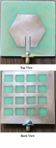
The fabricated antenna is shown in Figure 4. The S11 vs frequency plot shows the return loss at various frequencies. The lesser is the return loss, the better is the radiation efficiency of the antenna. The plot also gives information about the frequencies where antenna resonates. The frequencies where S11 is below -10 dB are considered as resonant frequencies. As can be observed from S11 vs frequency plot in Figure 5, the antenna resonates in three bands: 5.4 GHz, 8.1 GHz, and 9.8 GHz bands. However, after optimization, the bandwidth of the 5.4 GHz band increased to 1.02 GHz and covers the 5.8 GHz ISM band. The S11 at 9.8 GHz also reduced to -30 dB.
Figure 4. Fabricated antenna
Figure 5. S11 vs frequency
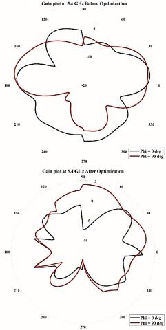
Figure 6. Gain plot at 5.4 GHz
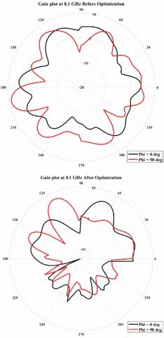
Figure 7. Gain plot at 8.1 G Hz
Table 2. Performance comparison of previous works
|
Reference |
Freq (GHz) |
Antenna Type/ Material/ Reflector |
Gain (dB) / Radiation efficiency (%) / SAR (W/Kg) |
|
[3] |
3.4/ 4.1 |
Rectangular MSA/RT Duroid 5880/AMC |
3.4GHz: 4.54/97.9/0.174; 4.1GHz: 4.71/98.6/0.207 |
|
[4] |
3.5/ 5.8 |
Monopole/Felt (Textile)/AMC |
3.5GHz: 6.71/79.1/3.28x10-6 5.8GHz: 7.82/66.1/9.37x10-7 |
|
[5] |
2.5/ 3.65 |
Circular Microstrip antenna/Substrate with dielectric constant 2.65/CRLH-based metasurface |
2.5 GHZ: 4.25/ /0.65; 3.65 GHz: 7.35/ /0.37 |
|
[6] |
5.8 |
Monopole/F4B/EBG |
9.1/85.6/0.212 |
|
[12] |
2.4/5.03/8.67 |
Hexagonal antenna with resctangular slots/ FR4 |
2.4 GHz: 1.63 5.03 GHz: 1.38 8.67 GHz: 2.95 |
|
This Work |
5.4/ 8.1/ 9.8 |
Hexagonal/FR4-epoxy/No extra reflector |
5.4GHz: 3.18/57.23/0.3; 8.1GHz: 7.81/52.39/0.56; 9.8GHz: 19.95/85.09/0.24 |
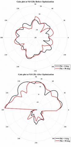
The gain plots at 5.4 GHz, 8.1 GHz, and 9.8 GHz before and after optimization are shown in Figures 6-8 respectively for E-plane (phi = 0 degrees) and H-plane (phi = 90 degrees). There are two major change in features that can be observed in the gain plots post optimization. The plots show that the back lobe levels are less than -1 dB and the gains of the major lobe have increased. The observations and measurements for different parameters like S11, bandwidth, gain, radiation efficiency and front-to-back ratio, are summarized in Table 1. The performance of the proposed design is compared with earlier works. This is given in Table 2. It is evidence of this simple design with better performance.
Figure 8. Gain plot at 9.8 GHz
4.2 Evaluation of antenna on human body
For evaluation of the performance of the antenna on the human body, the designed antenna was placed on a 10 x 10 x 0.15 cm3 2/3rd muscle model. The model consisted of skin, fat, and muscle layers. The layers were modelled as frequency-dependent lossy dielectrics. The dielectric constants (εr(ω)) and loss tangents of the layers were computed at 5.4 GHz, 8.1 GHz and 9.8 GHz using following relations [21]:
$\varepsilon_{r}(\omega)=\varepsilon_{\infty}+\sum_{m=1}^{4} \frac{\Delta \varepsilon_{m}}{1+\left(j \omega \tau_{m}\right)^{1-\alpha_{m}}}+\frac{\sigma_{i}}{j \omega \varepsilon_{0}}$ (13)
$\tan ^{-1} \delta=\frac{\operatorname{Im}(\varepsilon)}{\operatorname{Re}(\varepsilon)}$ (14)
where, $\varepsilon_{\infty}$ is the permittivity in terahertz region, $\varepsilon_{0}$ is the free space permittivity, $\sigma_{i}$ is the ionic conductivity, and $\varepsilon_{m}, \alpha_{m}, \tau_{m}$ are material parameters in the region of interest.
Using the values obtained, the specific absorption rate (SAR) is found out. SAR is a measure of the amount of electromagnetic radiation absorbed by living tissue. The amount of radiation absorbed is directly proportional to the amount of heating produced in the tissue sample. The major part of the radiation is directed away from the human body, thus lowering the SAR. This has been possible due to the modified ground plane structure. On the phantom, the antenna does not show a remarkable degradation in performance. It can be observed that the bandwidths are more than 150 MHz. With such a wide bandwidth, the antenna was able to resist the detuning effects due to proximity to the human body and can also resist the interference by different mobile devices.
The average SAR value was observed to be 0.3 W/kg when the antenna is placed on the phantom at 5.4 GHz. The average SAR at 8.1 GHz and 9.8 GHz were 0.56 W/kg and 0.24 W/kg respectively. These values are less than the cut-off value of 1.6 W/kg [22]. The result is very important because the antenna will be placed in proximity to the human body for body area network applications.
In this paper, a hexagon-shaped patch antenna with a modified ground plane and a GA-optimized microstrip inset feed has been proposed. For this problem, if the initial population is below 100, it under-fits and does not meet the objective. The population size beyond 100 found unstable fluctuations that may not satisfy the optimization condition. However, different algorithms may be tried for larger population size and is kept for future work. The antenna has a simple design, uses a popular substrate, and offers multi-band operation capability with workable gains, and good radiation efficiencies. The antenna operates in 3 bands 5.4 GHz, 8.1 GHz, and 9.8 GHz with an average bandwidth of more than 200 MHz and average radiation efficiency of around 60%. The antenna offers free-space gains of 3.18 dB, 7.81 dB, and 19.95 dB respectively. The SAR was observed to be below the threshold limits at all resonating frequencies. The antenna is suitable to be used for on- and off-body communications in body area networks in faster data transfer rates.
[1] Ashyap, A.Y.I., Dahlan, S.H.B., Zainal Abidin, Z., et al. (2020). An overview of electromagnetic band-gap integrated wearable antennas. IEEE Access, 8: 7641-7658. https://doi.org/10.1109/ACCESS.2020.2963997
[2] Mahapatra, S., Mohanty, M.N. (2021). A review on state-of-art techniques of antennas for body area networks. International Journal of Sensors, Wireless Communications and Control, 11(6): 604-618. https://doi.org/10.2174/2210327910999201228152543
[3] Hazarika, B., Basu, B., Kumar, J. (2018). A multi-layered dual-band on-body conformal integrated antenna for WBAN communication. AEU - International Journal of Electronics and Communications, 95: 226-235. https://doi.org/10.1016/j.aeue.2018.08.021
[4] El Atrash, M., Abdalla, M., Elhennawy, H. (2020). A fully-textile wideband AMC-backed antenna for wristband WiMAX and medical applications. International Journal of Microwave and Wireless Technologies, 13(6): 624-633. https://doi.org/10.1017/s1759078720001397
[5] Zhang, K., Vandenbosch, G.A.E., Yan, S. (2020). A novel design approach for compact wearable antennas based on Metasurfaces. IEEE Transactions on Biomedical Circuits and Systems, 14(4): 918-927. https://doi.org/10.1109/TBCAS.2020.3010259
[6] Wang, C., Zhang, L., Wu, S., Huang, S., Liu, C., Wu, X. (2021). A Dual-band monopole antenna with EBG for wearable wireless body area networks. Applied Computational Electromagnetics Society Journal, 36(1): 48-54. https://doi.org/10.47037/2020.ACES.J.360107
[7] Kumar, A., Badhai, R.K. (2017). A dual-band on-body printed monopole antenna for body area network. Proceedings of the International Conference on Inventive Systems and Control, ICISC 2017, pp. 2-6. https://doi.org/10.1109/ICISC.2017.8068696
[8] Roopan, Samantaray, D., Bhattacharyya, S. (2019). A multiband wearable antenna with defected ground structure. 2019 URSI Asia-Pacific Radio Science Conference, AP-RASC 2019, pp. 1-4. https://doi.org/10.23919/URSIAP-RASC.2019.8738709
[9] Bait-Suwailam, M.M., Alomainy, A. (2019). Flexible analytical curve-based dual-band antenna for wireless body area networks. Progress in Electromagnetics Research M, 84: 73-84. https://doi.org/10.2528/PIERM19051004
[10] Joshi, R., Podilchak, S.K., Anagnostou, D.E., Constantinides, C., Ramli, M.N., Lago, H., Soh, P.J. (2020). Analysis and design of dual-band folded-shorted patch antennas for robust wearable applications. IEEE Open Journal of Antennas and Propagation, 1: 239-252. https://doi.org/10.1109/ojap.2020.2991343
[11] Naik, K.K., Ramakrishna, T.V., Charan, T.L., Sailaja, B.V.S. (2020). Design a tri-band hexagonal patch antenna for wireless applications. Lecture Notes in Electrical Engineering, 664: 659-667. https://doi.org/10.1007/978-981-15-5089-8_65
[12] Fadamiro, A.O., Ntawangaheza, J.D., Famoriji, O.J., Zhang, Z., Lin, F. (2019). Design of a multiband hexagonal patch antenna for wireless communication systems. IETE Journal of Research, 1-8. https://doi.org/10.1080/03772063.2019.1664340
[13] Mahapatra, S., Satrusallya, S., Mohanty, M.N. (2020). A circular ultra-wideband antenna for wearable applications. In Advances in Intelligent Computing and Communication, pp. 532-536. https://doi.org/10.1007/978-981-15-2774-6_62
[14] Mahapatra, S., Mishra, J., Dey, M. (2021). A Dual-Band Inset-Fed Octagonal Patch Antenna for Wearable Applications. In: Das S., Mohanty M.N. (eds) Advances in Intelligent Computing and Communication. Lecture Notes in Networks and Systems, vol 202. Springer, Singapore. https://doi.org/10.1007/978-981-16-0695-3_65
[15] Mahapatra, S., Mohanty, M.N. (2020). A C-shaped antenna with C-shaped slots for multiple band applications. Journal of Advanced Research in Dynamical and Control Systems, 12(1-Special Issue): 373-377. https://doi.org/10.5373/JARDCS/V12SP1/20201084
[16] Mahapatra, S., Mohanty, M. (2014). Feed analysis of microstrip antenna for UWB communication. In 2014 International Conference on Circuits, Power and Computing Technologies. https://doi.org/10.1109/ICCPCT.2014.7054847
[17] Dhakshinamoorthi, K.M., Kumar, D.M., Gokulakkrizhna, S., Subha, M., Mekaladevi, V. (2020). Design of circularly polarized patch antenna using genetic algorithm for energy harvesting. Proceedings of the 3rd International Conference on Intelligent Sustainable Systems, ICISS 2020, pp. 1183-1188. https://doi.org/10.1109/ICISS49785.2020.9316105
[18] Orankitanun, T., Yaowiwat, S. (2020). Application of Genetic algorithm in tri-band u-slot microstrip antenna design. 17th International Conference on Electrical Engineering/Electronics, Computer, Telecommunications and Information Technology, ECTI-CON 2020, pp. 127-130. https://doi.org/10.1109/ECTI-CON49241.2020.9158066
[19] Tung, L.V., Ha-Van, N., Seo, C. (2020). A novel metamaterial design using genetic Algorithm for high gain energy harvesting antenna. 2020 IEEE Wireless Power Transfer Conference, WPTC 2020, pp. 123-126. https://doi.org/10.1109/WPTC48563.2020.9295587
[20] Balanis, C.A. (2005). Antenna Theory - Analysis and Design (3rd Editio). John Wiley and Sons.
[21] Hall, P.S., Hao, Y. (2012). Antennas and Propagation for Body-Centric Wireless Communications. Artech House. https://uk.artechhouse.com/Antennas-and-Propagation-for-Body-Centric-Wireless-Communications-Second-Edition-P1467.aspx.
[22] Bailey, W., Bodemann, R., Bushberg, J., et al. (2019). Synopsis of IEEE Std C95. 1TM-2019 “IEEE standard for safety levels with respect to human exposure to electric, magnetic, and electromagnetic fields, 0 Hz to 300. IEEE Access, 7: 171346-171356. https://doi.org/10.1109/ACCESS.2019.2954823