Setya Permana Sutisna* | Radite Praeko Agus Setiawan | I Dewa Made Subrata | Tineke Mandang
© 2021 IIETA. This article is published by IIETA and is licensed under the CC BY 4.0 license (http://creativecommons.org/licenses/by/4.0/).
OPEN ACCESS
This study aims to develop an autonomous combine harvester. A manual steering combine harvester was modified autonomously using navigation systems of an RTK-DGPS, a gyroscope, and crawler speed sensors. These sensors could determine the combine position and heading required to guide the path. The control system is processed for these navigation sensors' data to make the decision of combine movement. Moreover, it commands the actuator to move the steering lever mechanism. The steering control's desired heading angle was determined from lateral error, heading error, and the traveling speed. In this study, the combined harvester's average forward traveling speed was set at 0.17 m/s, adjusted to a navigation sensor's sampling rate of 5 Hz and the steering mechanism delay. The preliminary test showed the combine could turn by pivoting one of its tracks which turned the radius was into 0.4 m. Furthermore, a guidance control system of the combine harvester was developed based on this test result. The developed guidance control system was successfully guiding the combine to follow the harvesting path. The test results showed that the root mean square of the lateral error was less than 0.1 m.
autonomous guidance system, combine harvester, navigation sensors
A combine harvester is a versatile machine designed to harvest various crops such as grain. The grain crops are harvested from the field to deliver clean grains, collected in the machine tank, and discharged periodically for transportation and further processing or storage. The combine harvester was designed to harvest the crop by cutting and gathering the plants, grain threshing and separating, and grain cleaning and collecting in the combine tank [1].
The combine harvester operating on a paddy field under unfavorable environmental conditions has increased the operator's fatigue. The fatigue condition will reduce the operator's focus, which can decrease productivity and efficiency. An automatic system is needed to help the operator control the combine harvester. The autonomous guidance system performs unmanned harvesting and can replace all operator field operations [2]. It overcomes the lack of skill and performance of operator, so it gains more work stability and productivity. The system allows traveling fast and accurately along the target path. Reliable and accurate speed measurement is important in vehicle field guidance like an autonomous combine harvester. The position and orientation information of the vehicle is essential for autonomous guidance [3].
Research in automatic tractor technology has made a lot of progress. Navigation system using RTK-GPS and inertia measurement unit (IMU), or GPS compass has been used for the navigation system in robots such as tractors and rice transplanters. The operation procedure, including them moving between the fields, was considered [4]. A conventional and an X-turn path planning method were provided for an automated guidance system for tracked combine harvesters [5]. The development of an autonomous navigation system using a laser sensor and global navigation satellite system (GNSS) [6], a laser scanner [7], and a Differential Global Positioning System (DGPS) [8] have been studied. However, the development of an automatic tractor navigation system is still developing to get precise track information and an optimal method.
Researchers still develop the increasing accuracy in the track system. The method is to combine several navigation technologies to improve the accuracy of the tracking system. One option to get the position and orientation of the vehicle is to use RTK-GPS. The series of two-position data can estimate the direction and the speed of the vehicle [9]. However, GPS alone has the same characteristics, such as blockage, multipath error, low update rate, and latency, limiting its application in vehicle positioning systems [10]. The heading angle of the autonomous vehicle is not accurately detected using GPS only [11]. Another method to improve the accuracy of the navigation system is to determine the absolute heading parameter. The absolute heading is an essential parameter for a robot combine harvester to track combine harvester, especially while it is turning [12]. This study aims to develop the autonomous combine harvester by using several sensors to track the harvesting path.
2.1 Combine harvester
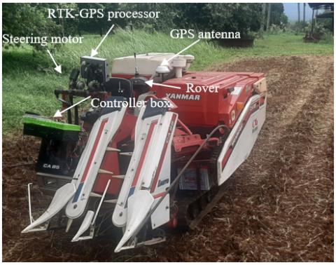
In this study, the manual combine harvester is modified, so it can be operated autonomously. The base machine used for development is a two-row head-feeding combine 14 HP. In Indonesia, rice is planted in rows spaced 0.2 – 0.3 m based on the variety, so the cutting width of 0.68 m can harvest 2 – 3 rows. Figure 1 shows an autonomous combine image equipped with an RTK-GPS, gyroscope, and two DC motors. RTK-GPS system comprises several components: the baseline antenna, GPS antenna, rover antenna, and a processor unit that processes the antenna signals to determine position. Meanwhile, the controller box comprises several components: Raspberry Pi, Arduino, gyroscope, and DC motors.
Figure 1. The autonomous combine harvester
The maximum speed of the combine harvester is 0.9 m/s. Two DC motors are used to actuate the steering lever. Table 1 shows the specifications of the autonomous combine used in this study.
Table 1. Autonomous combine specifications in this study
|
Dimensions Length, mm Width, mm Height, mm Cutting width, mm |
2660 1470 1440 680 |
|
Crawler track Type Length, mm Width, mm Crawler distance (inner), mm Crawler distance (outer), mm |
Rubber 812 250 410 1070 |
|
Weight, kg |
620 |
2.2 Navigation sensors
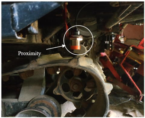
This study's navigation sensors are RTK-GPS and gyroscope sensors (BNO055) which get the combine's absolute and accurate position. According to the datasheet, the RTK-GPS system can give a positioning accuracy up to ± 3 cm and the gyroscope sensor sensitivity of 2000o/s. These navigation sensors measure the position and heading direction, respectively, of the combine at a rate of 5 Hz. Also, a proximity sensor is mounted on the crawler to determine the crawler speed. Figure 2 shows the proximity sensor position. The crawler speed is determined based on the proximity sensor to detect the period. This method is chosen because it is more accurate in measuring at low speeds [13].
Figure 2. Proximity sensor position
2.3 Control system
The schematic diagram of the control system the autonomous combine can be shown in Figure 3. The RTK-DGPS receiver and the gyroscope sensor are connected to a Raspberry Pi through serial communication in real-time. The RTK-DGPS is connected to the USB port, and the gyroscope sensor is connected to the serial pin. A Raspberry Pi receives the GPS and heading data, then it processes to get the desired heading angle. The algorithms are implemented in Python 3.8 to decide actuator movement.
Figure 3. Schematic diagram of the control system
Based on the desired heading angle, Raspberry Pi is ordered actuator motors to pull the steering lever. The steering mechanism's two DC motors are controlled using Arduino's microcontroller with the shaft rotational speed of 40 rpm. Pulling the steering lever causes the crawler rotational speed which can decrease and even stop. The proximity sensors give the crawler speed as feedback of the steering lever. Figure 4 shows the steering mechanism of the steering lever actuator.
The program algorithm starts by input the field dimension (L, W) and land orientation (Ф). The data are used to calculate each path distance. After that, the program reads the GPS and gyroscope data and then calculates it to determine the combine position, heading, travel distance, lateral error, heading error, and heading desired. Based on the heading desired, the system is commanded to move the steering lever. The actual combine position is compared with the turn position or end operation position. If the combine is at the turn position, it turns and going to the next path. Wherever the combine is at the end of operating position, the combine is ordered to stop. Figure 5 presents the algorithmic program of the autonomous combine.
Figure 4. Mechanism of steering lever actuator
Figure 5. Autonomous algorithmic program
2.4 Mathematical model of an autonomous combine
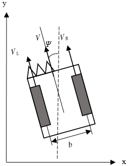
The combine is a crawler-type vehicle using a simple differential-steering two-wheel vehicle model, as shown in Figure 6. Differential speeds between two rubber tracks rectify deviation. Let vL and vR denote the left and right crawler speeds, respectively, and let b represent the wheel tread. If the crawler's slippage is small and can be ignored, then the speed v and yaw $\Psi$ of the combine can be obtained as (1) and (2).
$v=\frac{v_{L}+v_{R}}{2}$ (1)
$\Psi=\tan ^{-1}\left(\frac{v_{L}-v_{R}}{b}\right)=\tan ^{-1}\left(\frac{v_{d}}{b}\right)$ (2)
Figure 6. Differential-steering two-wheel vehicle model
If the position of the vehicle is (xk, yk), the kinematic equation is (3) and (4).
$x_{k+1}=x_{k}+T v_{k} \sin \Psi_{k}$ (3)
$y_{k+1}=y_{k}+T v_{k} \cos \Psi_{k}$ (4)
T is the acquisition cycle of data, vk is the central point's speed, and Ψk is the heading angle.
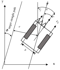
Figure 7. Lateral and heading errors of combine
Figure 7 shows the position (x,y) and heading angle Ψ of the combine in a xy-coordinate system fixed on the ground. Considering that a target path is a straight line, the heading angle α, which is the difference between the heading of the vehicle and the direction of the target path, is obtained by (5), where Φ is the target direction path.
$\alpha=\Psi-\Phi$ (5)
The lateral error e is the distance from the nearest point to the target path. The GPS and gyroscope directly measure the lateral and heading error of the combine.
The combine trajectory control on straight path use (6). Steering control is the desired heading angle δ which is determined from lateral error e, heading error α, and the traveling speed vk. Eq. (6) shows the steering control δ which is determined.
$\delta=k_{1} \tan ^{-1} \frac{e}{R}+k_{2} \alpha$ (6)
where, k1 and k2 are gain constant, and R is the combine forward distance, which is determined by performing preliminary test runs.
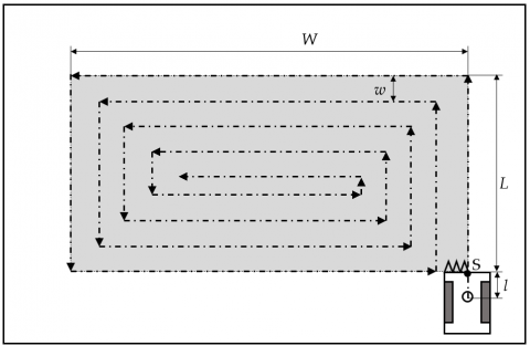
The head-feeding combine used in this study has a driving seat at the right side of its body, and its header and cutting device is shifted to the left side. Hence, the combine should harvest crop along a counter-clockwise path, so the header will be aligned with the rows of the crops. It should be noted from the combine specification that the cutting width is smaller than the combine width. Furthermore, the distance between the edge cut is 0.68 m. GPS antenna in this study is placed on the center point of the combine. Figure 8 shows path planning for the combine in this study. It is assumed that the paddy field is rectangular.
Figure 8. The combine path planning
The grey area is the crop area that will be harvested. Autonomous operation is started on point "S". Before that, to reach the point "S", the combine is operated manually. In the first circle, the combine walks along the crops area length L and width W, then the length L and the width W are reduced by the cutting width w. For the transition to the straight-line path, the combine has to turn left at the corner. The combine stops moving for a moment, then rotates on its axis by 90o. After that, the combine follows the next straight path again.
3.1 Calibration
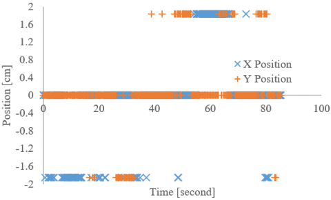
In this section, each sensor was tested for the resulting accuracy. The test comprised an RTK-GPS sensor, a gyroscope sensor, and a crawler speed sensor. Testing the RTK-GPS sensor's accuracy was carried out by recording position data with the combine position at idle. Based on the RTK-GPS accuracy test results, it was found that the result of determining the combine position points on the x-axis and y-axis had an error of ± 1.8 cm. Other than that, the position value received from the RTK-GPS sensor could sometimes show a less tight position with a value of over 1.8 cm from the real value and less than 1.8 cm from the real value. Figure 9 shows the results of the RTK-GPS accuracy test.
Figure 9. Accuracy test of RTK-GPS sensor
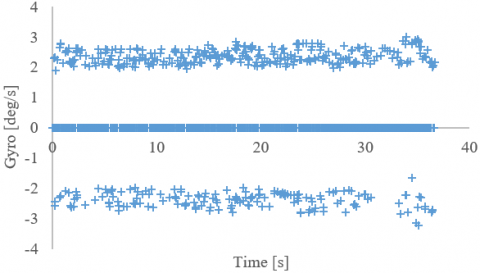
The test on the gyroscope sensor was carried out using the same method. Gyroscope data was recorded for a certain time with the position of the combine at idle. Figure 10 shows the gyroscope accuracy test. This test results show that the gyroscope sensor had an error ± 2.4 o/s. The vibrations generated by the combine most likely cause this error. It occurs because the gyroscope sensor is sensitive to vibration.
Figure 10. Gyroscope accuracy test
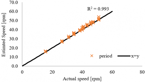
Proximity sensors were used to determine the crawler speed. Figure 11 shows the accuracy-test of this sensor. The results of this test represented that the crawler speed determination had an average error was 1.3 rpm. This error was equivalent to 2.17 cm/s with a gear diameter was 16 cm.
Figure 11. Crawler speed sensor accuracy test
3.2 Preliminary test
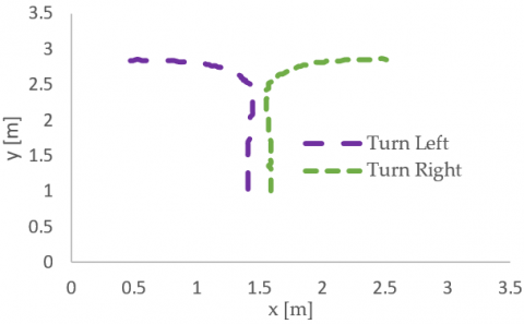
The preliminary test was conducted to know the combine characteristics like average speed, turn radius, and heading rate. In this study, the combine speed was set on low 1 (L1). It resulted in the average speed of combine on 0.1 7 m/s. A low-speed level was chosen because of the steering lever mechanism speed. The steering mechanism needed 0.7 s to pull the steering lever. In this test, the combine traveled on a straight path then the steering level was ordered to pull one of the steering levers. Pull the left steering lever to turn left and pull the right steering lever to turn right. Figure 12 (a) shows the x, y coordinates along with the turn test, and Figure 12 (b) shows the heading results of the turn test.
(a) The x, y coordinates along with the turn test
(b) The heading result of the turn test
Figure 12. The combine turning test
From the turn test, it is known that the combine can rotate 90o on its axis. Besides, it is also informed that the average heading rate of the combine is 8.2 o/s and the turn radius is about 0.4 m.
3.3 Approached test
The approached test was used to know the controller can make the combine reaching the target path. The combine is placed at a certain distance from the right and the left of the straight-line target. The combine heading is positioned parallel to the trajectory angle. Figure 13 shows the result of the approaching test.
This test shows that the combine could reach the straight-line path target. The controller could guide the reference path's combine to reach a distance of about 2.5 m and keep the reference path's trajectory until the path end.
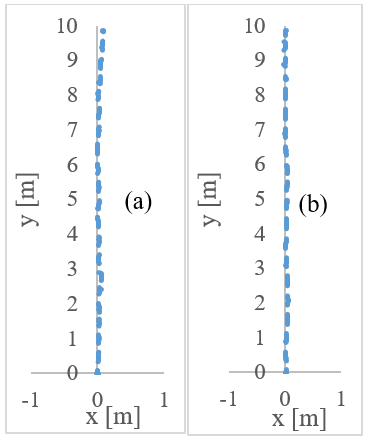
3.4 Straight-line path test
The straight-line path test was carried out to evaluate the combine harvester's ability to follow a straight line as a reference. The combine is placed in the straight path's starting position with the heading angle in the same direction as the trajectory. Then, the combine was ordered to move following the straight path reference. Figure 14 shows the results of the combine testing following a straight-line path. The test results mean that the mean lateral error for the combine position during the 10 m reference path was 0.026 m for the first test (Figure 14.a) and 0.013 m for the second test (Figure 14.b). The largest lateral error is 0.094 m.
Figure 13. The combine controller approach test
Figure 14. The straight-line test
3.5 Harvesting path test
The combine was tested to follow the harvesting path to evaluate the performance. In this test, the combine ran along the field (20 m x 20 m) at a travel speed of 0.17 m/s. The field was used as an empty land without plants. The test area's soil condition had an average moisture content of 28.09 % and an average penetration resistance of 16.3 N/cm2. Figure 15 shows the reference path and actual track of the combine measured by the RTK-GPS.
During this test, the combine harvester follows 42 straight trajectories. The autonomous guideline system processes the GPS and gyroscope data then commands the steering lever mechanism so that the combine can follow the reference path.
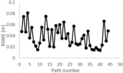
The combine performance could be seen from the lateral error at the trajectory. The lateral error is the perpendicular distance combine position between the reference path. Figure 16 shows the root mean squares (RMS) of the lateral errors for travel along a straight path.
The largest lateral error occurred at the 4th path of 0.081 m, and all the RMS values of the lateral errors were less than 0.1 m. Other studies showed better lateral error values compared to the results of this study, less than 0.05 m [5, 14], but another study also obtained lateral error values of 0.1 m [11]. Several factors that could affect these errors were soil condition at the path, sensors accuracy, vibration, sample rate, time delay introduced by steering lever actuator motors, and the steering lever mechanism.
Figure 15. Reference path and actual track of combine
Figure 16. Root mean squares of the lateral errors on the straight path
In this study, a two-row head-feeding combine harvester was modified into an autonomous combine. An RTK-GPS and a gyroscope were used as navigation sensors to detect the vehicle's position and heading angle. This study shows the developed autonomous combine traverses the reference path with the root mean squares of the lateral errors are less than 0.1 m at the straight path.
In future studies, it is necessary to increase the manoeuvrability of a combine harvester, such as changing the forward and backward motion direction, changing the speed, and determining the cutting height.
This research was financially supported by the Ibn Khaldun Islamic Educational Foundation (YPIKA) Bogor, Indonesia.
[1] Miu, P. (2105). Combine Harvesters: Theory, Modeling, and Design. Boca Raton: CRC Press.
[2] Benson, E.R., Reid, J.F., Zhang, Q. (2003). Machine vision-based guidance system for agricultural grain harvesters using cut-edge detection. Biosyst. Eng., 86(4): 389-398. https://doi.org/10.1016/j.biosystemseng.2003.07.002
[3] Suguri, M., Kouichi, K., Nishiike, Y. (2004). RTK-GPS based autonomous crawler wagon control. Proceedings of the International Conference on Automation Technology for Off-road Equipment, ATOE 2004, pp. 360-368. https://doi.org/10.13031/2013.17853
[4] Tamaki, K., Nagasaka, Y., Nishiwaki, K., Saito, M., Kikuchi, Y., Motobayashi, K. (2013). A robot system for paddy field farming in Japan. IFAC Proceedings Volumes (IFAC-PapersOnline), 46(18): 143-147. https://doi.org/10.3182/20130828-2-SF-3019.00013
[5] Zhang, F., Wu, W., Zhu, Y. (2019). Development of an automated guidance system for tracked combine harvester. IFIP Advances in Information and Communication Technology, 546: 389-399. https://doi.org/10.1007/978-3-030-06179-1_39
[6] Cho, W., Kurita, H., Iida, M., Suguri, M., Masuda, R. (2015). Autonomous positioning of the unloading auger of a combine harvester by a laser sensor and GNSS. Eng. Agric. Environ. Food, 8(3): 178-186. https://doi.org/10.1016/j.eaef.2015.01.004
[7] Choi, J., Yin, X., Yang, L., Noguchi, N. (2014). Development of a laser scanner-based navigation system for a combine harvester. Eng. Agric. Environ. Food, 7(1): 7-13. https://doi.org/10.1016/j.eaef.2013.12.002
[8] Park, B., Lee, J., Kim, Y., Yun, H., Kee, C. (2013). DGPS enhancement to GPS NMEA output data: DGPS by correction projection to position-domain. J. Navig., 66(2): 249-264. https://doi.org/10.1017/S0373463312000471
[9] Sutisna, S.P., Subrata, I.D.M., Setiawan, R.P.A. (2015). Tracking control system of autonomous four wheel tractor on straight path. J. Agritech, 35(1): 106-113. https://doi.org/10.22146/agritech.9425
[10] Huang, J., Tan, H.S. (2006). A low-order DGPS-based vehicle positioning system under urban environment. IEEE/ASME Trans. Mechatronics, 11(5): 567-575. https://doi.org/10.1109/TMECH.2006.882988
[11] Iida, M., Uchida, R., Zhu, H., Suguri, M., Kurita, H., Masuda, R. (2013). Path-following control of a head-feeding combine robot. Eng. Agric. Environ. Food, 6(2): 61-67. https://doi.org/10.1016/S1881-8366(13)80028-6
[12] Rahman, M., Ishii, K. (2018). Heading estimation of robot combine harvesters during turning maneuveres. Sensors, 18(5): 1-12. https://doi.org/10.3390/s18051390
[13] Sutisna, S.P., Setiawan, R.P.A., Subrata, I.D.M., Mandang, T. (2020). Optimation of crawler speeds measurement using inductive proximity for autonomous combine harvester. IOP Conference Series: Earth and Environmental Science, 542(1): 1-6. https://doi.org/10.1088/1755-1315/542/1/012029
[14] Takai, R., Yang, L., Noguchi, N. (2014). Development of a crawler-type robot tractor using RTK-GPS and IMU. Eng. Agric. Environ. Food, 7(4): 143-147. https://doi.org/10.1016/j.eaef.2014.08.004