Yingnan Wang | Yueming Yang | Peiye Zhang | Xuan Zhang*
OPEN ACCESS
The traditional solving algorithms for human attitude face problems like poor stability and low accuracy. To overcome these problems, this paper puts forward a novel human attitude solving algorithm based on fuzzy proportional-integral-derivative (PID) controller and complementary filter, which integrates the data collected by accelerometer, magnetometer and gyro. Through complementary filtering, the error of the gyro was corrected with the aid of accelerometer and magnetometer. Based on the traditional proportional-integral (PI) controller, the fuzzy control was introduced to adjust the parameters in real time, and the differential control (D) was added to improve the dynamic performance of the system, creating a fuzzy PID controller. Then, the fuzzy PID controller was adopted to control the complementary filtering, and the quaternion updating method was employed to compute the human attitude. To verify its effectiveness, our algorithm was compared with the traditional PI filtering algorithm through static and dynamic experiments, using an MPU9150 nine-axis motion tracking device and the MATLAB on the upper computer. The experimental results show that our algorithm achieved stable and accurate output of attitude angles. The research findings are of great application potential in rehabilitation therapy, virtual reality (VR) and human-computer interaction (HCI).
attitude solution, quaternion, complementary filter, fuzzy proportional-integral-derivative (PID) controller
Human attitude recognition is the key to the restoring the position of joints. It is critical to attitude description and behavior prediction. Currently, the attitudes of human body are mainly identified based on videos shot by cameras or the data captured by inertial sensors. In recent years, the micro-electromechanical system (MEMS) has developed into a mature technique. Therefore, the MEMS-based inertial sensors are widely integrated with accelerometer, magnetometer and gyro into a hybrid system that solves the attitude angles and recognizes human attitude. This hybrid system has been intensively applied in such fields as rehabilitation therapy, virtual reality (VR) and human-computer interaction (HCI) [1]. In the meantime, there is a growing demand for highly accurate and stable methods to recognize human attitude in real time.
At present, the inertial sensor-based attitude recognition mainly solves the attitude angles with Kalman filter, gradient descent filter or complementary filter. Many scholars have studied the solving effect of these filters. For instance, Brigante et al. [2] designed a miniaturized wearable motion capture system based on the MEMS, which uses the extended Kalman filter to fuse the attitude data from the gyro, accelerometer and magnetometer, and thus identifies human attitude in a relatively high accuracy. However, the Kalman filter and its extended versions have a high computing complexity, owing to the numerous matrix calculations.
Rico-Azagra et al. [3] used a quaternion-based complementary filter to integrate the data from the accelerometer and the gyro, and then estimate the attitude of unmanned vehicles. Despite reducing the drift of the dip angle, this estimation approach cannot correct the yaw angle error and is prone to the interference from acceleration.
Focusing on the attitude measurement of moving carriers, Euston et al. [4] combined the gradient descent filter and complementary filter, which have a small computing load, into a low-cost attitude measurement system. The proposed system achieves excellent real-time performance and reduces the burden on the microcontroller unit (MCU).
Metni et al. [5] put forward an algorithm to overcome the error divergence of the MEMS-based gyro in attitude solution, coupling complementary filter and proportional-integral (PI) controller. The problem is that the algorithm parameters cannot be adjusted online.
To solve the problems with the above algorithms, this paper designs an attitude solving algorithm based on fuzzy proportional-integral-derivative (PID) controller and complementary filter. According to the errors obtained by the accelerometer and magnetometer, the filter parameters were adjusted, and the angular velocity outputted by the gyro was corrected in real time, before solving the human attitude. The proposed algorithm is simple and reliable, eliminating the need for accurate modeling of noise or fast processing speed. Thus, it is suitable to be embedded into the microprocessor of inertial measurement modules. The experimental results show that the proposed algorithm can consistently output accurate attitude data. The block diagram of our algorithm is given in Figure 1.
Figure 1. The block diagram of our human attitude solving algorithm
The remainder of this paper is organized as follows: Section 2 describes the human attitude and the principle of attitude solution; Section 3 introduces the philosophy of complementary filtering algorithm; Section 4 develops the attitude solving algorithm based on fuzzy PID controller and complementary filter; Section 5 verifies the proposed algorithm through experiments and analyzes the experimental results; Section 6 wraps up this research with conclusions.
2.1 Selection and establishment of coordinate systems
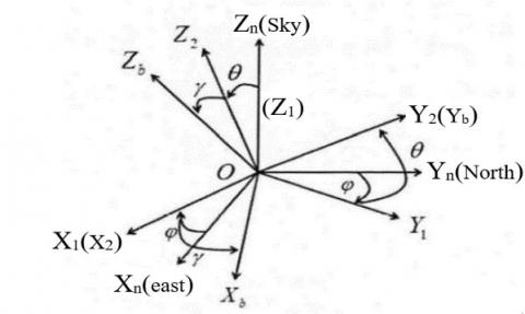
The change of human attitude refers to the spatial rotation of the human coordinate system (CS-b) relative to the reference coordinate system (CS-n).
In the CS-b, the origin lies in the center of gravity of the human body, axis Xb points to the right along the human body, axis Yb points to the horizontal direction of the human body, and axis Zb points to the vertical direction of the human body.
Figure 2. Relationship between human coordinate system and reference coordinate system
In the CS-n, axis Xn points to the east along the local latitude, axis Yn points to the north along the local meridian, and Zn points upwards along the plumb line [6].
The change in human attitude can be described by three angles, namely, the yaw angle ψ, the pitch angle θ and the roll angle φ. The relationship between the two coordinate systems is shown in Figure 2. The mapping between them can be expressed as a rotation matrix [7]:
$\left[\begin{array}{l}{x_{b}} \\ {y_{b}} \\ {z_{b}}\end{array}\right]=c_{n}^{b}\left[\begin{array}{l}{x_{n}} \\ {y_{n}} \\ {z_{n}}\end{array}\right]=\left[\begin{array}{ccc}{\cos \psi \cos \phi-\sin \psi \sin \theta \sin \phi} & {\sin \psi \cos \phi+\cos \psi \sin \theta \sin \phi} & {-\cos \theta \sin \phi} \\ {-\sin \psi \cos \theta} & {\cos \psi \cos \theta} & {\sin \theta} \\ {\cos \psi \sin \phi+\sin \psi \sin \theta \cos \phi} & {\sin \psi \sin \phi-\cos \psi \cos \theta \cos \phi} & {\cos \theta \cos \phi}\end{array}\right]\left[\begin{array}{l}{x_{n}} \\ {y_{n}} \\ {z_{n}}\end{array}\right]$ (1)
2.2 Procedure and principle of quaternion-based solution to human attitude
The attitude angles can be solved based on Euler angle, directional cosine and quaternion. The Euler angle method has a singularity (Gimbal lock) in the solving process, failing to solve the entire attitude. The directional cosine method faces an excessively high computing load, which undermines its real-time performance. By contrast, the quaternion method boasts a small amount of calculation and no singularity, and thus satisfies the requirements of real-time full attitude solution. Therefore, this paper adopts the quaternion method to solve the attitude angles of the human body [8]. Quaternion, consisting of four parts, is a mathematical tool to describe the rotation of a rigid body:
$q={{q}_{0}}+{{q}_{1}}\overset{\to }{\mathop{i}}\,+{{q}_{2}}\overset{\to }{\mathop{j}}\,+{{q}_{3}}\overset{\to }{\mathop{k}}\,$ (2)
The relationship between CS-n, CS-b and quaternion q can be expressed as:
$\left[\begin{array}{l}{x_{b}} \\ {y_{b}} \\ {z_{b}}\end{array}\right]=C_{n}^{b}\left[\begin{array}{l}{x_{n}} \\ {y_{n}} \\ {z_{n}}\end{array}\right]=\left[\begin{array}{ccc}{q_{0}^{2}+q_{1}^{2}-q_{2}^{2}-q_{3}^{2}} & {2\left(q_{1} q_{2}+q_{0} q_{3}\right)} & {2\left(q_{1} q_{3}-q_{0} q_{2}\right)} \\ {2\left(q_{1} q_{2}-q_{0} q_{3}\right)} & {q_{0}^{2}+q_{2}^{2}-q_{1}^{2}-q_{3}^{2}} & {2\left(q_{2} q_{3}+q_{0} q_{1}\right)} \\ {2\left(q_{1} q_{3}+q_{0} q_{2}\right)} & {2\left(q_{2} q_{3}-q_{0} q_{1}\right)} & {q_{0}^{2}+q_{3}^{2}-q_{1}^{2}-q_{2}^{2}}\end{array}\right]\left[\begin{array}{l}{x_{n}} \\ {y_{n}} \\ {z_{n}}\end{array}\right]$ (3)
Comparing formulas (1) and (3), we have:
$\left\{ \begin{align} & \psi =-\arctan [\frac{2({{q}_{1}}{{q}_{2}}-{{q}_{0}}{{q}_{3}})}{{{q}_{0}}^{2}+{{q}_{2}}^{2}-{{q}_{1}}^{2}-{{q}_{3}}^{2}})] \\ & \theta =\arcsin [2({{q}_{2}}{{q}_{3}}+{{q}_{0}}{{q}_{1}})] \\ & \phi =\arctan (\frac{2({{q}_{1}}{{q}_{3}}-{{q}_{0}}{{q}_{2}})}{{{q}_{0}}^{2}+{{q}_{3}}^{2}-{{q}_{1}}^{2}-{{q}_{2}}^{2}}) \\ \end{align} \right.$ (4)
Formula (4) shows the interconvertibility between attitude angles and quaternion. As a result, the attitude angles can be obtained, once the quaternion is solved. The quaternion can be obtained by updating the quaternion differential equation:
$\overset{\centerdot }{\mathop{q}}\,=Rq$ (5)
where, R is the matrix of the angular velocities of CS-b relative to each axis of the CS-n:
$R=\left[ \begin{matrix} 0 & -{{{w}_{x}}}/{2}\; & -{{{w}_{y}}}/{2}\; & {-{{w}_{z}}}/{2}\; \\ {{{w}_{x}}}/{2}\; & 0 & {{{w}_{z}}}/{2}\; & {-{{w}_{y}}}/{2}\; \\ {{{w}_{y}}}/{2}\; & {-{{w}_{z}}}/{2}\; & 0 & {{{w}_{x}}}/{2}\; \\ {{{w}_{z}}}/{2}\; & {{{w}_{y}}}/{2}\; & {-{{w}_{x}}}/{2}\; & 0 \\\end{matrix} \right]$ (6)
where, wx, wy and wz are the angular velocities outputted by the gyro [9]. The quaternion can be updated after determining its initial value and the angular velocities outputted by the gyro at each moment. Then, the attitude angles can be derived from the updated quaternion.
During human attitude detection, the acceleration is measured by an accelerometer. The dip angle is calculated based on the instantaneous value. This measurement method enjoys good steady state performance, but faces relatively large error and poor dynamic performance. Meanwhile, the angular velocity is captured by the gyro, which integrates the angular velocity to obtain the turning angle. Despite its good dynamic performance, the gyro measurement has poor steady state performance due to the accumulation of integral drift errors.
To overcome the above defects, the complementary filtering algorithm is often adopted to improve the attitude measurement in dynamic and steady states. The term “complementary” refers to the correcting of the drift errors of the gyro based on the accelerometer output [10, 11]. The term “filtering” means the necessity to filter out the high-frequency signals of the accelerometer and the low-frequency signals of the gyro, depending on the frequency features of the two sensors.
The algorithm is implemented by computing the difference between the angle solved by the accelerometer and that integrated by the gyro, and using the difference to correct the gyro. Through the correction, the angles outputted by the two sensors will tend to be consistent. Note that the above correction strategy can only correct the pitch and roll angles, and a magnetometer is required to compensate for the yaw angle.
3.1 Accelerator-based compensation
In different coordinate systems, the same vector must have the same size and direction. However, the rotation matrix for vector transformation between CS-b and CS-n is obtained from the quaternion before data fusion, which depends on the angular velocity of the gyro. Any integral error of the gyro will lead to an error in the quaternion-based rotation matrix. If a vector is mapped by the erroneous rotation matrix, the mapped value will deviate from the theoretical value in the target coordinate system. Here, the rotation matrix is corrected based on the deviation, and used to modify the quaternion and thus the attitude angles.
In CS-n, the output of gravity acceleration can be expressed as gn=[0 0 1]T. Through the transform by matrix Cb n [12], it can be converted into gb=[vx vy vs]T in CS-b. Meanwhile, the measured value of the accelerometer in CS-b can be expressed as ab=[ax ay az]T. Both gb and ab are downward vectors in CS-b. Theoretically, the two vectors should be of the same size and direction, if there is no error. According to the definition of cross product, the cross product of two identical vectors is zero, and the nonzero cross product is an error. Hence, gb and ab were normalized and then subject to a cross product, producing the compensating error of the gyro ea:
$\begin{align} & {{\overrightarrow{e}}_{a}}=\overrightarrow{{{g}_{b}}}\times \overrightarrow{{{a}_{b}}}=\left| \begin{matrix} \overrightarrow{i} & \overrightarrow{j} & \overrightarrow{k} \\ {{v}_{x}} & {{v}_{y}} & {{v}_{z}} \\ {{a}_{x}} & {{a}_{y}} & {{a}_{z}} \\\end{matrix} \right|= \\ & ({{v}_{y}}{{a}_{z}}-{{v}_{z}}{{a}_{y}})\overrightarrow{i}-({{v}_{x}}{{a}_{z}}-{{v}_{z}}{{a}_{x}})\overrightarrow{j}+({{v}_{x}}{{a}_{y}}-{{v}_{y}}{{a}_{x}})\overrightarrow{k} \\ \end{align}$ (7)
${{e}_{a}}=\left| \begin{matrix} {{e}_{ax}} \\ {{e}_{ay}} \\ {{e}_{az}} \\\end{matrix} \right|=\left| \begin{matrix} {{v}_{y}}{{a}_{z}}-{{v}_{z}}{{a}_{y}} \\ -({{v}_{x}}{{a}_{z}}-{{v}_{z}}{{a}_{x}}) \\ {{v}_{x}}{{a}_{y}}-{{v}_{y}}{{a}_{x}} \\\end{matrix} \right|$ (8)
3.2 Magnetometer-based compensation
Since the accelerometer cannot sense the rotational movement on the Z-axis, a magnetometer is needed to further compensate for the yaw angle. The error of the magnetometer can be obtained similarly to that of the accelerometer [13]:
$\begin{align} & \overrightarrow{{{e}_{m}}}==\left| \begin{matrix} \overrightarrow{i} & \overrightarrow{j} & \overrightarrow{k} \\ {{w}_{x}} & {{w}_{y}} & {{w}_{z}} \\ {{m}_{x}} & {{m}_{y}} & {{m}_{z}} \\\end{matrix} \right|=({{w}_{y}}{{m}_{z}}-{{w}_{z}}{{m}_{y}})\overrightarrow{i} \\ & -({{w}_{x}}{{m}_{z}}-{{w}_{z}}{{m}_{x}})\overrightarrow{j}+({{w}_{x}}{{m}_{y}}-{{w}_{y}}{{m}_{x}})\overrightarrow{k} \\ \end{align}$ (9)
${{e}_{m}}=\left| \begin{matrix} {{e}_{mx}} \\ {{e}_{my}} \\ {{e}_{mz}} \\\end{matrix} \right|=\left| \begin{matrix} {{w}_{y}}{{m}_{z}}-{{w}_{z}}{{m}_{y}} \\ -({{w}_{x}}{{m}_{z}}-{{w}_{z}}{{m}_{x}}) \\ {{w}_{x}}{{m}_{y}}-{{w}_{y}}{{m}_{x}} \\\end{matrix} \right|$ (10)
where, w is the output in CS-b obtained through Cb n matrix transform of the ideal output in CS-n; m is the normalized value measured by the magnetometer in CS-b.
The magnetometer-based compensation only corrects the yaw angle. The total compensating error of the gyro value can be obtained by adding up the compensating errors obtained based on accelerometer and magnetometer [14]:
${{e}_{r}}={{e}_{a}}+{{e}_{m}}$ (11)
In the traditional complementary filtering algorithm, the total compensating error is imported to the PI controller [15]:
$u(k)={{k}_{p}}{{e}_{r}}(k)+{{k}_{i}}\sum\limits_{j=0}^{k}{{{e}_{r}}(j)}$ (12)
Then, the corrected angular velocity can be obtained:
$w={{w}_{g}}+ku(k)$ (13)
where, wg is the output of the gyro. The corrected wx, wy and wz are substituted to formula (6) to solve the pitch angle, roll angle and yaw angle.
The effectiveness of the complementary filtering algorithm hinges on the selection of the proportional gain kp and the integral gain ki. When the carrier is stationary or moving at low acceleration, a large kp can be selected; otherwise, a small or even zero kp should be adopted. The ki mainly controls the time for the filter to eliminate errors.
Under the effects of various factors (e.g. the wearing of the sensor, the interference from the magnetic field and the periodic adjustment of error), the attitude data may fluctuate, adding to the instability of the solved attitude angles. To prevent the instability, the differential control (D) was introduced to from a PID controller, aiming to improve the dynamic performance, and suppress the changes of deviation in any direction.
In addition, the PID controller was integrated with fuzzy control, creating a fuzzy PID controller (Figure 3) that can adaptively adjust its parameters online [16, 17]. The parameters are adjusted in the following manner: First, find the fuzzy correlations of the three parameters of the PID with the error e(k) and error change rate $\Delta$e(k). Then, continuously check e(k) and $\Delta$e(k) in the course of operation. After that, adjust the three parameters online under the fuzzy control rules, to suit the latest e(k) and $\Delta$e(k). Here, e(k) stands for the total compensating error er in formula (11), and $\Delta$e(k) is the difference between the current error and the previous error.
Figure 3. Structure of the fuzzy PID controller
4.1 Rules of fuzzy PID parameter tuning
Under different e(k) and $\Delta$e(k), the proportional, integral and derivative gains (kp, kiand kd) are auto-tuned by the following rules:
(1) If |e(k)| is large, maintain a large kp and a small kd (to speed up system response) and ensure ki=0 (to avoid excessive overshoot).
(2) If |e(k)| is moderate, there are three different cases:
(a) If |$\Delta$e(k)| is large, maintain a large kp and a small differential term td;
(b) If |$\Delta$e(k)| is moderate, maintain a small kp (to reduce overshoot) and a small td;
(c) If |$\Delta$e(k)| is small, maintain a small kp (to speed up system response) and a suitable td.
(3) If |e(k)| is small, maintain a large kp and a large ki (to enhance the steady state performance of system response), and keep a suitable kd (to prevent oscillation near the equilibrium point).
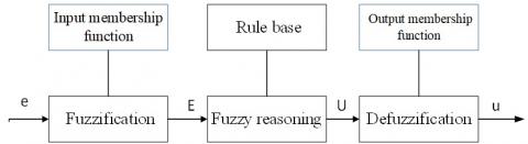
4.2 Design of fuzzy PID controller
The fuzzy controller (Figure 4) mainly consists of three modules: fuzzification, fuzzy reasoning, and defuzzification [18].
Figure 4. Structure of the fuzzy PID controller
(1) Fuzzification
Fuzzification is to map each input to a normalized interval, and obtain the membership of the input for each fuzzy subset, according to the quantization result. The quantization function is required to correspond the specific values of e(k) and △e(k) with fuzzy subsets. To determine the quantization function, the domain corresponding to the fuzzy subset of e(k) and △e(k) is defined as {-6, -5, -4, -3, -2, -1,0,1, 2, 3, 4, 5, 6}. For any measured signal for a physical quantity, there is a measuring range [Vmin, Vmax]. Then, the quantization function can be expressed as:
${{f}_{1}}=\frac{6\times e(k)}{{{V}_{\max }}-{{V}_{\min }}}$
${{f}_{2}}=\frac{6\times \Delta e(k)}{2({{V}_{\max }}-{{V}_{\min }})}$
(2) Fuzzy reasoning
Table 1. Fuzzy control rules
|
e(k) |
△e(k) |
||||||
|
NB |
NM |
NS |
ZO |
PS |
PM |
PB |
|
|
NB |
NB |
NB |
NB |
NM |
NM |
NS |
ZO |
|
NM |
NB |
NB |
NM |
NM |
NS |
ZO |
ZO |
|
NS |
NB |
NM |
NM |
NS |
ZO |
PS |
PM |
|
ZO |
NM |
NM |
NS |
ZO |
PS |
PM |
PM |
|
PS |
NS |
NS |
ZO |
PM |
PM |
PM |
PM |
|
PM |
ZO |
ZO |
PM |
PB |
PB |
PB |
PB |
|
PB |
ZO |
PS |
PM |
PM |
PB |
PB |
PB |
Suppose PM=12 and PB=18. If e(k)=17, then the membership of e(k) for PM is 18-17/18-12=1/6, and the membership e(k) for PB is 17-12/18-12=5/6. The membership is positively correlated with the proximity between e(k) and each fuzzy subset. If e(k) is greater than PB, then the membership of e(k) for PB is 1. The membership of $\Delta$e(k) can be computed in a similar manner.
Based on the fuzzy control rules [20], it is assumed that e(k) belongs to fuzzy subsets PM and PB with a membership of a and 1-a, respectively, and that $\Delta$e(k) belongs to fuzzy subsets NB and NM with a membership of b and 1-b, respectively. From the membership of e(k) for PM and that of $\Delta$e(k) for NB, the membership of the output for ZO can be obtained as a *(1-b). Similarly, the memberships of the output for ZO in the other two combinations are a*b and (1-a)*(1-b), and the membership of the output for PS is (1-a)*b. To sum up, the total membership of the output for ZO is a* b+a*(1-b)+(1-a)*(1-b), and the membership of the output for PS is (1-a)*b.
(3) Defuzzification
The output can be divided into seven parts according to the seven fuzzy subsets: NB, NM, NS, ZO, PS, PM, PB. Based on the results of the previous step, the output can be solved by multiplying the memberships with the values of the corresponding fuzzy subsets: (a*b+a*(1-b)+(1-a)*(1-b))* ZO+(1-a)*b*NS. This marks the end of the fuzzy control.
Our experiments were carried out on an MPU9150 nine-axis motion tracking device, which integrates an MPU6050 inertial sensor (including a three-axis accelerometer and a three-axis gyro) and an HMC5883L three-axis magnetometer. The collected data were transmitted via an I2C bus to the MATLAB software in the upper computer. The output data of the tracking device were processed by our algorithm to obtain the human attitude.
5.1 Static experiment
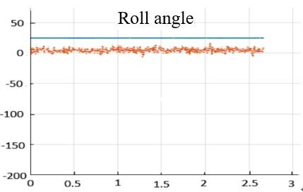
Figure 5. Results of the static experiment
Both the traditional PI filtering algorithm and our fuzzy PID complementary filtering algorithm were adopted to process the output data of the MPU9150 motion tracking device on MATLAB [21]. The static attitudes obtained by the two algorithms are shown in Figure 5, where the abscissa is time (s) and the ordinate is degrees (°).
As shown in Figure 5, in the static state, our algorithm can effectively suppress the drift in any of the three attitude angles and maintain a good stability.
5.2 Dynamic experiment
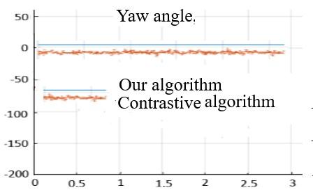
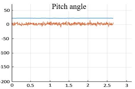
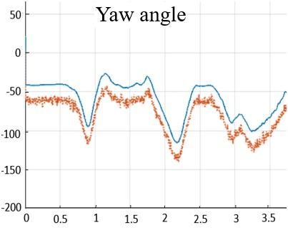
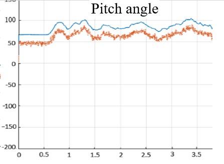
During the dynamic experiment, the inertial measurement module was fixed at the waist of the subject, who was asked to walk at a variable speed. The data of the traditional PI filtering algorithm and our fuzzy PID complementary filtering algorithm were read at the same time via the serial port. The experimental results are displayed in Figure 6.
Figure 6. Results of the dynamic experiment
Through comparison, it is learned that our algorithm effectively reduced the effects of random noises, such as mechanical vibration, acceleration, and magnetic field interference during the movement. In the dynamic state, our algorithm can rapidly track the attitude changes in real time and high accuracy.
This paper improves the traditional complementary filtering algorithm for attitude solving, and designs a human attitude solving algorithm based on fuzzy PID controller and complementary filter. In our algorithm, both complementary filtering and fuzzy PID control are adopted to correct the error of the gyro, and solve human attitude through the corrections based on accelerometer and magnetometer. Experimental results show that our algorithm can output accurate attitude data in a stable manner, and outperform the traditional PI filtering algorithm in response speed and stability. Our research provides a fast and precise tracking method for attitude angles.
This work is supported by Science and Technology Development Project of Jilin Province (Grant No.: 20190304128YY).
[1] Gade, K. (2018). Inertial navigation-theory and applications. Norwegian: Norwegian University of Science and Technology. http://hdl.handle.net/11250/2491714
[2] Brigante, C.M., Abbate, N., Basile, A., Faulisi, A.C., Sessa, S. (2011). Towards miniaturization of a MEMS-based wearable motion capture system. IEEE Transactions on Industrial Electronics, 58(8): 3234-3241. https://doi.org/10.1109/TIE.2011.2148671
[3] Rico-Azagra, J., Gil-Martínez, M., Rico-Azagra, R., Maisterra, P. (2016). Low-cost attitude estimation for a ground vehicle. Robot 2015: Second Iberian Robotics Conference: Advances in Robotics, pp. 121-132. https://doi.org/10.1007/978-3-319-27146-0_10
[4] Euston, M., Coote, P., Mahony, R., Kim, J., Hamel, T. (2008). A complementary filter for attitude estimation of a fixed-wing UAV. 2008 IEEE/RSJ International Conference on Intelligent Robots and Systems, Nice, France, pp. 340-345. https://doi.org/10.1109/IROS.2008.4650766
[5] Metni, N., Pflimlin, J., Hamel, T., Soueres, P. (2005). Attitude and gyro bias estimation for a flying UAV. 2005 IEEE/RSJ International Conference on Intelligent Robots and Systems, Edmonton, Canada, pp. 1114-1120. https://doi.org/10.1109/IROS.2005.1544997
[6] Yoo, T.S., Hong, S.K., Yoon, H.M., Park, S. (2011). Gain-scheduled complementary filter design for a MEMS based attitude and heading reference system. Sensors, 11(4): 3816-3830. https://doi.org/10.3390/s110403816
[7] Nourmohammadi, H., Keighobadi, J. (2018). Fuzzy adaptive integration scheme for low-cost SINS/GPS navigation system. Mechanical Systems and Signal Processing, 99: 434-449. https://doi.org/10.1016/j.ymssp.2017.06.030
[8] Kottath, R., Narkhede, P., Kumar, V., Karar, V., Poddar, S. (2017). Multiple model adaptive complementary filter for attitude estimation. Aerospace Science and Technology, 69: 574-581. https://doi.org/10.1016/j.ast.2017.07.011
[9] Coopmans, C., Jensen, A.M., Chen, Y. (2014). Fractional-order complementary filters for small unmanned aerial system navigation. Journal of Intelligent & Robotic Systems, 73(1-4): 429-453. https://doi.org/10.1007/s10846-013-9915-6
[10] Euston, M., Coote, P., Mahony, R., Kim, J., Hamel, T. (2007). A complementary filter for attitude estimation of a fixed-wing UAV with a low-cost imu. In 6th International Conference on Field and Service Robotics, 1-6.
[11] Mahony, R., Hamel, T., Pflimlin, J.M. (2008). Nonlinear complementary filters on the special orthogonal group. IEEE Transactions on Automatic Control, 53(5): 1203-1217. https://doi.org/10.1109/TAC.2008.923738
[12] Tarhan, M., Altuğ, E. (2011). EKF based attitude estimation and stabilization of a quadrotor UAV using vanishing points in catadioptric images. Journal of Intelligent & Robotic Systems, 62(3-4): 587-607. https://doi.org/10.1007/s10846-010-9459-y
[13] Jing, X., Cui, J., He, H., Zhang, B., Ding, D., Yang, Y. (2017). Attitude estimation for UAV using extended Kalman filter. In 2017 29th Chinese Control and Decision Conference (CCDC), pp. 3307-3312. https://doi.org/10.1109/CCDC.2017.7979077
[14] Euston, M., Coote, P., Mahony, R., Kim, J., Hamel, T. (2008). A complementary filter for attitude estimation of a fixed-wing UAV. In 2008 IEEE/RSJ International Conference on Intelligent Robots and Systems, pp. 340-345. https://doi.org/10.1109/IROS.2008.4650766
[15] Pogorelaya, D.A., Smolovik, M.A., Volkovskiy, S.A., Mikheev, M.A., Aleynik, A.S., Strigalev, V.E. (2017). Adjustment of PID controller in fiber-optic gyro feedback loop. Gyroscopy and Navigation, 8(3): 235-239. https://doi.org/10.1134/S2075108717030075
[16] Sahu, B.K., Pati, S., Mohanty, P.K., Panda, S. (2015). Teaching–learning based optimization algorithm based fuzzy-PID controller for automatic generation control of multi-area power system. Applied Soft Computing, 27: 240-249. https://doi.org/10.1016/j.asoc.2014.11.027
[17] Kasemi, B., Muthalif, A.G., Rashid, M.M., Fathima, S. (2012). Fuzzy-PID controller for semi-active vibration control using magnetorheological fluid damper. Procedia Engineering, 41: 1221-1227. https://doi.org/10.1016/j.proeng.2012.07.304
[18] Ding, Z., Zhou, Y., Zhou, M. (2017). Modeling self-adaptive software systems by fuzzy rules and Petri nets. IEEE Transactions on Fuzzy Systems, 26(2): 967-984. https://doi.org/10.1109/TFUZZ.2017.2700286
[19] Duan, X.G., Li, H.X., Deng, H. (2012). Robustness of fuzzy PID controller due to its inherent saturation. Journal of Process Control, 22(2): 470-476. https://doi.org/10.1016/j.jprocont.2011.12.001
[20] Tao, Y., Xie, G., Chen, Y., Xiong, H., Liu, H., Zheng, J., Gao, J. (2016). A PID and fuzzy logic based method for Quadrotor aircraft control motion. Journal of Intelligent & Fuzzy Systems, 31(6): 2975-2983. https://doi.org/10.3233/JIFS-169182
[21] Huang, W., Liu, C. (2016). Design and simulation of the digital controller of digital closed loop fiber optic gyroscope based on Matlab. 2016 IEEE International Conference on Mechatronics and Automation, Harbin, China, pp. 387-391. https://doi.org/10.1109/ICMA.2016.7558594