Haibing Yuan
OPEN ACCESS
This paper designs a portable instrument for automobile wheel measurement, and details the measurement method and the hardware and software structures. Taking LPC2294 as its microcontroller, the instrument runs on the operating system uC/OS-II, adopts the graphical interface system MiniGUI, and uses multiple sensors. The main functions of the instrument include the measurement of the runout and press-fit depth and the harmonic analysis. The modular structure makes the instrument easy to move and carry. The instrument can be applied to measure various types of automobile wheels and enjoys a broad application potential.
portable, automobile wheel, runout measurement, harmonic analysis, LPC2294
The dynamic balance of automobiles has attracted a growing attention from the academia [1-2]. For example, Ji et al. [3] measured the flange thickness and rim width of wheel sets online. The existing automobile wheel measuring instruments are mostly produced for specific automated wheel production lines. In 2001, the Multi Measuring Instruments Co., Ltd. designed the measuring instruments for ARC-6142W wheels. In 2003, the German company SAMAG Group launched EXA1224EA wheel measuring equipment. Similarly, Hubei University of Automotive Technology developed a wheel testing line exclusively for the wheels produced by Dongfeng Automotive Wheel Co., Ltd. These measuring devices, targeted at the wheels of midsize trucks or cars, are too bulky to be applied widely in product development, not to mention the production or maintenance of various automobiles in small batches. For automotive service providers, it is impossible to install large wheel measuring devices, which are costly and space-consuming. Currently, professional wheel manufacturers in China, namely, Dongfeng Automotive Wheel Co., Ltd., mostly adopt the coordinate measuring machine (CMM) for wheel measurement in product development. The CMM is complex to operate, technically demanding on operators and extremely time-consuming. To make matters worse, the CMM does not support harmonic analysis [4-6]. The harmonic analysis is an important means to analyze the signals of wheel detection. These signals can be processed by various methods [7-8].
The measurement of wheel runout is another research hotspot. For instance, Borecki et al. [9] set up a group of sensors for wireless measurement of the automotive rim and wheel parameters in lab conditions. Yu et al. [10] developed a parameter detection system for hub axial and radial runout, laying the basis for dynamic balance detection of automobiles. Yang et al. [11] designed an online detection system for hub runout of automobile wheels. Wang et al. [12] researched and applied an online measurement system of tire tread profile in automobile tire production. The above measuring devices are controlled by an industrial computer or a programmable logic controller (PLC), with motors, cylinders and screw rods as transmission devices. These immovable devices only apply to wheel detection of automobile wheel production lines, and target only one type of wheels. Some scholars have put forward automobile wheel measurement instruments based on digital signal processor (DSP) or microcontroller unit (MCU). For example, Feng et al. [13] proposed a wheel dynamic detection system based on STM32. Xiong and Zhuang [14] developed a detection system of wheel hub runout based on DSP. Yao et al. [15] invented a detection system of radial and axial hub runouts. However, these instruments are targeted at fixed types of wheels, and unable to make modular adjustment for different wheels. In addition, it is difficult to move or carry these instruments from place to place.
For the research and design (R&D) department, fully-automatic measurement instruments are not suitable, because the product is not yet finalized. In their eyes, a desirable wheel measurement instrument should be easy to operate, place and assemble, and capable of measuring multiple types of wheels. The quality control department also needs a portable, high-precision and universal wheel measuring instrument. However, there is not any wheel runout measurement instrument on the market that is suitable for multiple types of wheel and easy to carry around. This calls for the development of a novel portable wheel measurement instrument for the R&D, quality control, production and maintenance of various automobiles in small batches.
This paper designs a portable instrument for automobile wheel runout measurement. The technical parameters and runout measurement principles were detailed. The installation positions of displacement sensor and incremental encoder were specified. The author also introduced the modular measurement structure, storage of test data, the design of human-machine interface (HMI), the operation system and the graphical interface. In addition, the author described how to filter the data, measure runout and press-fit depth, and conduct harmonic analysis.
The modular structure should be adopted for the measuring part to tolerate various changes and combinations, such that the instrument can measure wheels positioned both on bolt holes and center holes. The control part should use the instrument chassis structure. The measuring instrument should feature high portability.
The system should be able to measure the axial and radial runouts and press-fit depth of each wheel on the upper and lower sides and support harmonic analysis on the wheel.
The measuring range should cover wheels with the diameter of 300~650mm and the width of 90~360 mm, and reach the precision of 0.001 mm.
3.1 Overall design of hardware
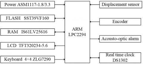
As shown in Figure 1, the instrument hardware consists of an ARM controller, a power supply module, a measurement module, a storage module, a real-time clock module, a keyboard, a liquid-crystal display (LCD) module and an audible and an audiovisual alarm module.
The main controller is Philips LPC2294, a 32-bit microcontroller with the ARM7TDMI core that requires ultra-low power consumption. Inside the controller, there are a 256kB high-speed flash memory, a 16kB static RAM, a 144-pin package, two 32-bit timers, eight 10-bit alternate delivery channels (ADCs), 4 advanced controller area network (CAN) and pulse-width modulation (PWM) channels, and up to nine external interrupts, including 112 general-purpose input output (GPIO) ports. The rich on-chip resources and ultra-low power consumption satisfy the requirements for a portable automobile wheel measuring instrument (hereinafter referred to as the instrument).
The LPC2294 series ARM7 microcontroller uses two power supplies. The power supply at the input/output (I/O) port is 3.3V, and that for the core and its on-chip peripherals is 1.8V. ASM1117-3.3 and ASM11117-1.8 chips were adopted to output power at a stable voltage of 3.3 V and 1.8 V, respectively. The ASM1117 chips can output a current of up to 800mA and control the output voltage accuracy is within ±1%. The current limit and thermal protection ensure the stability of the power supply [16-19].
The measurement module is mainly composed of four displacement sensors and several incremental encoders. Inside the main controller, four of the eight 10-bit ADC channels were connected with the four displacement sensors, for the measurement of wheel runout; meanwhile, the 32-bit counter channel was connected to the encoder to measure the wheel rotation angle and steering.
External expansions like synchronous dynamic random-access memory (SDRAM) and Flash ROM were added to store the large amount of wheel measurement data. The external real-time clock chip DS1302 was installed to record the measuring time of each wheel. A 4×4 keyboard was added for parameter setting. In addition, a 5.6-inch 256-color thin-film-transistor (TFT) LCD was employed to display the runout value and harmonic map of the measured wheel. Moreover, an audiovisual alarm was used to indicate whether a wheel is qualified or not, which is controlled by the GPIO port of LPC2294.
Figure 1. Hardware diagram
3.2 Instrument structure and measurement process
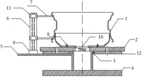
As shown in Figure 2, the instrument, designed to measure the axial and radial runout and press-fit depth of each wheel, contains such four parts as a probe mechanism, a support mechanism, a wheel positioning and locking mechanism and a rotary mechanism. Among them, the wheel positioning and locking mechanism can fix and position different types of wheels after replacing a few parts. With a modular structure, this mechanism is easy to disassemble/assemble and carry.
Note: 1. The target wheel; 2. Wheel positioning part; 3. Cone thrust bearing; 4. Bottom plate; 5. Probe support plate; 6. Probe holder; 7. Sensor rods (one on the upper side and one on the lower side); 8. Fixing bolts; 9. Magnetic probe holder base; 10. Center positioning table; 11. Probe mechanism; 12. Rotary mechanism
Figure 2. Structure of the measuring instrument
During measurement, the target wheel should be fixed onto the wheel positioning part according to the wheel positioning method. Then, the fixing bolts should be installed and the magnetic probe holder base should be adjusted manually, such that the sensor rods cling to the hub measurement position. In this way, the radial and axial turnouts of the upper and lower parts of the wheel are measured by the sensor rods on the upper and lower sides, respectively. Finally, the wheel should be rotated manually to drive the rotation of the rotary mechanism and the wheel positioning part. In this case, the wheel runout is measured by the displacement sensors in the probe holder on the probe support plate and recorded for processing and analysis, while the encoder which rotates with the rotary mechanism performs the angular measurement for the harmonic analysis.
3.3 Sensor layout and measurement method
The sensor module has four displacement sensors and an incremental encoder. The displacement sensors are installed at the end of the two sensor rods, which are fixed to the edges of the upper and lower end faces, to measure the radial and axial runouts of the upper and lower parts of the wheel, including upper and lower end runouts, as well as upper and lower radial runouts. The layout of these sensors is presented in Figure 3 below.
Note: 1. Probe; 2. Sensor rod; 3. Spring; 4. Cross-slide table; 5. Radial displacement sensor; 6. Axial displacement sensor.
Figure 3. Layout of the sensors
During the measurement, the sensor rod should be mounted on the horizontal and vertical cross-slide table so that it can move horizontally and vertically. Then, horizontal displacement caused by the radial runout of the rotating wheel could be measured by radial displacement sensor and the vertical displacement caused by the axial runout could be measured by axial displacement sensor. The contact force in the measurement is provided by the spring. The initial position of the sensor rod could be adjusted to accommodate wheels in different sizes or types. The two sensors should be fitted with protective covers and only the effective travel sections of the sensor rod are allowed to extend beyond the covers.
On this basis, the press-fit depth of the wheel can be calculated from the values measured by the axial displacement sensors in the sensor rods on the upper and lower sides.
Before the harmonic analysis on the wheel, it is necessary to capture the runout of the wheel at different angles in one revolution, that is, the measure the rotation angles. Here, a Fagor S series incremental encoder is adopted for angle measurement, which produces three pulse signals, denoted as A, B and Z, respectively. The A and B pulses have a difference of 90°. The incremental encoder, mounted coaxially with the center of the wheel, outputs 512 pulse signals per turn, creating 512 displacement samples in one revolution of the wheel, i.e. a wheel runout signal every 0.703°.
The encoder could output a Z pulse per revolution at the starting/ending point of rotation, i.e. the null point. If the encoder rotates forward, the A phase of the encoder is half a cycle ahead of the B phase; if it rotates backward, A phase is half a cycle behind the B phase. Thus, the rotation direction can be determined based on the measured positions of the two phases. Likewise, the rotation angle and steering can be measured after the number of A and B pulses was counted by the LPC2294 counting channel. During the collection process, the wheel must rotate in the same direction; otherwise, the data should be recollected from the beginning.
3.4 Sensor signal conversion circuit
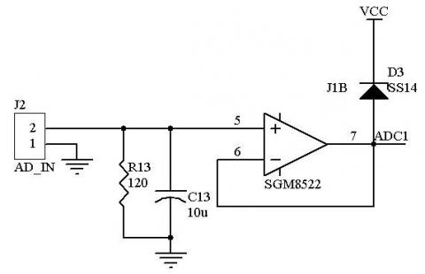
Four inductive displacement sensors with a range of 0~5mm were selected to measure the wheel runout. The output current of each sensor falls between 4 and 20mA. Compared with voltage output sensors, current output sensors boast strong resistance to interference, long transmission distance and stable performance. Before analog-to-digital (AD) conversion, the signals are converted into voltage signals by the circuit in Figure 4. The conversion circuit has a 120 Ω sampling resistor R13 and a voltage follower SGM8522. The current signals between 4 and 20 mA are firstly converted into voltage signals between 0.48 and 2.4V by the sampling resistor, then enter the voltage follower built by the SGM8522 operational amplifier, and finally converted in the ADC channel of LPC2294. The pulse signals outputted by the incremental encoder are imported to the counting channel of LPC2294, which counts the rotation angle and steering of the wheel.
Figure 4. Sensor signal conversion circuit
3.5 Data storage module
The man-machine interface and data storage of the instrument take up a lot of storage space. Considering the limited memory in LPC2294, external storages like SDRAM and FLASH ROM were added to the instrument. The former relies on 256K×16 IS61LV25616AL chips for algorithm processing and graphical user interface (GUI) applications of the wheel measuring instrument, while the latter uses 1M×16 SST39VF160 chips to store the instrument parameters and the measured data of each wheel. These parameters include the calibration coefficients of the four displacement sensors, the set height for the press-fit depth of the wheel, and the allowable ranges for the axial and radial runouts of the wheel on the upper and lower sides. In total, the instrument needs to store the measured data of nearly 100 wheels, ranging from the measurement time, runout value, press-fit depth and harmonic data. The IS61LV25616AL and SST39VF160 chips are connected to the LPC2294 microprocessor via a parallel bus.
3.6 Man-machine interface module
The man-machine interface of the instrument is made up of an LCD display, a keyboard and an audiovisual alarm.
The instrument uses a TFT320234-5.6 256 color LCD screen produced by Wuhan Zhongxian Technology Co., Ltd. With a resolution of 320×234, the 5.6-inch 256 color TFT screen is connected to the single chip microcomputer via 8-bit parallel buses. The data bus is D [7: 0] and the address bus A [1: 0], chip select/CS, read/RD and write /WR. During the measurement, the LCD screen displays the set parameters, measurement status, measured values, statistical charts and harmonic map of the target wheel.
A 4×4 keyboard was included to input parameters, which is achieved by the ZLG7290 chip. The parameters include the standard height for the press-fit depth of the wheel, the acceptable range for the axial and radial runouts of the wheel on the upper and lower sides and the statistical range. The chip is connected to a 3.3V power supply via an I2C serial bus. The reset pin is connected to the LPC2294 reset signal. When the power and ZLG7290 are reset simultaneously, the keyboard interrupt output signal INT is connected to the interrupt pin P0.30 of LPC2294. If the button is pressed, ZLG7290 will output an interrupt signal, causing the interrupt of LPC2294. Through the I2C serial interface, LPC2294 will obtain the corresponding key code.
A light-emitting diode (LED) buzzer was used to indicate whether the wheel is qualified or not and whether the direction of rotation is incorrect. The indication is directly controlled by the GPIO portal of LPC2294.
The instrument software was arranged in the hierarchical structure (Figure 5). From down to top, the structure consists of a driver layer, an operating system layer (uC/OS-Ⅱ), a graphical interface system (MiniGUI) and an application layer. The driver layer includes a TFT LCD driver, an ADC driver, an encoder driver, a keyboard driver, a flash memory driver and a real-time clock driver, while the application layer contains functional modules like signal analysis, man-machine interface and data storage [20-23].
Figure 5. Software design of the measuring instrument
4.1 Operating system and graphic interface system
The instrument runs on the uC/OS-Ⅱ, an open-source embedded real-time operating system. During the operation, the operating system first completes the initialization task and configures the hardware and software for the instrument, and then dispatches multiple tasks by priority. These tasks include acquisition, signal processing, data storage and MiniGUI tasks.
For the lack of a graphic interface, the uC/OS-II is realized by the expansion MiniGUI, which can output desirable user interfaces involving text, button, menu and other controls. In the instrument, MiniGUI mainly completes man-machine interaction such as data and waveform display.
4.2 Signal analysis and processing
The signal analysis and processing mainly deal with digital filtering, calculation of runout and press-fit depth and harmonic analysis.
4.2.1 Digital filtering
Interference signals may present in the digital signals converted from the runout signals of the wheel, owing to noises like unsmooth wheel surface and electromagnetic waves on site. This calls for digital filtering before computing the wheel runout. Here, the average filter algorithm is introduced because the interference signals are random and slowly changing due to the manual rotation of the target wheel. Sixteen rounds of AD sampling are triggered at the pulse generation of the encoder. After adding up the samples, the average should be taken as the valid value by shifting right 4 places. This method is fast and effective.
4.2.2 Calculation of runout and press-fit depth
Whenever the encoder rotates for one revolution, it will generate a Z signal. In one revolution, the encoder generates 512 pulse signals and triggers LPC2294 for AD sampling. After digital filtering, 512 valid samples will be acquired from the circumference of the wheel. Then, the maximum and minimum values of the samples should be computed, and the wheel runout be determined by the maximum-minimum difference and the calibration coefficients of the sensors.
As mentioned before, two sets of sensor rods are fixed onto the edges of the upper and lower end faces. Before the measurement, the vertical distance between the two sets of sensor rods is known. Thus, the changes in the upper and lower end faces of different wheels can be measured by the axial displacement sensors in the two sets of sensor rods, before calculating the wheel press-fit depth.
4.2.3 Harmonic analysis
The runout errors of the target wheel are obviously periodic, for the actual contour of the wheel cross section is a complex closed curve. The radial runout of the points on the contour differs from the runout of the end face, and the error changes on a 2π cycle per one circle. Hence, the runout error of the target wheel can be expressed as a Fourier series.
During the measurement, the incremental encoder starts to measure the runout whenever the wheel is rotated by 0.703°. After one circle of measurement, the periodic sequence X (512) can be obtained. On this basis, the harmonic waves of wheel runout errors by fast Fourier transform. In fact, harmonic data are only used for 0 to 4 times in actual measurement.
The first harmonic reflects the wheel center deviation, and the second, the third and higher harmonics demonstrate the form errors of the outer contour shape of the target wheel. The harmonic analysis helps to identify the causes for wheel runout errors, making it possible to adopt proper countermeasures in the production process. In this way, the wheel performance will be more reliable.
4.3 Main interface of detection program
Figure 6 presents the interface of wheel runout detection program. Four parameters are displayed in real time, namely, the upper end runout, upper radial runout, lower end runout and lower radial runout. The parameter values were compared with the preset values to see if the wheel is qualified.
Figure 6. Runout detection interface
To verify the its performance, the proposed instrument was adopted to measure a 3101R1-015 wheel at the ambient temperature of 20℃. For comparison, a GLOBAL775 CMM (precision: 0.001m) was also applied to measure that wheel. The wheel was measured ten times by our instrument and ten times by the CMM. The mean value of the ten measured results was taken as the final result. The measured results of our instrument are compared with those of the CMM in Table 1 below.
As shown in Table 1, the largest measurement error of our instrument, relative to the CMM, is the upper radial runout (0.009mm). In the ten measurements, the difference between the maximum and minimum results of our instrument was 0.01mm, i.e. the measurement error of our instrument was controlled within 0.01mm. The error satisfies the technical requirements of wheel manufacturers for detection instruments.
Table 1. Comparison of measured results between our instrument and the CMM (mm)
|
Item |
Upper end runout |
Upper radial runout |
Lower radial runout |
Lower end runout |
|
CMM |
0.605 |
0.501 |
0.452 |
0.775 |
|
Our instrument |
0.600 |
0.510 |
0.460 |
0.780 |
|
Measurement error |
0.005 |
0.009 |
0.008 |
0.005 |
This paper designs a portable instrument for automobile wheel measurement, and details the measurement method and the hardware and software structures. Taking LPC2294 as its microcontroller, the instrument runs on the operating system uC/OS-II and adopts the graphical interface system MiniGUI. It can measure the runout and press-fit depth of various wheels and support harmonic analysis. The modular structure makes the instrument easy to disassemble and assemble. In addition, the instrument is light in weight and convenient to move and carry. This instrument has been used in the design and quality control departments of Dongfeng Automotive Wheel Co., Ltd. for half a year, during which it demonstrated reliable performance and achieved accurate measurement. In future research, the instrument will be connected to the upper computer so that the measured data can be uploaded for further analysis and shared among design, manufacturing and other departments of the wheel manufacturer.
This study was supported by the Science and Technology Research Foundation of Hubei Education Department(D20151803), the Shiyan Science and Technology Research Foundation (16Y97).
[1] Sureddi, C. (2018). Design, material optimization and dynamic analysis on automobile wheel rim. International Journal of Scientific and Research Publications, 8(11): 83-89. https://doi.org/10.29322/ijsrp.8.11.2018.p8353
[2] Krummenacher, G., Ong, C.S., Koller, S., Kobayashi, S., Buhmann, J.M. (2018). Wheel defect detection with machine learning. IEEE Transactions on Intelligent Transportation Systems, 19(4): 1176-1187. https://doi.org/10.1109/tits.2017.272072
[3] Ji, J.C., Shao, S.Y., Feng, Q.B. (2013). A novel method to measure flange thickness and rim width of wheel sets on line. Applied Mechanics and Materials, 330: 237-241. https://doi.org/10.4028/www.scientific.net/AMM.330.237
[4] Niskanen, A.J., Tuononen, A.J. (2017). Detection of the local sliding in the tyre-road contact by measuring vibrations on the inner liner of the tyre. Measurement Science & Technology, 28(5): 55-57. https://doi.org/10.1088/1361-6501/aa6148
[5] Li, G.X., Zhang, W.L. (2010). Data processing of wheel runout tolerance detector based on harmonic analysis. In 2010 International Conference on Computer, Mechatronics, Control and Electronic Engineering, 2: 414-417. https://doi.org/10.1109/CMCE.2010.5610031
[6] Yang, G., Qin, Y.Z. (2014). Application of harmonic analysis in hub quality classification. China Mechanical Engineering, (10): 59-62. https://doi.org/10.3969/j.issn.1004-132X.2014.10.011
[7] Huang, N.E., Zheng, S., Long, S.R,. Wu, M.C., Shih, H.H., Zheng, Q., Yen, N.C., Tung, C.C., Liu, H.H. (1998). The empirical mode decomposition and the Hilbert spectrum for nonlinear and non-stationary time series analysis. Proc R Soc Lond Ser A, 454: 903-995. https://doi.org/10.1098/rspa.1998.0193
[8] Qin, P., Cai, P. (2007). Application of Improved EMD in dynamic balance signal extraction. Journal of Instrumentation, (1): 103-107. https://doi.org/10.3321/j.issn:0254-3087.2007.01.021
[9] Borecki, M., Prus, P., M.L., Korwin-Pawlowski, M.L., Rychlik, A., Kozubel, W. (2017). Sensor set-up for wireless measurement of automotive rim and wheel parameters in laboratory conditions. Proc. SPIE 10445, Photonics Applications in Astronomy, Communications, Industry, and High Energy Physics Experiments, p. 1044569. https://doi.org/10.1117/12.2280970
[10] Yu, B.J., Wang, X.D., Sun, R. (2006). Research and development of hub axial and radial run out parameter detection system. Mechanical Engineering and Automation, (4): 82-83. https://doi.org/10.3969/j.issn.1672-6413.2006.04.031
[11] Yang, X.D., Men, Y.Z., Yu, L., Gao, J.G. (2015). The design of automobile wheel hub runout online detection system. Applied Mechanics and Materials, 741: 298-301. https://doi.org/10.4028/www.scientific.net/amm.741.298
[12] Wang, P.Y., Chen, X.G., Yang, K., Liu, X.J. (2017). Research and application of online measurement system of tire tread profile in automobile tire production. International Conference on Electronics and Information Engineering. https://doi.org/10.1117/12.2265221
[13] Feng, W.J., Chen, W.M., He, H.L. (2014). Wheel dynamic balance detection system based on STM32. Manufacturing Automation, 36(14): 15-18. https://doi.org/10.3679/j.issn.1002-132X.2014.15.018
[14] Xiong, S.C., Zhuang, S. (2015). Detection system of wheel hub runout based on DSP. Mechatronics Engineering, 32(4): 488-492. https://doi.org/10.3969/j.issn.1001-4551.2015.04.010
[15] Yao, B.C., Xiong, Y.F., Liao, W.Y., Zong, X.L., Rao, J.K., Hu, Z.F. (2001). Wheel steel ring diameter and axial run out detector. Mechanical Manufacturing, (1): 49-50. https://doi.org/10.5148/www.scientific.net/amm.49.50
[16] Ejidokun, T.O., Yesufu, T.K., Ayodele, K.P., Ogunseye, A.A. (2018). Implementation of an on-board embedded system for monitoring drowsiness in automobile drivers. International Journal of Technology, 9(4): 819-827. https://doi.org/10.14716/ijtech.v9i4.1691
[17] Yekini, N.A., Oloyede, A.O., Agnes, A.K., Okikiola, F.M. (2016). Microcontroller-based automobile tracking system with audio surveillance using gps and gsm module. International Journal of Information Engineering and Electronic Business (IJIEEB), 8(3): 41-46. https://doi.org/10.5815/ijieeb.2016.03.05
[18] Belbachir, A. (2017). An embedded testbed architecture to evaluate autonomous car driving. Intelligent Service Robotics, 10(2): 109-119. https://doi.org/10.1007/s11370-016-0213-6
[19] Lee, E.K., Gerla, M., Pau, G., Lee, U., Lim, J.H. (2016). Internet of Vehicles: From intelligent grid to autonomous cars and vehicular fogs. International Journal of Distributed Sensor Networks, 12: 89-99. https://doi.org/10.1177/1550147716665500
[20] Arm, J., Bradac, Z., Kaczmarczyk, V. (2016). Real-time capabilities of Linux RTAI. IFAC PapersOnLine, 49(25): 401-406. https://doi.org/10.1016/j.ifacol.2016.12.080
[21] Tran, D., Do, H.M., Sheng, W., Bai, H., Chowdhary, G. Sheng, W.H., Bai, H. (2018). Real-time detection of distracted driving based on deep learning. IET Intelligent Transport Systems, 12(10): 1210-1219. https://doi.org/10.1049/iet-its.2018.5172
[22] Kaur, P., Sobti, R. (2018). A modelling framework for automotive software design and optimal test path generation. Journal of Intelligent & Fuzzy Systems, 34(3): 1731-1742. https://doi.org/10.3233/JIFS-169466
[23] Gobbi, M., Comolli, F., Hada, M., Mastinu, G. (2019). An instrumented steering wheel for driver model development. Mechatronics, 64: 228-236. https://doi.org/10.1016/j.mechatronics.2019.102285