Karimulla Peerla Shaik* | B. Venkata Prasanth | R. Srinivasa Rao
OPEN ACCESS
In this paper the objective is to solve an optimal power flow problem (OPF) as load varies. It is indeed necessary to know the present operating status of the system for secure operation. A novel Improved Wind driven optimization (IWDO) algorithm is proposed to solve highly nonlinear OPF problem. The standard IEEE–14 bus system is considered for the study. The load variation is considered from base case to 150% of base case. With these load perturbations the voltage deviations and fuel cost variations are observed. From the obtained results it can be observed that, as the load varies from minimum level to maximum the total fuel cost goes on reduces for OPF compared to load flow. At the same time the total voltage drop also high for lower loading levels and reduces as load goes on increases compared to OPF.
load flow, optimal power flow, improved wind driven optimization, voltage deviation, total fuel cost, soft computing technique
The load flow solution is a vital aspect of the power system operation and control. It involves finding the voltage magnitudes and angles at various buses and calculating the power flows in various transmission lines [1]. These are very helpful to decide the slack bus generation after knowing the losses in a system. By knowing all these parameters in a given power system, it facilitates the power system operating engineers to take proper planning and operation decisions for secure operation. There are certain substantiated approaches to solve the power flow solution with reasonably accurate results. Specifying those Gauss seidel (GS), Newton–Raphson (NR), Decoupled and Fast Decoupled (FDLF) methods [2].
As the load varies, the various operating parameters of power system will get change. For satisfactory operation of system, these parameters should be within the prescribed limits. In this paper, the effect of load variation on different electrical parameters is analyzed.
This work is organized as follows. Section 2 presents generalized objectives of OPF, the mathematical modeling of OPF with imposed constraints is demonstrated in section 3. The IWDO algorithm is presented in section 4. Finally, the results and discussions are briefed in section 5.
The OPF problem is to determine the optimal setting of various electrical parameters [3] such that it yields to the optimum result of considered objective/s. mathematically, it can be represented as:
Optimize whether to minimize or maximize the objective function [8-11]
$f(x, u)$
Subjected to the constraints $h(x, u)=0$ and $g(x, u) \leq 0$.
'h' represents the set of equality constraints and 'g' is a set of inequality constraints with ' $x$ and $u$ ' dependent and control variables respectively. The objective may be any one or the combination of the following [4].
(1) Minimizing the operating cost of a power plant.
(2) Minimizing the total transmission losses.
(3) Maximizing the loadability of the existing transmission system.
(4) Minimizing the emission levels of power plant.
Theequality constraints include, real and reactive power balance has to be satisfied. At the same time the inequality constraints include real, reactive power generation and bus voltage limits, tap setting positions of tap changing transformer, Thermal limitation of each line and finally thelimitation on capacitance generated reactive power if exists. In the present work the solution of OPF has been carried out with the objective of minimizing the total running cost [12-15].
The mathematical modeling of present OPF problem [5], which is highly nonlinear, is to minimize the total cost in normal case as well as in contingency case,
Minimize the total fuel cost FTwith NG number of units,
${{F}_{T}}=\,\sum\limits_{i=1}^{NG}{F({{P}_{i}})}$ (1)
The fuel cost function of ith generator, to generate Pi MW is
$F({{P}_{i}})\,=\,{{a}_{i}}\times P_{i}^{2}+{{b}_{i}}\times {{P}_{i}}+{{c}_{i}}\,\,\,Rs/hr$ (2)
where, $a_{i}, b_{i}$ and $c_{i}$ represents the cost coefficients of ith unit.
Subjected to the equality constraints of real and reactive powers.
$\sum\limits_{i=1}^{NG}{{{P}_{i}}}\,=\,{{P}_{D}}+\,{{P}_{L}};\,\,\,\,\,\,\,\,\,\,\,\,\sum\limits_{i=1}^{NG}{{{Q}_{i}}}\,=\,{{Q}_{D}}+\,{{Q}_{L}}$ (3)
The total generation with NGnumber ofunits is equal to sum of total real power demand PD, and total transmission loss PL. Same holds for the reactive power also.
The inequality constraints include active, reactive powers and bus voltages should be within limits.
$P_{i}^{Min}\,\le \,{{P}_{i}}\,\le \,P_{i}^{Max}\,;\,\,\,\,\,\,\,\,Q_{i}^{Min}\,\le \,{{Q}_{i}}\,\le \,Q_{i}^{Max}\,;\,\,\,\,\,\,V_{i}^{Min}\,\le \,{{V}_{i}}\,\le \,V_{i}^{Max}$ (4)
Tapping setting of Tap changing transformer
$T_{i}^{Min}\le \,{{T}_{i}}\,\le \,T_{i}^{Max}$ (5)
The thermal capability of each transmission line in terms of MVA
${{S}_{Li}}\,\le \,S_{Li}^{Max}$ (6)
Limitation on shunt capacitor generated reactive power
$Q_{Ci}^{Min}\,\le \,{{Q}_{Ci}}\,\le \,Q_{Ci}^{Max}$ (7)
The Wind Driven Optimization (WDO) algorithm [6, 16-17] is proposed by inspiring from the natural behavior of the moment of air particles in the atmosphere. The motion of an air particle is influenced by the factors such as frictional forces caused by the neighbor air particles, force due to pressure gradient, forces due to gravity and coriolis forces. The velocity and position of each air particle is governed by the following equation.
${{V}_{t+1}}=(1-\alpha ){{V}_{t}}-g{{x}_{t}}+RT\left| \frac{1}{r}-1 \right|({{x}_{opt}}-{{x}_{t}})+\frac{cu_{t}^{other\dim}}{r}$ (8)
${{x}_{t+1}}={{x}_{t}}+{{V}_{i+1}}$ (9)
IWDO is proposed to obtain the better convergence accuracy with faster rate by adding a new factor known as ‘Wind Factor (Wf)‘to WDO [18]. With the enormous testing on different standard functions, its value is identifies to vary in between 0 to 2. The modified velocity expression is given as [19]:
${{V}_{t+1}}=(1-\alpha ){{V}_{t}}-g{{x}_{t}}+RT\left| \frac{1}{r}-1 \right|({{x}_{opt}}-{{W}_{F}}*{{x}_{t}})+\frac{cu_{t}^{other\dim}}{r}$ (10)
${{x}_{t+1}}={{x}_{t}}+{{V}_{i+1}}$ (11)
The step wise procedure of IWDO described in following steps.
Step 1: Initialize the IWDO attributes.
Step 2: Construct the objective function or pressure function.
Step 3: Generate initial air particle positions and their velocities randomly.
Step 4: Calculate the fitness value of each air particle.
Step 5: The current velocity should be updated using equation 10.
Step 6: Check whether velocity is within limits or not.
Step 7: Update the position of air particle with the help of expression 11.
Step 8: Check whether particle position is within limits or not.
Step 9: Iterate the above procedure until the convergence criteria satisfies.
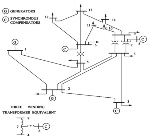
Figure 1. Standard IEEE 14 bus system
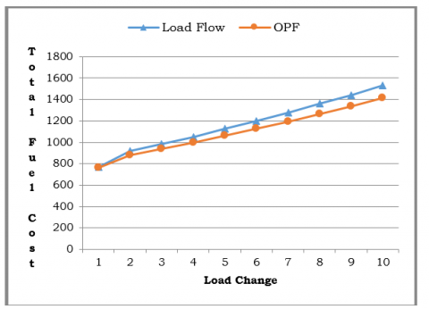
Figure 2. Fuel cost for load flow and OPF with load change
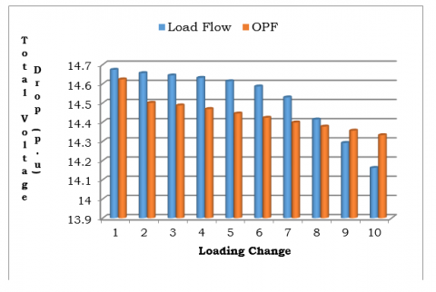
The proposed method is implemented on standard IEEE 14 bus system [7]. It has 1 slack bus, 4 generator bus and 9 load buses with 21 transmission lines.The single line diagram is shown in Fig 1.The simulation has been carried out in two cases. In case (i) load flow problem is solved to know the static behaviour of the system. In case (ii) OPF problem is also solved with the objective of minimizing the cost by imposing the required constraints. Both the cases are executed by varying the load. Finally the two cases results are depicted in Figure 2 and Figure 3. From Figure 2, it can be observed that for lower loading conditions the load flow solution yields to higher total voltage drop. As the loading reaches to higher value, OPF problem yields to larger total voltage drops. From Figure 3, It can be observed that, the load flow results into higher fuel cost compared to optimal power flow as its objective itself is to minimize the fuel cost.
Figure 3. Total voltage drop for load flow and OPF with load change
In this paper a novel improved wind driven optimization algorithm is used to solve optimal power flow problem. The standard IEEE 14 bus system is considered for the analysis. By increasing the load from base value to 150 % of base load, the load flow and OPF has been compared. The total voltage drop and total fuel costs are observed for the two cases. It is concluded that as the objective of OPF is to minimize the fuel cost, as the load increases, the fuel cost of OPF is less compared to load flow. The total voltage drop is less for lower and more for higher load changes. The work can be extended in future by using hybrid and sophisticated soft computing techniques for deregulation system also.
[1] Grainger, J.J., Stevenson, W.D. (2004). Power system Analysis. McGraw-Hill Series in Electrical and Computer Engineering. ISBN: 9780070612938
[2] Idoniboyeobu, D.C., Ibeni, C. (2017). Analysisfor Electical Load Flow Studies in Port Harcourt, Nigeria, Using Newton Raphson Fast Decoupled Techniques. American Journal of Engineering Research, 6(12): 230-240.
[3] Ramesh, G., Kumar, T.K.S. (2016). Optimal power flow-based congestion management inrestructured power systems. International Journal of Power and Energy Conversion, 7(1): 84-96. https://doi.org/10.1504/IJPEC.2016.075067
[4] Suresh, C.V., Sivanagaraju, S. (2015). Increasing the loadability of power system through optimal placement of GUPFC using UDTPSO. Journal of Electrical Systems, 11(1): 61-75.
[5] Dulău, L., Abrudean, M., & Bică, D. (2015). Optimal power flow analysis of a distributed generation system. Procedia Technology, 19: 673-680. https://doi.org/10.1016/j.protcy.2015.02.095
[6] Shaik, K.P., Prasanth, B.V., Rao, R.S. (2017). Optimal siting of UPFC using improved wind driven optimization algorithm. Journal of Advanced Research in Dynamical and Control Systems, 9(14): 1881-1889.
[7] Ara, A.L., Aghaei, J., Alaleh, M., Barati, H. (2013). Contingency-based optimal placement of Optimal Unified Power Flow Controller (OUPFC) in electrical energy transmission systems. Scientia Iranica, 20(3): 778-785. https://doi.org/10.1016/j.scient.2013.04.007
[8] Immanuel, A., Chengaiah, C. (2015). A comprehensive literature survey on recent methods of optimal power flow. IOSR Journal of Electrical and Electronics Engineering, 10(5): 1-12. https://doi.org/10.6084/m9.figshare.1577429.v1
[9] Chandekar, A.D., Subroto, D. (2015). A Research on Optimal Power Flow Solutions For Variable Load. International Journal of Engineering Research and Applications, 5(1): 84-88.
[10] Bhavani, S.V.D., Kumar, K.R. (2014). Novel Genetic Algorithm Based Solutions for Optimal Power Flow under Contingency Conditions. International Journal of Engineering Research and Applications, 4(6): 20-30.
[11] Hariharan, T., Sundaram, K.M. (2016). Optimal power flow using firefly algorithm with unified power flow controller. Circuits and Systems, 7: 1934-1942. https://doi.org/10.4236/cs.2016.78168
[12] Rahman, M.K., Alam, S.M., Hossain, Z.M., Shahjahan, M. (2014). Localization of FACTS devices for optimal power flow using genetic algorithm. 2013 International Conference on Electrical Information and Communication Technology (EICT) during, 13-15. https://doi.org/10.1109/EICT.2014.6777889
[13] Vanitha, R., Baskaran, J., Sudhakaran, M. (2015). Multi Objective Optimal Power Flow with STATCOM using DE in WAFGP. Indian Journal of Science andTechnology, 8(2): 191–198. https://doi.org/10.17485/ijst/2015/v8i1/56654
[14] Wibowo, R.S., Fathurrodli, T.P., Penangsang, O., Soeprijanto, A. (2014). Security constrained optimal power flow with FACTS devices using bender decomposition. TENCON 2014 - 2014 IEEE Region 10 Conference. https://doi.org/10.1109/TENCON.2014.7022379
[15] Ara, A.L., Aghaei, J., Alaleh, M., Barati, H. (2013). Contingency-based optimal placement of Optimal Unified Power Flow Controller (OUPFC) in electrical energy transmission systems. Scientia Iranica, 20(3): 778-785. https://doi.org/10.1016/j.scient.2013.04.007
[16] Bhesdadiya R.H., Patel, C.R., Patel, R.M. (2014). Transmission Line Loadability Improvement Using Facts Device. IJRET: International Journal of Research in Engineering and Technology, 3(5): 626-630. https://doi.org/10.15623/ijret.2014.0305115
[17] Sakthidasan, K., Vasudevan, N., Diderot, P.K.G., Kadhiravan, C. (2019). WOAPR: An affinity propagation based clustering and optimal path selection for time-critical wireless sensor networks. IET Networks, 8(2): 100-106. https://doi.org/10.1049/iet-net.2018.5081
[18] Saranya, A., Selvam, N. (2018). Improving Transmission Line Loadability Limits Using IPFC. IJARIIE, 4(3): 677-689.
[19] Reddy, M.L., Reddy, V.C.V. (2017). Analyzing the Effect of Loadability in the presence of TCSC &SVC. IJIRSET, 6(4): 5273–5287. https://doi.org/10.15680/IJIRSET.2017.0604024