Azzouz Tamaarat
OPEN ACCESS
This paper presented a system consists of wind turbine operating under the wind speed change, doubly fed induction generator (DFIG) connected directly to the constant grid by the stator and fed by a power converter on the rotor side. Vector control is used to independently control the flow of active and reactive power between the stator of the (DFIG) and the grid, which in this paper is realized, with conventional PI, fuzzy logic and fuzzy self-tuning PI controllers. The proposed controllers generate the references rotor voltages required to guarantee active and reactive power reach their desired reference values. Modeling and simulation of system using MATLAB and their behavior has been examined with simulations. The dynamics of the system is analyzed under varying wind speed, this analysis is focused on the active and reactive power control. The results obtained from PI controller, fuzzy and Fuzzy self tuned PI controllers are compared to validate the advantages of the proposed intelligent controllers based on fuzzy systems.
doubly-fed induction generator, active power, reactive power, proportion integration, fuzzy logic
Wind energy is clean and its sources are available free of cost. Approximately, 10 million MW of wind energy is continuously available on the Earth [1]. This type of energy has grown greatly in wind generation in recent years in the world. Kinetic energy from moving air is converted into electricity by wind turbines. Several generic types of generator are possible candidates in wind turbines. Double-Fed Induction Generator (DFIG) is one of them. During recent years variable speed wind turbines with DFIG are the most applied wind turbine. The great interest for variable speed wind turbine is because of very good characteristics with modern semiconductor converters and digital control system. These later endow the DFIG with additional advantages such as stability and flexible control [2].Typical configuration of the wind turbine with DFIG consists of an induction wound rotor generator with stator winding connected directly to the three phase grid and rotor winding connected to the three phase grid by the use of back-to-back power semiconductor converter. The control system of DFIG consists of two control subsystems: control system of power converter connected to the rotor side (RSC) and control system of power converter connected to the electric grid side (GSC). The two converters are controlled with voltage PWM inverter. The rotor-side converter is used to control the behavior of the machine in both sub- and super-synchronous modes as well as tracking the maximum power output characteristic of the wind turbine. The vector control for this converter ensures the decoupling control of stator active and reactive power drawn from the grid [3]. Various types of regulators were used to this control.
For reasons of simplicity, applicability, moderate cost, and adequacy of linear systems, the classical control techniques using the most simple regulator: the proportional-integral (PI, IP) or proportional-integral-derivative (PID) regulator are still the most generally utilized control structure in a large portion of the modern processes [4]. This controller type utilizes several tuning methods for obtaining appropriate control parameters. Among the several methods reported, Ziegler Nichols based tuning method is widely used because of its simple structure [5, 6]. However, it can be difficult to define the suitable PID gains when the plant to be controlled has a high level of complexity, such as, nonlinearities, time delay and structural uncertainties. All these factors could degrade the performance of a PID controller, which becomes unsatisfactory to guarantee the requirements in most of the practical systems [7, 8].
The artificial intelligence approaches have been very popular since the beginning of the 90s. Progressively, they have been utilized to solve any usual and complex control problems [9].
Intelligent control systems (ICS) have the ability to work well when the operation point of the system is changing. Fuzzy logic systems, for example, are able to synthesize information from human experts. Also, artificial neural networks can implement complex non-linear control laws which are automatically derived from the desired input-to-output response mapping of the overall wind turbine system.
In contrast with traditional linear and nonlinear control theory, a fuzzy logic controller (FLC) is not based on a mathematical model [10, 11], is widely used to solve problems under uncertain and vague environments, with high nonlinearities, this type of control is framed on the basis of human logic [10].The use of (FLC) has become popular over the last decade and the development known microcontrollers have also helped in the popularization of this type of controller [11]. The (FLC) provides an algorithm, which converts the expert knowledge into an automatic control strategy. Fuzzy logic is capable of handling approximate information in a systematic way and therefore it is suited for controlling non linear systems and is used for modeling complex systems where an inexact model exists or systems where ambiguity or vagueness is common [12]. Fuzzy logic has been recently applied in process control, modeling, estimation, identification, diagnostics, stock market, prediction, agriculture, military science and so on [13, 14].
The proportional integral PI controller is the most dominant form of automatic controller in industrial use today, PI is not the best controller. It is only the most common controller. The coefficients of this controller are not always tuned for the nonlinear plant with unpredictable parameter variations. With this technique of control, it is necessary to automatically tune the controller parameters according to the nature of the process. For tuning a PI controller have certain limitations. These limitations can be taken care by tuning the PI controller using intelligent techniques such as, fuzzy logic [15-21], artificial neural network [22, 23], adaptive neuro-fuzzy inference system and genetic algorithms [24-26]. The conventional PI controller is combined with a (FLC) in order to achieve better system performance. The fuzzy-based self-tuned PI- Fuzzy controller is a powerful algorithm that can be used when the system is difficult to model, and since the conventional control technique does not provide the expected results even when expert knowledge’s are available. This paper proposes a method to combine conventional PI and fuzzy logic controllers, this proposal bears two major advantages: the strengths of both PI and fuzzy logic controllers are benefited.
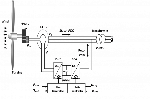
Wind turbine captures the kinetic energy of the wind and converts it into mechanical energy pt then electricity pe. For the wind turbine based on DFIG the electric power ps delivery directly from DFIG stator to the electric grid. The active power transmitted to the grid is the algebraic sum of stator power Ps and rotor power Pr (Figure 1). In wind turbine the stator active and reactive power control of the DFIG is based on the theory of the induction machine vector control. The main duty of RSC is to control DFIG-produced active and reactive powers [27].
Figure 1. Wind turbine control system with DFIG
2.1 Dynamic model of the DFIG
Dynamic model of DFIG can be described by the differential equations system for stator and rotor windings and by the equation of rotor motion equations (1, 2 and 3):
$\begin{align} & {{v}_{sd}}={{R}_{s}}.{{i}_{sd}}+\frac{d{{\varphi }_{sd}}}{dt}-{{\omega }_{s}}.{{\varphi }_{sq}} \\ & {{v}_{sq}}={{R}_{s}}.{{i}_{sq}}+\frac{d{{\varphi }_{sq}}}{dt}+\omega {}_{s}.{{\varphi }_{sd}} \\ & {{v}_{rd}}={{R}_{r}}.{{i}_{rd}}+\frac{d{{\varphi }_{rd}}}{dt}-{{\omega }_{r}}.{{\varphi }_{rq}} \\ & {{v}_{rq}}={{R}_{r}}.{{i}_{rq}}+\frac{d{{\varphi }_{rq}}}{dt}+{{\omega }_{r}}.{{\varphi }_{rd}} \\ \end{align}$ (1)
$\begin{align} & {{\varphi }_{sd}}={{L}_{s}}.{{i}_{sd}}+M.{{i}_{rd}} \\ & {{\varphi }_{sq}}={{L}_{s}}.{{i}_{sq}}+M.{{i}_{rq}} \\ & {{\varphi }_{rd}}={{L}_{r}}.{{i}_{rd}}+M.{{i}_{sd}} \\ & {{\varphi }_{rq}}={{L}_{r}}.{{i}_{rq}}+M.{{i}_{sq}} \\ \end{align}$ (2)
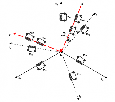
where, Rs, Rr, Ls and Lr are the resistances and leakage inductances of the stator and rotor windings; M is the mutual inductance; vsd, vsq, vrd, vrq , isd, isq, ird, irq, Φsd, Φsq , Φrd and Φrq are the d and q components of the space vectors of stator and rotor voltages, currents, and fluxes; ωs and ωr are the angular frequencies of stator and rotor currents.
where: ωs = ωr + pΩ
Ω is the rotational speed of the rotor and p is the pair pole number.
Figure 2. Orientation of the (d, q) frame
The system dynamics, neglecting the friction loss, is given by:
$J\frac{d\Omega }{dt}={{T}_{g}}-{{T}_{em}}$ (3)
where, J is the turbine and the generator moment of inertia, Ω is the mechanical speed Tg is the gearbox torque and Tem is the electromagnetic torque.
2.2 Control strategy of DFIG
Vector control of active and reactive power is decoupled power control in stator of DFIG. In order to simplify the control, for grid-connected DFIG system, the impact of stator resistance can be ignored [28-29]. The stator voltage vector is consequently in quadrature advance in comparison with the stator flux vector:
$\left(v_{s d}=0 \text { and } v_{s q}=v_{s}=\omega_{s} \varphi_{s d}\right)$
$\left(\emptyset_{s d}=\emptyset_{s} \text { and } \emptyset_{s q}=0\right)$
Hence, the active and reactive powers (Ps, Qs) between the stator and the grid can be written according to the rotor currents as:
$\begin{align} & {{P}_{s}}={{v}_{sq}}{{i}_{sq}}=-v\frac{M}{{{L}_{s}}}{{i}_{rq}} \\ & {{Q}_{s}}={{v}_{sq}}{{i}_{sd}}=\frac{v_{s}^{2}}{{{L}_{s}}{{\omega }_{s}}}-\frac{{{v}_{s}}M}{{{L}_{s}}}{{i}_{rd}} \\ \end{align}$ (4)
Rotor voltages can be expressed by:
$\begin{align} & {{v}_{dr}}={{R}_{r}}{{i}_{dr}}-g{{\omega }_{s}}({{L}_{r}}-\frac{{{M}^{2}}}{{{L}_{s}}}){{i}_{qr}}+({{L}_{r}}-\frac{{{M}^{2}}}{{{L}_{s}}})\frac{d{{i}_{dr}}}{dt} \\ & {{v}_{qr}}={{R}_{r}}{{i}_{qr}}-g{{\omega }_{s}}({{L}_{r}}-\frac{{{M}^{2}}}{{{L}_{s}}}){{i}_{dr}}+g\frac{{{v}_{s}}M}{{{L}_{s}}}+({{L}_{r}}-\frac{{{M}^{2}}}{{{L}_{s}}})\frac{d{{i}_{qr}}}{dt} \\ \end{align}$ (5)
where, g is ωr/ ωs
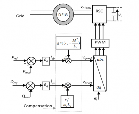
In the decoupled system, Ps, Qs, can be controlled by udr, uqr respectively with Rp and Rq blocks, shown in Figure 3.
Figure 3. Active and reactive power control system of DFIG
In this work, our objective is to evaluate system performance for the following types of controller: the conventional PI controller, fuzzy logic and self-tuning PI fuzzy controller.
2.3 Fuzzy logic controllers (FLC)
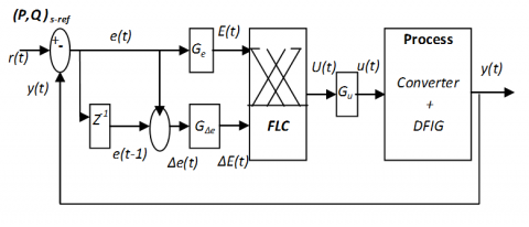
PID controller is a standard control structure for classical control theory. But the performance is greatly distorted and the efficiency is reduced due to nonlinearity in the process plant [30]. The fuzzy control is an intelligence control system to control complex system based on analogizing human ways of fuzzy thinking, which applies fuzzy sets, fuzzy linguistic variables and fuzzy logic inference knowledge. Fuzzy control with the advantage of good performances, robustness and so on need not require know mathematical model of object beforehand, On the other hand, fuzzy control provides a formal methodology for representing, manipulating, and implementing a human’s heuristic knowledge about how to control a system [31]. In the FLC, The reference value r(t) is compared with the actual value y(t) to obtain the error e(t) as shown in Figure 4. Also this error is compared with the previous error e(t-1) to get the change in error $\Delta e(t)$.
Figure 4. Block diagram of FLC controller
There are two inputs for the fuzzy controller. The first input is the error E(t), the second input is the difference between successive errors ΔE(t) and is given by equation (6):
$\begin{align} & E(t)={{G}_{e}}\,[r(t)-y(t)] \\ & \Delta E(t)={{G}_{\Delta e}}\,[e(t)-e(t-1)] \\ \end{align}$ (6)
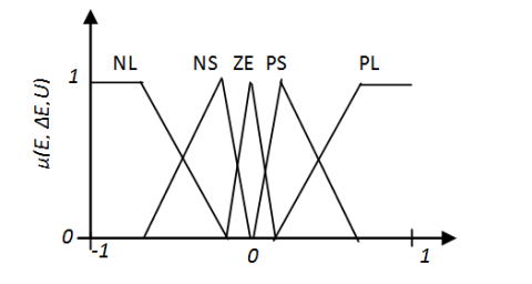
The output is the incremental change of the control signal U(t).U(t) is multiplied by the scale factor Gu to get the output signal u(t). In the system presented in this study, Mamdani type of FLC is used to produce the desired rotor reference voltages. Two independent FLCs are used to control active and reactive powers (Ps,Qs) in the stator of the DFIG. The fuzzy controller is composed of a fuzzifier, a rule inference, a rule base and a defuzzifier. The fuzzifier translates the error and change of error inputs from the real domain into a fuzzy domain. The rule base explains the knowledge to control the system. defuzzification is a mapping from a space of FLC actions defined over an output universe of discourse into a space of non fuzzy control actions. The 5 membership functions of error, variation of error and FLC output are shown in Figure 5.
Figure 5. Membership functions for error, change of error and FLC output
The fuzzy sets have been defined as: NL, negative large; NS, negative small; ZE, zero; PS, positive small; and PL, positive large respectively.
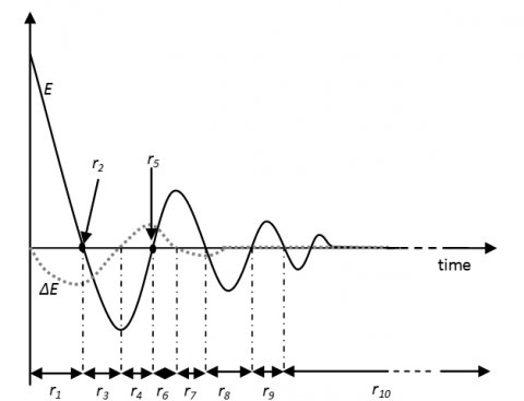
The typical behavior of a controlled system is shown in Figure 5. The response process can be divided into several regions (r1, r2.....r10) by the peak value times. The typical behavior of a controlled system is shown in Figure 6.
For optimum control performance, control rules, membership functions and scaling factors are needed to be tuned properly. This is the fundamental problem in FLC design [32-33]. To overcome the difficulties in optimal control tuning, a standard phase plane technique has been used for designing robust rule base for PI-like fuzzy type control [34- 35].
The signs of ΔU in the regions described in Figure 6 are listed in Table 1, which can be summarized as follows [36]: IF E is zero then ΔU takes the sign of ΔE, else ΔU takes the sign of E.
Figure 6. Operating regions of the time responses of error and change of error
Table 1. The signs of output (ΔU) in the FLC
|
|
r1 |
r2 |
r3 |
r4 |
r5 |
r6 |
r7 |
r8 |
r9 |
r10 |
|
E |
+ |
0 |
- |
- |
0 |
+ |
+ |
- |
+ |
0 |
|
ΔE |
- |
- |
- |
+ |
+ |
+ |
- |
0 |
0 |
0 |
|
ΔU |
+ |
- |
- |
- |
+ |
+ |
+ |
- |
+ |
0 |
Table 2. Fuzzy rules for 5 membership function
|
E ΔE |
NL |
NS |
ZE |
PS |
PL |
|
NL |
NL |
NL |
NS |
NS |
ZE |
|
NS |
NL |
NS |
NS |
ZE |
PS |
|
ZE |
NS |
NS |
ZE |
PS |
PS |
|
PS |
NS |
ZE |
PS |
PS |
PL |
|
PL |
ZE |
PS |
PS |
PL |
PL |
2.4 Self-tuning PI fuzzy controllers
With its advantages of simple structure, good stability, good robustness, reliability, convenient adjustment, PID control has become one of the main industrial control technologies. However, it has some limitations: when the control object is disturbed, the parameters of the controller cannot change automatically to adjust to the change of external environment [37]. The PI controller combined with fuzzy-logic is considered to be an effective solving technique to control the uncertain and nonlinear process.
In order to adjust the parameters of a PI controller, the conventional PI controller is combined with a FLC. Self-tuning PI fuzzy control provides a fuzzy logic supervised PI control scheme in which parameters of a PI controller are updated online as a function of the error and a variation of error, improving the behavior of a classical fixed PI controller. It combines the advantages of a FLC and a conventional PI controller, a self-tuning PI fuzzy control system structure is given in this paper, shown as Figure 7.
Figure 7. Structure of a self-tuning PI fuzzy control
The objective of the FLC is to predict the value of kp and ki at any point of time from the systems response.
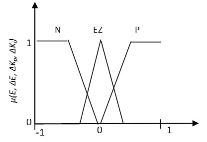
The membership function for E, ΔE, Δkp and Δki are expressed by triangle curve, as shown in Fig. 8. They are defined in the interval [-1, 1].
The fuzzy sets have been defined as: N, negative; ZE, zero; P, positive. The output of the FLC is the incremental change in the kp and ki parameters and the control signal is obtained by the following roles.
The role of proportional coefficient kp is to accelerate the response speed of system, improve regulation accuracy of system. kp bigger system response fester, the regulation accuracy higher, but easy to overshoot; kp value is too small, will reduce accuracy and slow response speed. The role of integral coefficient ki is to eliminate steady-state error. ki large, the steady state error of the system eliminate faster, but ki is too large, in the early stages of response process will produce integral saturation phenomenon, which led to a large overshoot in response process; if ki is too small, will make the stable error of system difficult to eliminate[38].
Figure 8. Membership function scheme of inputs and outputs of FLC
We can calculate output control u using self tuning PI parameters kp, ki, on line, according to discrete differential formula of PI control algorithm. The control signal is obtained by equations (7 and 8):
$\begin{align} & u(t)={{k}_{p}}\,E(t)+{{k}_{i\,}}\int_{0}^{t}{E(\tau )d\tau \,\,} \\ & \,\,\,\,\,\,\,\,\,=[{{k}_{p0}}E(t)\,+{{k}_{i0\,}}\int_{0}^{t}{E(\tau )d\tau ]} \\ & \,\,\,\,\,\,\,\,\,\,\,\,+[{{G}_{p}}\,\Delta {{k}_{p}}(E,\Delta E)\,E(t)+{{G}_{i}}\,\Delta {{k}_{i\,}}(E,\Delta E)\int_{0}^{t}{E(\tau )d\tau ]} \\ & \,\,\,\,\,\,\,\,\,=u(t)\,+\Delta u(t)(E,\Delta E) \\ \end{align}$ (7)
The PI parameters after adjusted are:
$\begin{align} & {{k}_{p}}={{k}_{p0}}\,+{{G}_{p\,}}\Delta {{k}_{p}}(E,\Delta E) \\ & {{k}_{i}}={{k}_{i0}}\,+{{G}_{i\,}}\Delta {{k}_{i}}(E,\Delta E) \\ \end{align}$ (8)
where, Δki and Δki are calibration proportional and integral PI controller gains, whose elements are fuzzy values, these parameters can be updated on-line, according to the process; kp0 and ki0 are initial parameter values of PI controller obtained by a Ziegler-Nichols method.
We can calculate the incremental change in the Δki and Δki parameters according to different error and variation of error (E, ΔE), the corresponding fuzzy rule is shown in Table 3.
Table 3. Δkp and Δki fuzzy control rules
|
E ΔE |
N |
EZ |
P |
|||
|
ΔKp |
ΔKi |
ΔKp |
ΔKi |
ΔKp |
ΔKi |
|
|
N |
N |
P |
P |
N |
N |
P |
|
EZ |
P |
N |
EZ |
EZ |
N |
P |
|
P |
P |
N |
N |
P |
P |
N |
For testing the performance and the efficiency of control strategies proposed in this paper, PI, fuzzy logic and fuzzy self-tuning PI controllers, these controller have been implemented using Matlab and their behaviour has been examined with simulations. The simulated system comprises a 1.5 MW DFIG connected to the 690V, 50Hz grid. The main aim of these controllers is to regulate the active and reactive power in the DFIG at variable wind speed.
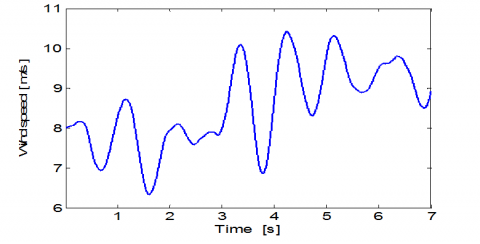
The wind speed varies as shown in Figure 9. When the wind speed is less than rated speed, the system is controlled to track its maximum power operating point.
Figure 9. Wind speed
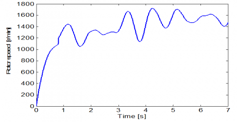
Figure 10. Rotor speed in generator
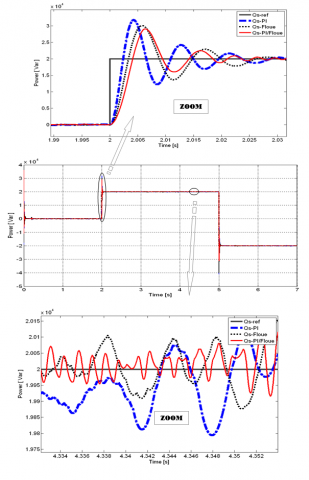
Figure 11. Response of active power and its zoom with three controls methods
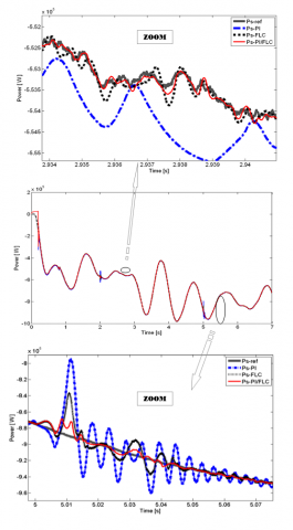
The rotor speed and the stator active power response change corresponding to the wind speed variations, shown in Figure 10 and Figure 11, respectively. Also, the reactive power response in stator of DFIG is shown in Figure 12.
Firstly, the result of simulation shows that the decoupling between the active and reactive power is maintained. Moreover, the effect of coupling between the reactive and active power can be observed, some oscillations which can be seen especially in the active power (at t = 2 s and at t = 5 s) shown in Figure 10. These oscillations appear apparently on the stator active power if an important change is made on the reactive power. Also, it can be seen from Figure 10, the dynamic response of active power has a higher error in the case where the PI controller is used for control the system, the error between the active power and its reference appears with an important and sudden variation of the wind speed. This error decreases with the two other types of controllers.
These results show the robustness of the proposed intelligent controllers compared with PI controller. On the other hand, it can be observed from Figure 10 and Figure 11 which represented the active and reactive powers, by the fuzzy and Fuzzy self tuned based PI controllers the system can reach the set point with a large rise time and more steady state error as compared to the conventional controller. From the results, it is clear that, the self-tuning PI fuzzy logic controller is more effective than fuzzy logic and PI controllers (shorter settling time and small steady-state error).
Figure 12. Response of reactive power and its zoom with three controls methods
The aim of this work is to compare the static and dynamic performances of three types of controllers respectively: (classical PI controller, fuzzy logic and fuzzy self-tuning PI controller). Vector-control is used to independently control the flow of active and reactive power between the stator of the DFIG and the grid. The modeling, the control and the simulation of an electromechanical conversion system based on the DFIG connected directly to the grid by the stator is presented. The comparison between these different control strategies was made with simulations. Simulation results on a DFIG system are provided to demonstrate the effectiveness of the proposed control strategies during variations of active and reactive power; so these results have been done under random wind fluctuations and variations of reactive power. The results indicates that the proposed intelligent controllers based on fuzzy logic show better robustness and have high control precision, compared with PI controller. Also, these results show that the system with conventional PI controller having fixed values of proportional and integral gains, it is not possible to perfectly track the stator active and reactive power references when the wind speed is change. On the other hand, it is concluded that dynamic response characteristics with the PI-type fuzzy logic controller, which adjusts on line the parameters of PI controller, this type has more advantages and the control performance is greatly improved by using this type of control.
[1] Fazelpour, F., Soltani, N., Rosen, M.A. (2015). Wind resource assessment and wind power potential for the city of Ardabil. Iran, International Journal of Energy and Environmental Engineering, 6(4): 431–438. https://doi.org/10.1007/s40095-014-0139-8
[2] Morshed, M.J., Fekih, A. (2017). A new fault ride-through control for DFIG-based wind energy systems. Electric Power Systems Research, 146: 258–269. https://doi.org/10.1016/j.epsr.2017.02.010
[3] Tamaarat, A., Benakcha, A. (2014). Performance of PI controller for control of active and reactive power in DFIG operating in a grid-connected variable speed wind energy conversion system. Front. Energy, 8: 371–378. https://doi.org/10.1007/s11708-014-0318-6
[4] Beddar, A., Bouzekri, H., Babes, B., Afghoul, H. (2016). Experimental enhancement of fuzzy fractional order PI+I controller of grid connected variable speed wind energy conversion system. Energy Conversion and Management, 123: 569–580. https://doi.org/10.1016/j.enconman.2016.06.070
[5] Tang, Y., Xu, L. (1995). A flexible active and reactive power control strategy for a variable speed constant frequency generating system. IEEE Trans. on Power Electronics, 10(4): 472-478. https://doi.org/10.1109/63.391945
[6] Ostadi, A., Yazdani, A., Varma, R.K. (2009). Modeling and Stability Analysis of a DFIG-Based Wind-Power Generator Interfaced with a Series-Compensated Line. IEEE Trans. on Power Delivery, 24(3): 1504-1514. https://doi.org/10.1109/TPWRD.2009.2013667
[7] Kim, J.H., Oh, S.J. (2000). A fuzzy PID controller for nonlinear and uncertain systems. Soft Computing, 4: 123–129. https://doi.org/10.1007/s005000000039
[8] El-Nagar, A.M. (2016). Embedded intelligent adaptive PI controller for an electromechanical system. ISA Transactions, 64: 314–327. https://doi.org/10.1016/j.isatra.2016.06.006
[9] Bouhoune, K., Yazid, K., Boucherit, M.S., Chériti, A. (2017). Hybrid control of the three phase induction machine using artificial neural networks and fuzzy logic. Applied Soft Computing, Elsevier, 55: 289-301. https://doi.org/10.1016/j.asoc.2017.01.048
[10] Ganguly, S., Mahto, T., Mukherjee, V. (2017). Integrated frequency and power control of an isolated hybrid power system considering scaling factor based fuzzy classical controller. Swarm and Evolutionary Computation, Elsevier, 32: 184–201. https://doi.org/10.1016/j.swevo.2016.08.001
[11] Ismail, M., Bendary, A. (2016). Protection of DFIG wind turbine using fuzzy logic control. Alexandria Engineering Journal, 55(2): 941-949. https://doi.org/10.1016/j.aej.2016.02.022
[12] Malhotra, R., Sodhi, R. (2011). Boiler Flow Control Using PID and Fuzzy Logic Controller. IJCSET, 1: 315-319.
[13] Demetgul, M., Ulkir, O., Waqar, T. (2014). Washing machine using fuzzy logic. Automation, Control and Intelligent Systems, 2: 27–32.
[14] Kaler, S., Gupta, R. (2017). Design of Fuzzy Logic controller for Washing Machine with More Features. International Journal of Electronics, Electrical and Computational System, 6: 12-16.
[15] Mohan, B.M., Sinha, A. (2008). Analytical structure and stability analysis of a fuzzy PID controller. Applied Soft Computing, 8(1): 749-758. https://doi.org/10.1016/j.asoc.2007.06.003
[16] Rakhtala, S.M., Shafiee, E.R. (2016). Fuzzy PID control of a stand-alone system based on PEM fuel cell. International Journal of Electrical Power & Energy Systems, 78: 576–590. https://doi.org/10.1016/j.ijepes.2015.12.003
[17] Li, C., Mao, Y., Zhou, J., Zhang, N., An, X. (2017). Design of a fuzzy-PID controller for a nonlinear hydraulic turbine governing system by using a novel gravitational search algorithm based on Cauchy mutation and mass weighting. Applied Soft Computing, 52: 290-305. https://doi.org/10.1016/j.asoc.2016.10.035
[18] Jin, M., Lee, J.Y., Chang, P.H., Kim, M.G., Kang, S.H. (2017). Automatic gain tuning for robust PID control using time-delay control. IFAC-PapersOnLine, 50(1): 4318-4323. https://doi.org/10.1016/j.ifacol.2017.08.856
[19] Baroud, Z., Benmiloud, M., Benalia, A., Ocampo-Martinez, C. (2017). Novel hybrid fuzzy-PID control scheme for air supply in PEM fuel-cell-based systems. International Journal of Hydrogen Energy, 42(15): 10435-10447. https://doi.org/10.1016/j.ijhydene.2017.01.014
[20] Rocha-Osorio, C.M., Solís-Chaves, J.S., Casella, I.R., Capovilla, C.E., Puma, J.A., Sguarezi Filho, A.J. (2017). GPRS/EGPRS standards applied to DTC of a DFIG using fuzzy–PI controllers. International Journal of Electrical Power & Energy Systems, 93: 365-373. https://doi.org/10.1016/j.ijepes.2017.05.033
[21] Giannakis, A., Karlis, A., Karnavas, Y.L. (2018). A combined control strategy of a DFIG based on a sensorless power control through modified phase-locked loop and fuzzy logic controllers. Renewable energy, 121: 489-501. https://doi.org/10.1016/j.renene.2018.01.052
[22] El-Nagar, A.M. (2016). Embedded intelligent adaptive PI controller for an electromechanical system. ISA transactions, 64: 314-327. https://doi.org/10.1016/j.isatra.2016.06.006
[23] Adouni, A., Chariag, D., Diallo, D., Hamed, M.B., Sbita, L. (2016). FDI based on artificial neural network for low-voltage-ride-through in DFIG-based wind turbine. ISA transactions, 64: 353-364. https://doi.org/10.1016/j.isatra.2016.05.009
[24] Tavakoli, A.R., Seifi, A.R., Arefi, M.M. (2018). Designing a self-constructing fuzzy neural network controller for damping power system oscillations. Fuzzy Sets and Systems, 356: 63-76. https://doi.org/10.1016/j.fss.2018.01.006
[25] Tairidis, G., Foutsitzi, G., Koutsianitis, P., Stavroulakis, G.E. (2016). Fine tuning of a fuzzy controller for vibration suppression of smart plates using genetic algorithms. Advances in Engineering Software, 101: 123-135. https://doi.org/10.1016/j.advengsoft.2016.01.019
[26] Öztürk, N., Çelik, E. (2012). Speed control of permanent magnet synchronous motors using fuzzy controller based on genetic algorithms. Electrical Power and Energy Systems. 43(1): 889–898. https://doi.org/10.1016/j.ijepes.2012.06.013
[27] Mahvash, H., Taher, S.A., Rahimi, M., Shahidehpour, M. (2018). DFIG performance improvement in grid connected mode by using fractional order [PI] controller. Electrical Power and Energy Systems, 96: 398–411. https://doi.org/10.1016/j.ijepes.2017.10.008
[28] Abdeddaim, S., Betka, A. (2013). Optimal tracking and robust power control of the DFIG wind turbine. Electrical Power and Energy Systems, 49: 234–242. https://doi.org/10.1016/j.ijepes.2012.12.014
[29] Poitiers, F., Bouaouiche, T., Machmoum, M. (2009). Advanced control of a doubly-fed induction generator for wind energy conversion. Electric Power Systems Research, 79: 1085–1096. https://doi.org/10.1016/j.epsr.2009.01.007
[30] Prasad, P.V.R., Dr.M. Veeraj, S. (2012). Fuzzy Logic Controller Based Analysis of Load Frequency Control of Two Area Inter Connected Power System. International Journal of Emerging Technology and Advanced Engineering, 2(7): 321-327.
[31] Pitalúa-Díaz, N., Herrera-López, E.J., Valencia-Palomo, G. (2015). Comparative Analysis between Conventional PI and Fuzzy Logic PI Controllers for Indoor Benzene Concentrations. Sustainability, 7(5): 5398-5412. https://doi.org/10.3390/su7055398
[32] Li, H., Gatland, H. (1996). Conventional fuzzy control and its enhancements. IEEE Trans. Syst. Man, 26(5): 791–79. https://doi.org/10.1109/3477.537321
[33] Londhe, P.S., Patre, B.M., Tiwari, A.P. (2014). Fuzzy-like PD controller for spatial control of advanced heavy water reactor. Nuclear Engineering and Design, 274: 77-89. https://doi.org/10.1016/j.nucengdes.2014.04.023
[34] Li, H.H. (1995). Gatland, Enhanced methods of fuzzy logic control. Proceedings of the Fourth IEEE International Joint Conference on Fuzzy Systems and The Second International Fuzzy Engineering Symposium, 7: 331–336. https://doi.org/10.1109/FUZZY.1995.409700
[35] Londhe, P.S., Mohan, S., Patre, B.M., Waghmare, L.M. (2017). Robust task-space control of an autonomous underwater vehicle-manipulator system by PID-like fuzzy control scheme with disturbance estimator. Ocean Engineering, 139: 1–13. https://doi.org/10.1016/j.oceaneng.2017.04.030
[36] Srinivasa Rao, T.C., Ponnala, R., Subramanyam, T.C., Srinivas, N. (2013). Frequency Error and Voltage Control by using PI and Fuzzy Logic Controllers for Multi Area Inter Connected Power System. International Journal of Computer Applications, 77(2).
[37] Cheng, H., Zhang, D., Cheng, L. (2013). Comparative Study on Fuzzy PID Controller and Conventional PID Controller. Applied Mechanics and Materials, 328: 112-116. https://doi.org/10.4028/www.scientific.net/AMM.328.112
[38] Wang, R., Dai, Y. (2015). The Anthropomorphic Robot Arm Joint Control Parameter Tuning Based on Ziegler Nichols PID. (ICMEIS 2015). Proceedings of the 3rd International Conference on Mechanical Engineering and Intelligent Systems, Proc. 136-141. https://doi.org/10.2991/icmeis-15.2015.27