Khadar Saad | Kouzou Abdellah
OPEN ACCESS
Today, direct torque control (DTC) is one of the most actively researched control techniques due to its exceptional dynamic response and less dependence on motor parameters. However, the DTC technique has a disadvantage that the stator resistance variation due to inter-turn short circuit (ITSC) fault causes an estimation error of the stator flux, this leads to a decline in the performance of DTC technique. To solve this problem, this paper proposes a DTC technique of open end-winding induction motor (OEW-IM) under ITSC fault with stator resistance compensator based on model reference adaptive system (MRAS). The main objective of the proposed estimation scheme is to improve the DTC performance under fault condition, where the stator resistance value is updated during operation to compensate the fault effects. The control system performance is verified in terms of the healthy and faulty performances through the simulation. Based on the obtained simulation results, it can be said that the effectiveness of the proposed control system is clearly validated.
induction motor, open-end winding, MRAS estimator, stator resistance compensator, direct torque control, inter-turn short circuit fault
During the last years, a dual three-phase inverters feeding OEW-IM have attracted great interest in industry for variable speed applications due to their many advantages compared to the traditional single-sided supply configurations. They have several main advantages such as each inverter works at half of the power because the motor is powered by the both sides of each winding, no need to have the motor’s neutral point, each phase current can be controlled separately [1-2], and the possibility to reduce the common mode voltage [3-4]. However, despite all their previous advantages, they are subjected to electrical or mechanical faults due to various stresses during operating conditions, which can affect their lifespan [2]. These faults can be divided according to the main components of the machine such as disorders of the stator, the rotor and the bearings. An insulation breakdown between turns for the same coil produces a stator winding fault. This kind of fault is called turn to turn or ITSC [4-8]. This fault causes a large circulating fault current in the shorted turns of the stator winding, leading to excessive heat generation in the shorted turns [9]. This further degrades the insulation, and finally results to rapidly progress to more severe faults such as line-to-ground or line-to-line faults [10]. These faults can damage the stator winding, which accelerates motor degradation. The authors in [11] evaluated the faulty performance of induction motor, which showed that the average torque is reduced and the torque ripples is increased under ITSC fault of the same phase. Consequently, an effective and robust control design is needed, in order to extend the motor lifetime, and ensure the continuation of the drive systems at its minimum operating performance at least until the faults are rectified.
This paper deals with an OEW-IM topology instead of the star connection topology, which is connected to dual two-level voltage inverters supplied by one DC source. Firstly, this paper presents a mathematical model by which behavior of OEW-IM with ITSC fault in the same phase can be analyzed. Secondly, a proposed direct torque control technique is used, which offers a good performance, a better reference speed tracking response and robustness under the rotor parameters variation [12-13], but it requires the estimation of the motor parameters to ensure the robustness (particularly, stator resistance) [14], which are used in machine modeling under stator winding fault. Thus, it is important to add an estimation algorithm in order to compensate the variation effects of stator resistance. In addition, the accurate information obtained from the rotor speed is more than necessary to achieve an accurate control and increase the reliability of the system. Consequently, a MRAS for parallel estimation of speed and stator resistance is used in this paper. The used estimator requires only the measurements of the stator voltages and currents. The present paper is structures as follows: In Section 2, a brief review of the dual inverter feeding the studied OEW-IM with ITSC fault in A-phase is presented. Then, a review on the principle of the used DTC technique is explained in section 3. The discussion of the MRAS estimator proposed in this paper to estimate the resistance of stator winding is presented in details in Section 4. The simulation results are drawn and discussed in section 5. Finally, this paper ends with a conclusion in Section 6.
This paper presents an another method of modeling of the IM under ITSC fault. The modeling method is based on the theory of electromagnetic coupling of electrical circuits [2, 6, 8]. In other words, one must rewrite the stator differential equations taking into account the changing parameters such as the matrices of stator resistance, stator inductance and mutual inductance stator-rotor. Here are the following short-circuit coefficients:
Short-circuit coefficient relative to the A-phase (a1-a2): $K_{s a}=\frac{N_{c a}}{N_{s}}$
Short-circuit coefficient relative to the B-phase (b1-b2): $K_{s b}=\frac{N_{c b}}{N_{s}}$
Short-circuit coefficient relative to the C-phase (c1-c2): $K_{s b}=\frac{N_{c b}}{N_{s}}$
It has been shown that the parameters of the motor affected by the short-circuit are directly linked to the three coefficients $r_{s a}, r_{s b}$ and $r_{s c}$ [2, 6, 11]. Consequently, the inductances and resistance matrices will be changed by taking into account the introduced coefficients of short-circuited turns. The matrice of the resistance of the stator windings are defined as follows:
$\left[R_{s f}\right]=R_{s}\left[\begin{array}{ccc}1 & 0 & 0 \\ 0 & 1 & 0 \\ 0 & 0 & 1\end{array}\right]\left[\begin{array}{c}r_{s a} \\ r_{s b} \\ r_{s c}\end{array}\right]$ (1)
The matrice of the stator leakage inductance is given as follows:
$\left[l_{s f}\right]=\left[\begin{array}{ccc}r_{s a}^{2} l_{s} & 0 & 0 \\ 0 & r_{s a}^{2} l_{s} & 0 \\ 0 & 0 & r_{s a}^{2} l_{s}\end{array}\right]$ (2)
The stator inductance is given as follows:
$L_{s}=l_{s}+M_{s s}$ (3)
The matrice of the mutual inductance between stator phases is given as follows:
$\left[M_{s s f}\right]=M_{s s}\left[\begin{array}{ccc}r_{s a}^{2} & -\frac{r_{s a} r_{s b}}{2} & -\frac{r_{s a} r_{s c}}{2} \\ -\frac{r_{s a} r_{s b}}{2} & r_{s b}^{2} & -\frac{r_{s c} r_{s b}}{2} \\ -\frac{r_{s a} r_{s c}}{2} & -\frac{r_{s c} r_{s b}}{2} & r_{s c}^{2}\end{array}\right]$ (4)
The matrice of the mutual inductance between the stator phases and the rotor phases is given as follows with $\left(\alpha=\frac{2 \pi}{3}\right)$:
$\left[M_{s r f}\right]$
$=M_{o}\left[\begin{array}{ccc}r_{s a} \cos \theta & r_{s a} \cos (\theta+\alpha) & r_{s a} \cos (\theta-\alpha) \\ r_{s b} \cos (\theta-\alpha) & r_{s b} \cos \theta & r_{s b} \cos (\theta+\alpha) \\ r_{s c} \cos (\theta+\alpha) & r_{s c} \cos (\theta-\alpha) & r_{s c} \cos \theta\end{array}\right]$ (5)
The matrice of the mutual inductance between the rotor and stator phases is given by:
$\left[M_{r s f}\right]^{T}=\left[M_{s f f}\right]$ (6)
where, $M_{0}$ is the maximum value of the mutual inductance between the stator and rotor phases.
If the number of turns in three phase stator winding are the same, the machine is balanced, so the three coefficients are equal $\left(r_{s a}=r_{s b}=r_{s c}=1\right)$. When the machine is running under ITSC fault in A-phase only, the coefficient corresponding to other phases are constant and equal to unity $r_{s b}=r_{s c}=1$, while $r_{s a}$ is not constant and it remains between 0 and 1 depending on the degree or number of short-circuited turns. The three coefficients in the healthy and faulty mode operation are given as follows:
$r_{s a}=r_{s b}=r_{s c}=1 \Leftrightarrow N_{s}=160, N_{s a}=0$ (7)
$r_{s a}=0.84, r_{s b}=r_{s c}=1 \Leftrightarrow N_{s}=160, N_{s a}=16$ (8)
The global model in three-phase reference frame for the prediction of ITSC in the first coil fault are written as follows [2]:
The three-phase stator currents can be given by:
$\left\{ \begin{align} & \frac{d{{i}_{sa}}}{dt}={{V}_{SA}}+{{K}_{A1}}{{i}_{sa}}+{{K}_{A2}}{{i}_{sb}}+{{K}_{A1}}{{i}_{sc}}+k.{{r}_{sa}}r_{sb}^{2}r_{sc}^{2}\left[ G{{\varphi }_{ra}}+\left( \frac{\sqrt{3}}{2}\omega -\frac{G}{2} \right){{\varphi }_{rb}}-\left( \frac{\sqrt{3}}{2}\omega +\frac{G}{2} \right){{\varphi }_{rc}} \right] \\ & \frac{d{{i}_{sb}}}{dt}={{V}_{SB}}+{{K}_{B1}}{{i}_{sa}}+{{K}_{B2}}{{i}_{sb}}+{{K}_{B1}}{{i}_{sc}}+k.{{r}_{sa}}r_{sb}^{2}r_{sc}^{2}\left[ -\left( \frac{\sqrt{3}}{2}\omega +\frac{G}{2} \right){{\varphi }_{ra}}+G{{\varphi }_{rb}}+\left( \frac{\sqrt{3}}{2}\omega -\frac{G}{2} \right){{\varphi }_{rc}} \right] \\ & \frac{d{{i}_{sc}}}{dt}={{V}_{SC}}+{{K}_{C1}}{{i}_{sa}}+{{K}_{C2}}{{i}_{sb}}+{{K}_{C1}}{{i}_{sc}}+k.{{r}_{sa}}r_{sb}^{2}r_{sc}^{2}\left[ \left( \frac{\sqrt{3}}{2}\omega -\frac{G}{2} \right){{\varphi }_{ra}}-\left( \frac{\sqrt{3}}{2}\omega +\frac{G}{2} \right){{\varphi }_{rb}}+G{{\varphi }_{rc}} \right] \\ \end{align} \right.$ (9)
The three-phase rotor flux can be given by:
$\left\{ \begin{align} & \frac{d{{\varphi }_{ra}}}{dt}=\lambda \left( {{r}_{sa}}{{i}_{sa}}-\frac{{{r}_{sb}}}{2}{{i}_{sb}}-\frac{{{r}_{sc}}}{2}{{i}_{sc}} \right)-\frac{{{R}_{r}}A}{C}{{\varphi }_{ra}}-\left( \frac{{{R}_{r}}B}{C}+\frac{\sqrt{3}}{3}\omega \right){{\varphi }_{rb}}-\left( \frac{{{R}_{r}}B}{C}-\frac{\sqrt{3}}{3}\omega \right){{\varphi }_{rc}} \\ & \frac{d{{\varphi }_{rb}}}{dt}=\lambda \left( -\frac{{{r}_{sa}}}{2}{{i}_{sa}}+{{r}_{sb}}{{i}_{sb}}-\frac{{{r}_{sc}}}{2}{{i}_{sc}} \right)-\left( \frac{{{R}_{r}}B}{C}-\frac{\sqrt{3}}{3}\omega \right){{\varphi }_{ra}}-\frac{{{R}_{r}}A}{C}{{\varphi }_{rb}}-\left( \frac{{{R}_{r}}B}{C}+\frac{\sqrt{3}}{3}\omega \right){{\varphi }_{rc}} \\ & \frac{d{{\varphi }_{rc}}}{dt}=\lambda \left( -\frac{{{r}_{sa}}}{2}{{i}_{sa}}-\frac{{{r}_{sb}}}{2}{{i}_{sb}}+{{r}_{sc}}{{i}_{sc}} \right)-\left( \frac{{{R}_{r}}B}{C}+\frac{\sqrt{3}}{3}\omega \right){{\varphi }_{ra}}-\left( \frac{{{R}_{r}}B}{C}-\frac{\sqrt{3}}{3}\omega \right){{\varphi }_{rb}}-\frac{{{R}_{r}}A}{C}{{\varphi }_{rc}} \\ \end{align} \right.$ (10)
The electromagnetic torque can be found using the stator current and rotor flux as follows:
$T_{e}=\frac{n_{p} M_{s r}}{L_{r}}\left[\left(i_{s b} \varphi_{r c}-i_{s c} \varphi_{r b}\right)-\left(i_{s a} \varphi_{r c}-i_{s c} \varphi_{r a}\right)+\left(i_{s a} \varphi_{r a}-i_{s b} \varphi_{r b}\right)\right]$ (11)
where, $R_{s f}, l_{s f}, M_{s s f}$ and $M_{s r f}$ are the parameter values in faulty state.
Figure $1,$ illustrates the circuit principle of the studied topology in this paper $[2,4,15],$ where only one DC source is used to the dual inverter feeding the open-end stator winding of the induction motor. The two inverters are identified by indices 1 and 2, while the inverter 1 is connected to stator winding terminal of $a_{1},$ winding stator to connected is 2 inverter and $c_{1}, b_{1}$ terminal of $a_{2}, b_{2}$ and $c_{1} .$ By using this structure, the inverter can be operated as a two-level or threelevel, depending on the ratio of DC-link voltages, without the need to change the structure of the inverter [2].
Figure 1. Open-end winding three-phase induction motor
The DTC is based on the direct determination of the sequence control used to control inverter switches to select the proper voltage vectors feeding the open-end winding-IM [16-20]. The DTC strategy scheme consists of the estimation block for the torque and flux, two hysteresis controllers and two switching table [4]. It is much simpler than the vector control scheme due to the absence of coordinate transformation and a position encoder [12-14]. In fact, in order to apply DTC technique to this studied configuration, we define two switching tables, where the first is used to control the inverter 1 and the second to control the inverter 2. The measured stator currents in α-β frame can be expressed using Clarke transformation as follows [4]:
$\left\{\begin{array}{l}i_{s \alpha}=\sqrt{\frac{2}{3}}\left(i_{s a 1}-i_{s a 2}\right) \\ i_{s \beta}=\frac{1}{\sqrt{2}}\left(\left(i_{s b 1}-i_{s b 2}\right)-\left(i_{s c 1}-i_{s c 2}\right)\right)\end{array}\right.$ (12)
The equations of stator phase voltage in the α-β can be expressed as:
$\left\{V_{s \alpha \beta}=V_{s \alpha 1 \beta 1}-V_{s \alpha 2 \beta 2}\right.$ (13)
$\left\{\begin{array}{l}V_{s \alpha 1 \beta 1}=\frac{2}{3} V_{d c}\left(S_{a 1}+S_{b 1} e^{j \frac{2 \pi}{3}}+S_{c 1} \cdot e^{j \frac{4 \pi}{3}}\right) \\ V_{s \alpha 2 \beta 2}=\frac{2}{3} V_{d c}\left(S_{a 2}+S_{b 2} e^{j \frac{2 \pi}{3}}+S_{c 2} e^{j \frac{4 \pi}{3}}\right)\end{array}\right.$ (14)
With $: S_{a 1}, \quad S_{b 1}, \quad S_{c 1}$ and $S_{a 2}, S_{b 2}, S_{c 2}$ are the logical variables representing the switches state of inverter 1 and inverter 2, respectively.
3.1 The flux and torque estimation
The stator flux vector is estimated by integrating the difference between the input stator voltage and the voltage drop across the stator resistance as follows:
$\left\{\begin{array}{l}\hat{\varphi}_{s \alpha}=\int V_{s \alpha}-R_{s} i_{s \alpha} \\ \hat{\varphi}_{s \beta}=\int V_{s \beta}-R_{s} i_{s \beta}\end{array}\right.$ (15)
The magnitude and angle of the stator flux vector in α-β frame are estimated by the following expression:
$\phi_{s}=\sqrt{\varphi_{s \alpha}^{2}+\varphi_{s \beta}^{2}}$ (16)
$\theta_{s}=\tan ^{-1} \frac{\hat{\varphi}_{s \alpha}}{\hat{\varphi}_{s \beta}}$ (17)
The electromagnetic torque can be estimated by:
$\hat{T}_{e}=n_{p}\left(\varphi_{s_{a}} i_{s \beta}-\varphi_{s \beta} i_{s \alpha}\right)$ (18)
3.2 The flux and torque regulation
The reference stator flux is compared with their estimated value and the flux errors are processed through a two levels hysteresis comparator. The flux hysteresis controller conditions can be defined by the following equations:
$d \varphi_{s}=1$ for $\left|\varphi_{s}\right| \leq\left|\varphi_{s e f}\right|-\left|\Delta \varphi_{s}\right|$ (19)
$d \varphi_{s}=0$ for $\left|\varphi_{s}\right| \geq\left|\varphi_{s r e f}\right|+\left|\Delta \varphi_{s}\right|$ (20)
Then, the torque magnitude is compared with its estimated value and the torque errors are processed through a three levels hysteresis comparator. The torque hysteresis controller conditions can be defined by the following equations:
$d T_{e}=1$ for $\left|T_{e}\right| \leq\left|T_{r e f}\right|-\left|\Delta T_{e}\right|$ (21)
$d T_{e}=0$ for $\left|T_{\text {ref }}\right|-\left|\Delta T_{e}\right| \leq\left|T_{e}\right| \leq\left|T_{\text {ref }}\right|+\left|\Delta T_{e}\right|$ (22)
$d T_{e}=-1$ for $\left|T_{e}\right| \geq\left|T_{r e f}\right|+\left|\Delta T_{e}\right|$ (23)
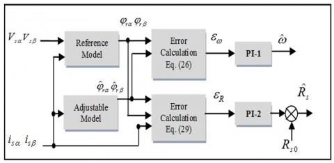
Sensor-less control strategies are becoming more and more important as they can eliminate the mechanical sensor in order to decrease system’s cost and to improve its reliability [21-23], Model Reference Adaptive System (MRAS) is applied in this study to simultaneously estimate the rotor flux, rotor speed and stator resistance using the measurement of the stator currents and stator voltages in the α-β frame [21]. Figure 2 shows the block diagram of MRAS technique containing two models and two PI controllers. The first (reference model) is derived by integrating the stator voltage equation of the three-phase induction motor that determines the rotor flux components in the α-β frame, which is independent of rotor speed. The second (adjustable model) is based on the current model that determines the estimated values of the rotor flux components, which is using rotor speed as a parameter. The two models are obtained in the α-β frame as follows [21-23]:
a-Reference model
$\left\{\begin{array}{l}\frac{d \varphi_{r \alpha}}{d t}=\frac{L_{r}}{M_{s r}}\left[V_{s \alpha}-R_{s} i_{s \alpha}-\sigma L_{s} \frac{d i_{s \alpha}}{d t}\right] \\ \frac{d \varphi_{r \beta}}{d t}=\frac{L_{r}}{M_{s r}}\left[V_{s \beta}-R_{s} i_{s \beta}-\sigma L_{s} \frac{d i_{s \beta}}{d t}\right]\end{array}\right.$ (24)
b-Adjustable model
$\left\{\begin{array}{l}\frac{d \hat{\varphi}_{r \alpha}}{d t}=\frac{R_{r} M_{s r}}{L_{r}} i_{s \alpha}-\frac{R_{r}}{L_{r}} \varphi_{r \alpha}+\omega \cdot \varphi_{r \alpha} \\ \frac{d \hat{\varphi}_{r \beta}}{d t}=\frac{R_{r} M_{s r}}{L_{r}} i_{s \beta}-\frac{R_{r}}{L_{r}} \phi_{r \beta}+\omega \cdot \varphi_{r \beta}\end{array}\right.$ (25)
The error signal between the two models can be obtained by:
$\varepsilon_{\varphi}=\varphi_{r \alpha} \varphi_{r \beta}-\varphi_{r \alpha} \varphi_{r \beta}$ (26)
The $\mathcal{E}_{\varphi}$ signal is fed into a PI-1 controller whose output is the estimated value of the rotor speed as [21-23]:
$\omega=k_{P_{o}} \cdot\left(\varphi_{r \alpha} \varphi_{r \beta}-\varphi_{r \alpha} \varphi_{r \beta}\right)+k_{I \omega} \int\left(\varphi_{r \alpha} \varphi_{r \beta}-\varphi_{r \alpha} \varphi_{r \beta}\right) d t$ (27)
where, $k_{I w}$ and $k_{P w}$ are the proportional and the integral parameters of the PI-2 controller used in the speed estimation respectively.
The PI-2 controller produces the estimated stator resistance value basing on the error signals between the reference (24) and estimated rotor flux given by (25) with the measured stator currents as follows [21]:
$\hat{R}_{s}=R_{s 0}+k_{P R} \cdot \mathcal{E}_{R}+k_{I R} \int \varepsilon_{R} \cdot d t$ (28)
with:
$\varepsilon_{R}=i_{s \alpha}\left(\varphi_{r \alpha}-\varphi_{r \alpha}\right)+i_{s \beta}\left(\varphi_{r \beta}-\varphi_{r \beta}\right)$ (29)
where, $R_{S 0}$ is the nominal stator resistance, $k_{P R}$ and ${k}_{I R}$ are the proportional and the integral parameters of the PI-2 controller used in the stator resistance compensator respectively.
Figure 2. Block diagram of stator resistance compensator based on MRAS technique
In this section, computer simulations have been carried out to validate the effectiveness of the proposed sensorless DTC using MRAS with and without the $R_{s}$ compensator for OEW-IM fed by a two-level inverter, as shown in Figure 3. The control scheme allows eliminating the speed sensor, where the rotor speed signal is replaced by the estimated one. Consequently, a MRAS for parallel estimation of rotor speed and stator resistance is used in this paper. Matlab/Simulink environment has been used for the purpose to testing the machine performance under the short-circuit fault which touch 10% of the turns of the first phase (A), that is to say 16 turns of the first coils are short circuited. It is important to mention that during the simulation test the stator flux reference was set to 1.2Wb and a step reference speed of 50 rad/sec is applied with the machine mechanically unloaded, then it is loaded with its load torque of 2 Nm at 1.5 sec.
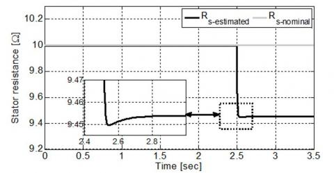
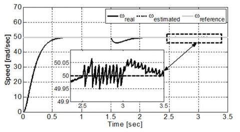
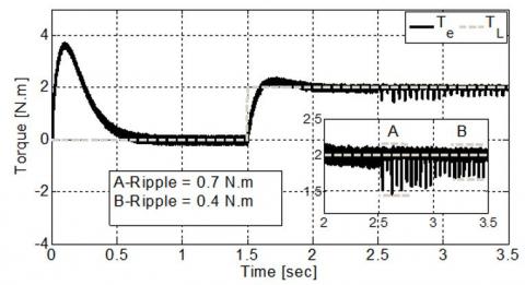
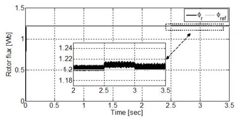
Figure 4 shows the stator estimated resistance of the studied motor. When the ITSC fault is applied at t = 2.5sec, it can be seen that the proposed estimator tracks the change in the stator real resistance very well with negligible error, where the estimated $R_{s}$ converges to the value of 9.455 Ω. Figure 5 shows the response of real, estimated and reference speeds, it can be observed that the motor speed and estimated speed is able to track the desired reference speed with a very fast response and without overshoot, and then the ITSC fault is occurred at t=2.5 sec without the $R_{s}$ compensator, it can be observed that the real and estimated speed values increases slightly and oscillates around the 50.05 rad/sec. The appearance of these oscillations is directly related to the existence of a residual asymmetry in the motor stator circuit. After 0.5 second. The speed ripples are decreased, when the proposed $R_{s}$ estimation is activated, confirming the effectiveness of the MRAS technique. Furthermore, the real speed is compared with the estimated one, as illustrated in Figure 6, which presents the speed estimation error. Where, this error is nearly equal to 0.09 rad/sec during the transient state. It is obvious that this estimation error rejoins approximately the zero when the steady state of the motor is attained. While the Figure 7 shows the electromagnetic torque and the load torque, before and after the fault appearance without and with the $R_{s}$ compensator. The electromagnetic torque presents fast dynamic and it is equal to the load torque in steady state. When the 10% short circuit fault occurs at 2.5 sec without the $R_{s}$ compensator, the torque fluctuation is 0.7 N.m. In fact, these cause fluctuations of the rotor speed, which generates acoustic noise and thus, an abnormal operation of the motor. When the $R_{s}$ estimation is activated at t = 3sec, the torque fluctuations is relatively low about 0.4 N.m. Figure 8 presents the response of the stator flux amplitude. It can be observed that the ITSC fault of the same coil introduced some small fluctuations in the rotor flux. As soon as the $R_{s}$ estimation is enabled, the rotor flux converges toward the reference value (1.2Wb) with fluctuations slightly.
Figure 3. Block diagram of DTC strategy with stator resistance compensator based on MRAS technique
Figure 4. The stator resistance variation
Figure 5. The real, estimated and reference speed
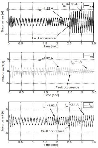
The three phase stator currents of the studied OEW-IM are shown in Figure 9. Before the occurrence of the winding stator faults, both of these currents are balanced. However, with fault occurrence at t=2.5 sec, it is clear that the A-phase current grows (${i}_{s a}$=4.05A) compared to the healthy regime. This increase is obviously the simultaneous decrease of resistance and the inductances. Also, the C-phase current amplitude (${i}_{s c}$) is enlarged, whose amplitude is bigger than B-phase currents (${i}_{s b}$) making the DTC strategy perform poorly. In order to avoid this, the $R_s $estimation has been applied at t= 3 sec. it is observed that the proposed compensator scheme improves the stator currents behavior.
Figure 6. The speed estimation error
Figure 7. The electromagnetic torque and the load torque
Figure 8. The stator flux amplitude
According to the obtained results, it can be seen that the transition from the pre-fault to the post-fault situation is almost unnoticeable. So, the sensorless DTC strategy based on MRAS with $R_s$ compensator is effective during the loss of one phase.
Figure 9. The three phase stator currents
This paper proposes a sensorless DTC strategy based on the stator resistance compensator for the control of OEW-IM topology, where the MRAS concept is used for the estimation of the stator resistance and the rotor speed. The main purpose of stator resistance estimation is to compensate for inter-turn short circuit fault in stator winding. The compensator scheme, working in parallel with the MRAS, allows obtaining the correct value of stator resistance, which can change from the nominal ones according to ITSC fault. Based on the obtained results, it can be said that the proposed control possesses a great tracking capability at both healthy and faulty mode operation, confirming the effectiveness of the proposed compensator scheme.
The parameters of the motor used for modeling studies are listed as follows:
$n_{p}=2:$ Number of pole pairs, $R_{s}=6.3 \Omega:$ Stator resistance, $L_{s}=0.4642 \mathrm{H}:$ Stator inductance, $M_{s r}=0.4212 \mathrm{H}:$ Mutual inducta stator-rotor, $R_{r}=6.3 \Omega$ : Rotor resistance, $L_{r}=0.4246 \mathrm{H}$ : Rotor inductance, $\mathrm{J}=0.02 \mathrm{Kg} / \mathrm{m}^{2}:$ Moment of inertia.
$\left\{\begin{array}{l}A=\left(M_{r r}+l_{r}\right)^{2}-\frac{M_{r r}^{2}}{4}, B=\frac{M_{r r} l_{r}}{2}+\frac{3 M_{r r}^{2}}{4}, \\ C=l_{r}^{3}+3 l_{r}^{2} M_{r r}+\frac{9 M_{r r}^{2} l_{r}}{4}, \\ G=\frac{R_{r}(A-B)}{C} L_{r}=\left(M_{r r}+l_{r}\right) \\ d_{1}=\left(z+l_{r}\right)^{2}-\frac{z^{2}}{4}, d_{2}=\frac{z\left(z+l_{r}\right)}{2}+\frac{z^{2}}{4} ,\\ z=M_{s r}-\frac{3 M_{r r}^{2}(A-B)}{2 C}, \lambda=\frac{M_{S R} R_{r}(A-B)}{C}, \omega=n_{p} \Omega\end{array}\right.$
DTC: Direct Torque Control
MRAS: Model Reference Adaptive System
ITSC: Inter-Turn Short Circuit
OEW-IM: Open End Winding Induction Motor.
$R_s$: Stator resistance (Ω).
$L_s$: Stator inductance (H).
$M_{s s}$: Mutual inductance between stator phases (H).
$M_{s r}$: Mutual inductance between stator-rotor (H).
$R_r$: Rotor resistance (Ω).
$L_r$: Rotor inductance (H).
$M_{r r}$: Mutual inductance between rotor phases (H).
$M_{r s}$: Mutual inductance between rotor-stator (H).
$l_s$: Leakage inductance of stator (H).
$l_r$: Leakage inductance of rotor (H).
[1] Riedemann, J., Clare, J.C., Wheeler, P.W., Gimenez, R.B., Rivera, M., Peña, R. (2016). Open-end winding induction machine fed by a dual-output indirect matrix converter. IEEE Transactions on Industrial Electronics, 63(7): 4118-4128. https://doi.org/10.1109/TIE.2016.2531020
[2] Khadar, S., Kouzou, A. (2018). Implementation of control strategy based on SVM for open-end winding induction motor with short circuit fault between turns in stator windings. Journal of Automation & Systems Engineering, 12(3): 12-25.
[3] Rodriguez, J., Silva, E., Blaabjerg, F., Wheeler, P., Clare, J., Pontt, J. (2005). Matrix converter controlled with the direct transfer function approach: Analysis. Modelling and simulation in International journal of electronics, 92(2): 63-85. https://doi.org/10.1080/00207210512331337686
[4] Khadar, S., Kouzou, A., Hafaifa, A. (2018). Sensor-less direct torque control of induction motor with an open-end stator winding using an adaptive luenberger observer. In 2018 15th International Multi-Conference on Systems, Signals & Devices (SSD), Hammamet, Tunisia, pp. 19-22. https://doi.org/10.1109/SSD.2018.8570691
[5] Bouzid, M.B.K., Champenois, G., Bellaaj, N.M., Signac, L., Jelassi, K. (2008). An effective neural approach for the automatic location of stator interturn faults in induction motor. IEEE Transactions on Industrial Electronics, 55(12): 4277-4289. https://doi.org/10.1109/TIE.2008.2004667
[6] Khadar, S., Kouzou, A., Rezzaoui, M.M., Hafaifa, A. (2020). Sensorless control technique of open-end winding five phase induction motor under partial stator winding short-circuit. Periodica Polytechnica Electrical Engineering and Computer Science, 64(1): 2-19. https://doi.org/10.3311/PPee.14306
[7] Thomson, W.T., Fenger, M. (2001). Current Signature Analysis to detect Induction motor faults. IEEE industry Applications Magazine, 7(4): 26-34. https://doi.org/10.1109/2943.930988
[8] Khadar, S., Kouzou, A. (2018). A new modeling method for turn to turn fault in same phase of five phase induction motor with open-end stator winding. Second International Conference on Electrical Engineering ICEEB’2018. Biskra, Algeria.
[9] Abdesselam, L., Ammar, M., Guy, C. (2011). Analysis of inter-turn short circuit in slots by finite element model. In 2011 10th International Conference on Environment and Electrical Engineering, Rome, Italy, pp. 1-4. https://doi.org/10.1109/EEEIC.2011.5874589
[10] Bechkaoui, A., Ameur, A., Bouras, S., Ouamrane, K. (2014). Diagnosis of turn short circuit fault in PMSM sliding-mode control based on adaptive fuzzy logic-2 speed controller. Advances in Modelling and Analysis C, 70(1): 29-45.
[11] Khodja, D.E., Aissa, K. (2009). Three-phases model of the induction machine taking account the stator faults. International Journal of Mechanical and Mechatronics Engineering, 3(4): 363-366.
[12] Khadar, S., Kouzou, A. (2017). Switching table for direct torque controlled PMSM fed by Three-Level NPC inverter to minimize flux ripple. The 3rd International Conference on Power Electronics and their Applications (ICPEA), Djelfa, Algeria, pp. 16-17.
[13] Khadar, S., Kouzou, A. (2018). Dual direct torque control of doubly fed induction machine using Artificial neural. The 3rd International Conference on Pattern Analysis and Intelligent Systems, Oct. 24-2, Tebessa, Algeria. https://doi.org/10.1109/PAIS.2018.8598497
[14] Khadar, S., Kouzou, A., Benguesmia, H. (2018). Fuzzy stator resistance estimator of induction motor fed by a three levels NPC inverter controlled by direct torque control. The International Conference on Applied Smart Systems (ICASS'18), 24 to 25 Nov 2018, Medea, Algeria. https://doi.org/10.1109/ICASS.2018.8651999
[15] Srinath, V., Mohan, M., Chaturvedi, D.K. (2017). A multilevel inverter system for an induction motor with open-ended windings. International Journal of Computer Applications, 163(10): 6-13. https://doi.org/10.5120/ijca2017913528
[16] Rashag, H.F., Koh, S.P., Abdalla, A.N., Tan, N.M.L., Chong, K.H. (2013). Modified direct torque control using algorithm control of stator flux estimation and space vector modulation based on fuzzy logic control for achieving high performance from induction motors. Journal of Power Electronics, 13(3): 369-379. https://doi.org/10.6113/JPE.2013.13.3.369
[17] Khadar, S., Kouzou, A. (2018). Analyse et modélisation des défauts d'une MAS dans sa partie statorique commandé par DTC. International Symposium on Mechatronics & Renewable Energies ISMRE’2018, El-Oued, Algeria. http://dspace.univ-eloued.dz/handle/123456789/1407
[18] Ghanbari, D., Abjadi, N.R., Ghanbari, A. (2014). Direct torque and flux control of five-phase induction motor using fuzzy logic. International Journal of Innovative Research in Electrical, Electronics, Instrumentation and Control Engineering, 2(12): 2196-2202.
[19] Fouad, B., Ali, C., Samir, Z., Salah, S. (2017). Direct torque control of induction motor fed by three-level inverter using fuzzy logic. Advances in Modelling and Analysis C, 72(4): 248-265.
[20] Hellali, L., Belhamdi, S., Loutfi, B., Hassen, R. (2018). Direct torque control of doubly star induction machine fed by voltage source inverter using type-2 fuzzy logic speed controller. Advances in Modelling and Analysis C, 73(4): 202-207.
[21] Khadar, S., Kouzou, A., Hafaifa, A., Iqbal, A. (2019). Investigation on SVM-Backstepping sensorless control of five-phase open-end winding induction motor based on model reference adaptive system and parameter estimation. Engineering Science and Technology, an International Journal, 22(4): 1013-1026. https://doi.org/10.1016/j.jestch.2019.02.008
[22] Dehghan-Azad, E., Gadoue, S., Atkinson, D., Slater, H., Barrass, P., Blaabjerg, F. (2018). Sensorless control of IM based on stator-voltage MRAS for limp-home EV applications. IEEE Transactions on Power Electronics, 33(3): 1911-1921. https://doi.org/10.1109/TPEL.2017.2695259
[23] Mohamed, M., Ahmed, A., Hassan, M. (2015). MRAS-based sensorless speed backstepping control for induction machine, using a flux sliding mode observer. Turkish Journal of Electrical Engineering & Computer Sciences, 23(1): 187-200.