Benyettou Loutfi
OPEN ACCESS
This paper presents shunt active power filter based on fuzzy logic controller is modeled, simulated, and tested. The fundament of Instantaneous Reactive Power Algorithm is used for extracting compensated reference harmonic current. A fuzzy logic controlled shunt Active Power Filter Using Hysteresis Band Current is applied to regulate the DC capacitor voltage of shunt Active Power Filter in order to improve the active filter dynamic, to ensure sinusoidal source currents and to produce a high power quality. The main goal of the proposed active filtering system is to maintain the THD well within IEEE on harmonics levels. Simulation results through MATLAB/Simulink are presented and interpreted. It is demonstrated that the fuzzy logic controller improves the performance of the active power filter.
shunt active power filter (SAPF), hysteresis controller, fuzzy logic, THD.
The evolution of the power electronics components has promoted the expansion of the converters market. This evolution has brought great flexibility especially in the control of electrical machines. But they have important effects [1]:
These converters absorb non-sinusoidal currents, so they behave like a generator of currents harmonics. If the fundamental of the current is not in phase with the voltage, we have consumption of reactive power; the power consumed is greater than the actual active power. Harmonic currents created by static converters can lead to lose references when an application requires a synchronization of the network voltage. In addition, an additional warm-up line of networks is generated by these same currents harmonics. To mitigate these disturbances, there are several solutions among which passive filtering are encountered. This solution, known for a very long time, is the most used, especially in high power and high voltage. Nevertheless, it has two major disadvantages:
The phenomenon of resonance with the network is the origin of the amplification of any harmonic frequencies close to the resonance phenomenon.
The performance of the passive filter depends on the characteristics of the network to which it is connected.
The development of power semiconductors fully controllable (GTO thyristors and IGBT transistors) in particular, led to the design of new solutions, including active parallel filtering.
The purpose of our study is to evaluate the contribution of a Fuzzy logic control on the parallel compensator. Numerical simulation programs are simulated on MATLAB/SIMULINK.
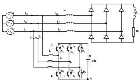
The active power filter was a recently developed piece of equipment for simultaneously delivering the compensating current to suppress the current harmonics on the ac side to make mains current sinusoidal. The active power filter is connected in parallel with nonlinear load. Active Power filters have wide application in modern electrical distribution system for eliminating the harmonics associated with it. Shunt active power filter (SAPF) is one of power filters which have better dynamic performance and it needs an accurate control algorithm that provides robust performance. The control methods are responsible for generating reference currents which are used to trigger the Voltage Source Inverters [2-3]. La Figure 1 presents the two -level three-phase shunt active power filter connected to balanced power grid (vsi for i = {1, 2, 3}) powering a three phase parallel-connected two diode rectifiers feeding variable series (R, L) loads. The filter is connected to the power grid through inductive filter Lf for each phase. The output currents of shunt active filter are controlled to provide a similar waveform of identified reactive and harmonic currents generated by the non-linear load (diode rectifiers).
Figure 1. General structure of a parallel active power filter
Figure 2 presents a block diagram of the proposed control system. The major advantage of this control principle is its simplicity and easiness to be implemented. The task of this control is to determine the current harmonic references to be generated by the active filter [4].
They are defined using classical active and reactive power method proposed by Akagi [5].
Figure 2. Block diagram of the harmonic currents identification
By supposing that the main power supply voltages are sinusoidal, current harmonic references will be calculated like indicated in [6-7].
(α, β) voltage components at connexion point of active filter (vα, vβ) and currents (iα, iβ) are defined by the classical Concordia transformation:
$\left[\begin{array}{l}x \alpha \\ x \beta\end{array}\right]=2 / 3\left[\begin{array}{ccc}1 & -1 / 2 & -1 / 2 \\ 0 & -\sqrt{3} / 2 & \sqrt{3} / 2\end{array}\right]\left[\begin{array}{l}x_{1} \\ x_{2} \\ x_{3}\end{array}\right]$ (1)
where x = {v, vs, i, iL}
The instantaneous real and imaginary powers, noted by p and q, are calculated by:
$\left[\begin{array}{l}p \\ q\end{array}\right]=\left[\begin{array}{cc}v \alpha & v \beta \\ -v \beta & v \alpha\end{array}\right]\left[\begin{array}{l}i \alpha \\ i \beta\end{array}\right]$ (2)
These powers are then filtered by high-pass filters, which gives ph and qh and the harmonic components of the currents will be:
$\left[\begin{array}{c}i_{h 1} \\ i_{h 2} \\ i_{h 3}\end{array}\right]=\frac{1}{v_{\alpha}^{2}+v_{\beta}^{2}}\left[\begin{array}{cc}1 & 0 \\ -1 / 2 & -\sqrt{3} / 2 \\ -1 / 2 & \sqrt{3} / 2\end{array}\right]\left[\begin{array}{cc}v_{\alpha} & v_{\beta} \\ -v_{\beta} & v_{\alpha}\end{array}\right]\left[\begin{array}{c}p_{h} \\ q_{h}\end{array}\right]$ (3)
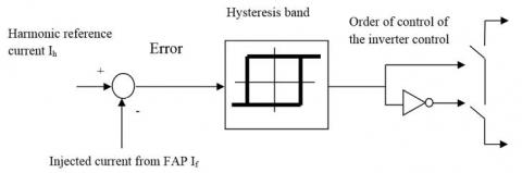
Hysteresis current control is a method of generating the required triggering pulses by comparing the error signal with that of the hysteresis band and it is used for controlling the voltage source inverter so that the output current is generated from the filter will follow the reference current waveform is shown in Figure 3.
Figure 3. Principle of current control by hysteresis
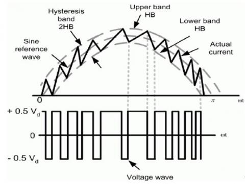
This method controls the switches of the voltage source inverter asynchronously to ramp the current through the inductor up and down, so that it follows the reference current. Hysteresis current control is the easiest control method to implement in the real time. Figure 4 illustrates the ramping of the current between the two limits where the upper hysteresis limit is the sum of the reference current and the maximum error or the difference between the upper limit and the reference current and for the lower hysteresis limit, it is the subtraction of the reference current and the minimum error. Supposing the value for the minimum and maximum error should be the same. As a result, the hysteresis bandwidth is equal to two times of error.
Figure 4. Hysteresis Band
According to the operating principle of the inverter, the output voltages of each phase are significant to the switching pulses of the switches in each leg. As a result, the switching gates for the active power filter can be obtained. The voltage across the inductors show the frequency of the switching and the frequency can be altered by adjusting the width of the hysteresis tolerance band.
A fuzzy logic controller is based on a collection of control rules governed by the compositional rule of inference applied to maintain the constant voltage across the capacitor by minimizing the error between the capacitor voltage and it’s reference voltage [8], the block diagram of a such control is illustrated by the (figure 5).
Figure 5. Principle of current control by Fuzzy logic
A fuzzy logic controller (FLC) converts is advanced control strategy [9-10] the based fuzzy rules are constructed by expert experience or knowledge database. In the input of (FLC), the error e (k) and the Change of error Δe (k) have been placed of the angular velocity to be the input variables of the fuzzy logic controller. Then the output variable of (FLC) the fuzzy logic controller is presented by the control voltage μ (k), the type of fuzzy inference engine used is Mamdani. The linguistic input variables are defined as (N, Z, P,) which, negative,
zero, and positive respectively. In The output the linguistic variables are defined as (PB, PM, PS) which, positive big, positive mean and, positive small zero respectively. The fuzzy rules are summarized in (Table 1).
Table 1. Rule base table
|
e(t)
de(t)/dt |
NB |
NS |
Z |
PS |
PB |
|
N |
PB |
PS |
PS |
Z |
NB |
|
Z |
PB |
PS |
Z |
NS |
NB |
|
P |
PB |
Z |
NS |
NS |
NB |
The simulation is carried out using a program working in MATLAB Simulink environment. The simulation parameters are shown in table.2, presented below.
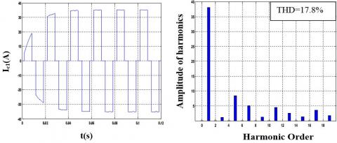
The frequency spectrum of the line currents presents the presence of several harmonics of amplitudes which coincide with those developed theoretically (THDI=17.8%)
Table 2. Simulation parameters
|
Source settings |
V=220 V, f=50 hz |
|
Lcc=5.10-3H |
|
|
Active filter settings |
Rf=0.2 Ω. |
|
Lf=0.004 H. |
|
|
Load parameters |
Rch1= 14.6 Ω. |
|
Rch2= 7.3 Ω. |
|
|
Lch= 0.155 H. |
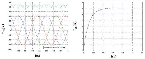
Figure 6. Load voltage and load current
Figure 7. Line current Ic1 and its spectrum before filtering
6.1 Simulations results using Hysteresis controller a band Δh=0.1A
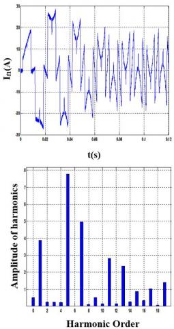
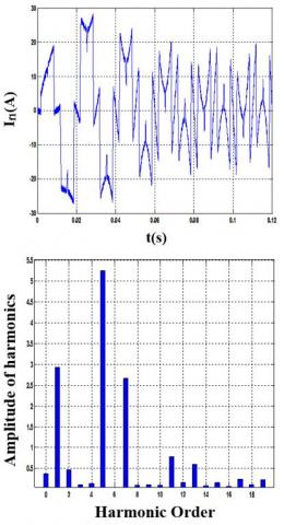
Figure 8. Current injected by the inverter and source current of the first phase
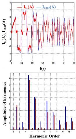
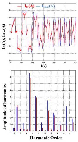
Figure 9. Reference current, injected and their spectra
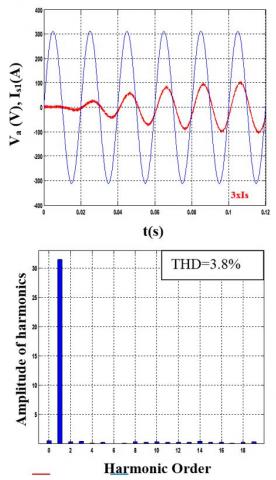
Figure 10. Voltage, current and current spectrum after filtering
6.2 Simulations results using Hysteresis controller a band Δh=1A
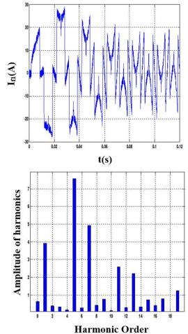
Figure 11. Current injected by the inverter and source current of the first phase
Figure 12. Reference current, injected and their spectra
Figure 13. Voltage, current and current spectrum after filtering
6.3 Simulations results using Fuzzy Logic Hysteresis Δh=0.1A
Figure 14. Current injected by the inverter and source current of the first phase
Figure 15. Reference current, injected and their spectra
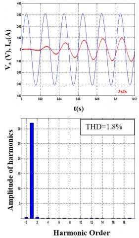
Figure 16. Voltage, current and current spectrum after filtering
6.4 Interpretation of results
The previous figures show:
- The improvement of the shape of the source currents after filtering.
- The fuzzy hysteresis technique improves the performance of the network compared to the fixed hysteresis strategy.
- The fuzzy hysteresis technique control has a good filtering quality.
- The decrease in fuzzy hysteresis band’s gain (from Δh=1 to Δh=0.1A) has allowed us to have more sinusoidal network currents.
The Power quality management has been the main problem that the industries are facing today. This is mainly affected by generation of harmonics. The growing use of electronic equipment produces a large amount of the harmonics in the distribution systems because of non-sinusoidal currents consumed by non-linear loads. In this paper and we clearly calculate the Total Harmonic distribution (THD) with shunt active power filter and without shunt active power filter. In this work, we have shown the effectiveness of Hysteresis and fuzzy controllers for harmonics mitigation using shunt APF. It is clearly understood that by using Hysteresis controller the harmonics level dropped to 2.08 % from 17.8 % when shunt APF is not connected, which is well below the restrictions imposed by IEEE Std. 519. In case of fuzzy logic controller, the THD was approx. 1.8%.
[1] Akagi, H. (1997) Control strategy and site selection of a shunt active filter for damping of harmonic propagation in power distribution systems. IEEE Transactions on Power Delivery, 12(1): 354-363. https://doi.org/10.1109/61.568259
[2] Benyettou, L., Benslimane, T., Bentata, K., Abdelkhalek, O. (2015). Open transistor faults characterization novel method for cascaded h-bridge five-level three-phase shunt active power filter. AMSE Journals, Modelling A, 88(1): 53-70.
[3] Benyettou, L., Benslimane, T., Abdelkhalek, O. (2017). Comparative study of different methods of active power compensation. AMSE Journals, Modelling A, 90(4): 310-327. https://doi.org/10.18280/mmc_a.900401
[4] Karimi, S., (2009). Continuity of service of three-phase power converters and prototyping “FPGA in the loop”: application to parallel active filter. Doctorate thesis, Henri Poincare University, Nancy-I, France.
[5] Akagi, H., Kanazawa, Y., Fujita, K., Nabae, A. (1983). Generalized theory of the instantaneous reactive power filter. Proceedings of International power electronics conference, Tokyo, Japan, 1983; 1375–1386.
[6] Mansour, B., Abselkader, B., Said, B. (2013). Sliding mode control using 3D-SVM for three-phase four-leg shunt active filter. International Journal of Power Electronics and Drive Systems (IJPEDS). 3(2): 147-154. https://doi.org/10.11591/ijpeds.v3i2.2012
[7] Benslimane, T., Aliouane, K. (2004). A new optimized SVPWM Technique Control for Autonomous Parallel Active Filter. 11th International Conference on Harmonics and Quality of Power. IEEE Transactions on Automatic Control, 112–116. https://doi.org/10.1109/ICHQP.2004.1409338
[8] Rathika, P., Devaraj, D. (2010). Fuzzy logic based approach for adaptive hysteresis band and dc voltage control in shunt active filter. International Journal of Computer and Electrical Engineering, 2(3): 1793-8163.
[9] Hamadi, A., Al-Haddad, K., Lagact, P.J., Chandra, A. (2004). Indirect current control techniques of Three Phase APF Using Fuzzy Logic and Proportional Integral Controller: Comparative analysis. International Conference on Harmonics and Quality of Power, https://doi.org/10.1109/ICHQP.2004.1409382
[10] Mekri, F., Machmoum, M., Mazari, B., Ahmed, N.A. (2007). Determination of Voltage References for Series Active Power Filter Based on a Robust PLL System. International Symposium on Industrial Electronics, 473-478. https://doi.org/10.1109/ISIE.2007.4374643