Nesrine Boulaktout | El Hacene Mezaache* | Abdelghani Laouer
© 2021 IIETA. This article is published by IIETA and is licensed under the CC BY 4.0 license (http://creativecommons.org/licenses/by/4.0/).
OPEN ACCESS
This paper investigates the effect of fins orientations of a horizontal two fins annular tube heat exchanger on enhancing the heat transfer during the melting process of n-eicosane, as phase change material (PCM) used in thermal storage systems. Based on the enthalpy-porosity method, two-dimensional model is performed and solved by Ansys Fluent. The impact of the fins orientation on melting rate, thermal conduction and natural convection, as the angle of the system varied from 0º (vertical fins) to 90º (horizontal fins) are discussed. Numerical predictions are validated by comparison with experimental data and numerical results reported in the literature. Good agreements are achieved. The results show that at initial time of the melting process, the conduction heat transfer is dominant. During the melting process, the heat transfer in the horizontal fins is more effective while the upper half of PCM melts and less effective as the lower half of PCM melts because fin arrangement resists natural convection occurs. However, the effectiveness of heat transfer and convection in the vertical fins is almost constant during the entire melting process. From comparison, better heat transfer performance is achieved with vertical fins system; complete melting was reduced 250% compared to horizontal fins case.
pcm melting, heat transfer enhancement, thermal storage, heat exchanger, natural convection, fins, annular tube
Currently, the fossil fuels satisfy high percentage of the total energy needs, and their direct impact on the climate is alarming. For this reason, research on renewable energies is currently a major focus of development [1-3].
Due to its main advantages of abundance and environmental cleanness, solar energy, as renewable energy, is a promising energy resource. However, solar energy intensity is unstable with different times, weathers, and seasons, which can limit the application of solar thermal system in some specific regions. The efficiency of the system and its reliability are strongly ensured by an adequate choice of a heat storage system which remains a major problem for the solar thermal system. Recently, thermal energy storage systems, especially latent heat thermal energy storage (LHTES) in phase change materials (PCMs), have gained a greater attention from the viewpoint of global environmental problems and the energy-efficiency improvement. PCMs, as thermally active materials, are increasingly used in different engineering fields, such as: heat and cold storage, thermal insulation of buildings, passive air conditioning, heat recovery, refrigeration, solar thermal collector, thermal regulation of systems ..., etc. [4-9].
Various numerical models have been developed over the years for the solution of the phase change problem. Such interested in thermal energy storage systems can be subdivided into two classes.
The first one is focused on the effect of system geometry and the numerical calculation techniques. Among these works:
Darzi et al. [10] studied the melting process of n-eicosane as PCM inside a cylindrical concentric and eccentric double pipe heat exchanger. They reported that the melting rate is approximately the same for concentric and eccentric model before 15 min and after this time the melting rate decreases in the concentric case.
Seddegh et al. [11] investigated the two-dimensional melting process of paraffin wax (RT 50) in the annulus of two concentric tubes and heat transfer fluid (HTF) in the tube. They reported that the horizontal energy storage system has better heat transfer performance, in particular during part-load energy charging; however, the thermal behavior does not show any significant difference in the horizontal and vertical energy storage units in the discharge process.
Hong et al. [12] considered the melting of paraffin wax in two dimensional rectangular cavity with partially thermally active walls. They revealed that inclination angle, aspect ratio and number of discrete heat source have a significant influence on the time for complete melting.
Fadl and Eames [13] used Lauric acid as PCM to study the effect of mushy zone parameter on melting fraction and heat transfer characteristics. They found that proper selection of the mushy zone constant is essential for the accurate prediction of heat transfer characteristics within a PCM, where smallest values give unrealistic predictions of the melt front development and higher values delayed prediction of melting in the PCM.
Bouteldja et al. [14] investigated the effect of the aspect ratio and Grashof number on the convection diffusion phenomena associated with solid liquid phase transition processes during PCM solidification within a rectangular cavity. They reported that the solidification phase change process depends considerably on the thermal and geometrical parameters of the system. Additionally, it is demonstrated that the physical approach based on a purely conductive model remains valid to cases of low values of Grashof number and aspect ratio.
The second class of works aims to improve the efficiency of thermal storage systems where several technical solutions have been adopted. It consists in increasing the heat exchanges within PCM fluids by the incorporation of fins, the addition of nanoparticles, the simultaneous use of fins and nanoparticles or a porous medium. The published works can be grouped according to the adopted technique. We distinguish:
For the PCM-fins case:
Mat et al. [15] simulated a two-dimensional melting process of the RT82 as a PCM in a triplex-tube heat exchanger. They concluded that the complete melting using a triplex-tube heat exchanger with internal-external fins with the longest length fin was reduced to 43.3% compared with the triplex tube without fins.
Al-Abidi et al. [16] analyzed the effect of two dimensional heat transfer enhancement for a triplex tube heat exchanger by using internal and external fins to accelerate the melting rate of RT82 as a PCM. They indicated that the effect of fin thickness is small compared to the fin length and number of fins.
Eslamnezhad and Rahimi [17] investigated the enhancement of heat transfer method using rectangular fins to melt the RT82 as phase-change material in a triplex tube heat exchanger. The predicted numerical results show that the impact of fin location on melting is very important in triplex type heat exchangers and the best fin arrangement could improve the melting time by 17.9%.
Joybari et al. [18] considered the simultaneous charging and discharging (SCD) of phase change material using RT31 inside triplex tube heat exchanger. They reported that depending on the initial PCM condition, different final solid-liquid interfaces were found, and the pure conduction model could be applied just for the initially fully melted PCMs under SCD.
Xu et al. [19] examined the temperature field of cold storage truck and cold storage plate of phase change material melting where NaCl is used as phase change material. They showed that the melting rate can be significantly increased with rise of environment temperature and the time of latent heat storage discharge will be shorter.
Talukdar et al. [20] investigated the charging and discharging of LHTES system which is an evaporator tube inside a PCM (water) filling a rectangular box. They indicated that faster solidification, as well as a higher energy storage capacity and heat flux during melting is found for the PCM pack of 6.5 cm thickness with higher number of fins.
For the PCM-nanoparticles case:
Arıcı et al. [21] discussed the melting of paraffin wax enhanced with Al2O3 nanoparticles in a square enclosure with partially thermally active walls. They concluded that the heat energy stored by PCM can be enhanced by changing orientation of thermally active walls of the enclosure, dispersing nanoparticules or applying both simultaneously.
Iachachene et al. [22] inspected the melting of paraffin wax in trapezoidal cavity. Grapheme nanoparticles were added to the phase-change materials to improve the system's efficiency associated with the orientation effect. It was observed that both effects are beneficial for heat transfer enhancements in PCMs.
Chamkha et al [23] investigated the melting process of a nano-enhanced phase change material in a square cavity with a hot cylinder located in the middle of the cavity in the presence of both single and hybrid nanoparticles. The authors showed that the solid-liquid interface and the liquid fraction are significantly affected by the volume fraction of nanoparticles and the thermal conductivity parameter.
Boukani et al. [24] investigated the melting of the nano-PCM of n-octadecane paraffin dispersed with Cu nanoparticles in partially filled horizontal elliptical capsules with different aspect ratios (AR). They concluded that for a given AR, the presence of nanoparticles enhances the melting rate and decreases the volume change of NePCM as compared to the pure PCM case.
For the PCM-fins-nanoparticles case:
Abdulateef et al. [25] analyzed the performance of a PCM triplex-tube heat exchanger using a combination of fins-nanoparticles. The results show that the external triangular fins-nanoparticle model which has fins number (8), fins length (141 mm) and fins aspect ratio (18%) considered the most efficient to minimize the melting and solidification times.
Mahdi et al. [26] investigated the heat transfer enhancement applying longitudinal fins with nanoparticles with a view to achieving better energy recovery process in the triplex-tube TES system. They found that the application of fins alone shows better enhancement than using either nanoparticles alone or combination of fins and nanoparticles.
Keshteli and Sheikholeslami [27] studied the solidification of RT82 within a three-dimensional triplex tube. The authors investigated the impacts of using nanoparticles, fins, and the combination of both of them on thermal characteristics during solidification in an energy storage unit. They found that using both nanoparticles and fins simultaneously has a significant impact on freezing time.
For the PCM-porous medium case:
Sardari et al. [28] investigated the effect of a high conductivity porous medium for the copper foam LHTES system. They reported that the presence of a porous medium increases the heat transfer significantly, but the improvement in melting performance is strongly related to the system’s dimensions.
Huo et al. [29] employed the porous medium to enhance the heat transfer of the PCM. They investigated the effects of the Rayleigh number and porosity on the heat transfer process in battery thermal management (BTM). The results show that decreasing the porosity will accelerate the melting rate. When the porosities are 0.9, 0.8, 0.7, and 0.6, the total melting times are decreased by 23.7%, 43.3%, 58.0%, and 75.4%, compared with pure PCM.
Mehryan et al. [30] examined the melting process of a PCM inside an inclined compound enclosure partially filled with a porous medium. They showed that the rates of melting and heat transfer are enhanced as the thickness of the porous layer increases. The melting rate is the highest when the inclination angle of the enclosure is 45°. An increase in the wall thickness improves the melting rate.
Shahsavar et al. [31] performed a numerical investigation for evaluating the impact of porous medium and surface waviness on the melting and solidification of composite PCM in a vertical double-pipe LHTES. Their results indicated that the total melting and solidification time can be significantly reduced by up to 91.4% and 96.7% when using porous structures with high conductivity and wavy channel, respectively.
The present numerical study investigated the heat transfer during PCM melting in a horizontal annular tube heat exchanger. Two geometrical models, based on horizontal and vertical fins, respectively, are considered. The effect of fins orientation on the melting process were developed and studied. Liquid fraction, streamlines and temperatures contours are illustrated. Heat flux and heat transfer coefficient are presented and compared.
The paper is structured as follows: Section 2 describes the physical model. Section 3 presents the mathematical formulation and numerical method used for the computation and the validation. The numerical results are discussed in Section 4. Finally, concluding remarks are presented in Section 5.
A two dimensional geometry of an annular thermal energy storage system is shown in Figure 1. It consists of two concentric cylindrical tubes made of copper. The outer cylinder tube with a radius of 20 mm is thermally insulated. The inner cylinder tube with a radius of 10 mm and 1.5 mm thickness is subjected to an imposed hot temperature. The annular space is filled with a solid PCM.
Figure 1. Schematic representation of the annular tube heat exchanger (HT: hot tube, IT: insulated tube)
Figure 2. Schematic representation of the investigated cases
To increase the heat transfer rate and to ensure high thermal conductivity, rectangular copper fins with 8 mm long and 1 mm thick were fixed to the inner tube. Two different fins orientation were studied Figure 2: horizontal fins (geometry 2) and vertical fins (geometry 3).
It may be noted that the fluid flow and heat transfer are symmetrical with respect to the vertical axis of the annular system.
The phase change material n-eicosane is considered in this study with thermo-physical properties at solid and liquid states, listed in Table 1 [32]. The dependence of the thermophysical properties of the PCM on the temperature is expressed using user defined function [33, 34].
Table 1. Thermophysical properties of n-eicosane [32]
|
Physical Properties |
Solid (T£Tsol) |
Liquid (T³Tliq) |
|
density, r (kg/m3) |
910 |
769 |
|
thermal, conductivity, k (W/m.K) |
0.423 |
0.146 |
|
specific heat capacity, cp (J/kg.K) |
1926 |
2400 |
|
thermal expansion coefficient, b (K-1) |
|
8.161×10⁻⁴ |
|
melting point, Tm (°C) |
36.4 |
|
|
latent heat of fusion, L (kJ/kg) |
248 |
- |
|
mushy zone range temperature, DT |
0.1 |
|
|
Mushy zone domain, Tsol£T£Tliq |
|
|
|
solidus temperature, Tsol (K) |
Tm-DT/2 |
|
|
liquidus temperature, Tliq(K) |
Tm+DT/2 |
|
|
reference temperature, Tref |
Tliq |
|
3.1 Assumptions
The mathematical formulation of the melting process of the PCM inside the annulus cylinder is expressed under the following assumptions:
The flow is Newtonian, two-dimensional, laminar, unsteady and incompressible. The viscous dissipation is negligible. Boussinesq approximation is applied for buoyancy effects. The superheat and the volume expansion due to phase change are negligible.
3.2 Mathematical modeling
The melting problem is formulated using the enthalpy porosity method [10]. Under the prescribed assumptions, the model equations expressed in Cartesian coordinates system are as follows:
Continuity equation:
$\frac{\partial \rho}{\partial t}+\frac{\partial(\rho u)}{\partial x}+\frac{\partial(\rho v)}{\partial y}=0$ (1)
x-momentum equation:
$\frac{\partial(\rho u)}{\partial t}+\frac{\partial(\rho u u)}{\partial x}+\frac{\partial(\rho u v)}{\partial y}=\frac{\partial}{\partial x}\left(\mu \frac{\partial u}{\partial x}\right)$
$+\frac{\partial}{\partial y}\left(\mu \frac{\partial u}{\partial y}\right)-\frac{\partial p}{\partial x}+\rho g_{x}+S_{x}$ (2)
y-momentum equation:
$\frac{\partial(\rho v)}{\partial t}+\frac{\partial(\rho v u)}{\partial x}+\frac{\partial(\rho v v)}{\partial y}=\frac{\partial}{\partial x}\left(\mu \frac{\partial v}{\partial x}\right)$
$+\frac{\partial}{\partial y}\left(\mu \frac{\partial v}{\partial y}\right)-\frac{\partial p}{\partial y}+\rho g_{y}+S_{y}$ (3)
Energy equation:
$\frac{\partial(\rho h)}{\partial t}+\frac{\partial(\rho u h)}{\partial x}+\frac{\partial(\rho v h)}{\partial y}+\frac{\partial(\rho \Delta H)}{\partial t}$
$=\frac{\partial}{\partial x}\left(k \frac{\partial T}{\partial x}\right)+\frac{\partial}{\partial y}\left(k \frac{\partial T}{\partial y}\right)$ (4)
In these equations, u is the x-axis velocity component, u the y-axis velocity component, r the PCM density, m the dynamic viscosity, p the pressure, g the gravitational acceleration and k the thermal conductivity. The quantity H is the enthalpy of a control volume subjected to phase change. It is equal to the sum of sensible heat enthalpy (h) and the latent heat enthalpy (DH), defined as:
$h=h_{\text {ref }}+\int_{T_{\text {ref }}}^{T} c_{p} d T$ (5)
$\Delta H=\phi L$ (6)
$H=h+\Delta H$ (7)
where, href is the reference enthalpy at the reference temperature Tref, cp the specific heat, L the latent heat of the PCM. The reference temperature is generally chosen equal to liquidus temperature (Tliq) where melting PCM and consequently buoyancy effects are present.
In momentum equation, Boussinesq approximation was introduced to account for the natural convection process in the melted PCM [11]:
$\rho=\rho_{l}\left[1-\beta\left(T-T_{l}\right)\right]$ (8)
and the source term is expressed as:
$\left\{\begin{array}{l}S_{x}=-A(\phi) u \\ S_{y}=-A(\phi) \cup\end{array}\right.$ (9)
where, f is the ratio between the molten PCM volume and the total volume of PCM in a computational cell, respectively.
$\left\{\begin{array}{l}\phi=0 \text { if } T \leq T_{\text {sol }} \\ \phi=\frac{T-T_{\text {sol }}}{T_{\text {liq }}-T_{\text {sol }}} \text { if } T_{\text {sol }} \prec T \prec T_{l i q} \\ \phi=1 \text { if } T \geq T_{l i q}\end{array}\right.$ (10)
and A is the porosity function, defined as [35]:
$A(\phi)=\frac{C(1-\phi)^{2}}{\phi^{3}+\varepsilon}$ (11)
C is a constant that reflect the mushy zone morphology. It describes how steeply the velocity is reduced to zero when the material solidifies. This constant is situated between 104-107, so 105 is considered for this work [36]. ε is a small number (0.001) to prevent division by zero.
3.3 Initial and boundary conditions
In all three considered cases, the outer surface of the annulus heat exchanger is adiabatic. The PCM is initially solid and subcooled at 23℃. The inner wall temperature of cylinder and fins are fixed to 70℃. The impermeability and no-slip boundary conditions were applied at the annulus walls (u= u= 0).
3.4 Numerical procedure and validation
The numerical solution of the developed model was conducted using Ansys Fluent. It uses the finite volume method [37] and the enthalpy-porosity technique for modeling the solidification/melting process.
In this enthalpy approach, the liquid volume fraction in each control volume is calculated at each iteration. When the region is entirely solid, the porosity is zero and also the flow velocity in that zone also drops to zero. The transient discretization is based on the second order-upwind scheme. Semi-implicit pressure-linked equations (SIMPLE) algorithm was used for pressure-velocity coupling and PRESTO for pressure correction.
Three simulations of different time step sizes (0.1 s, 0.05 s, 0.01 s) were investigated (Figure 3), a time step of 0.05 s was finally selected to achieve the convergence criteria (10-4), as 0.01s and 0.05s produce nearly same results.
in order to check mesh independency, the results of the instantaneous PCM mean temperature were obtained by different grid sizes for each model and presented in Table 2. The final grid resolution considered for each case was summurized in Table 3.
Figure 3. Time step optimization
Table 2. Grid size independency verification for the studied cases based on PCM mean temperature with 0.05 s time step
|
Without fins |
|||
|
Grid size |
300 s |
900 s |
1500 s |
|
3388 |
314.9720 |
332.9872 |
336.0756 |
|
9045 |
314.6768 |
332.7419 |
336.0614 |
|
13869 |
314.2612 |
332.3935 |
335.9831 |
|
Horizontal fins |
|||
|
Grid size |
300 s |
900 s |
1500 s |
|
3330 |
319.8244 |
335.2292 |
336.9254 |
|
8964 |
319.2702 |
335.1249 |
336.8697 |
|
13032 |
319.2083 |
335.1037 |
336.8622 |
|
Vertical fins |
|||
|
Grid size |
300 s |
600 s |
900 s |
|
3402 |
321.5140 |
333.5577 |
340.8104 |
|
8847 |
319.9799 |
332.0596 |
340.6408 |
|
13032 |
319.7392 |
331.7738 |
340.5795 |
Table 3. Grid resolution used for each case.
|
Case |
Grid size |
|
Without fins |
9045 |
|
Horizontal fins |
8964 |
|
Vertical fins |
8847 |
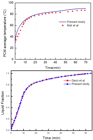
First, experimental data from an earlier study [15] was used for validation of the melting process.
In the experiment the melting process was in a triplex-tube heat exchanger with internal and external fins to enhance the heat transfer. The HTF and PCM are water and paraffin RT82 (Rubitherm Technologies GmbH). Initial average temperature of the PCM was 27℃ with phase change temperature range of 77-85℃, whereas the HTF temperature was maintained at 90℃.
Figure 4 compares the simulated PCM average temperature with the experiment of a triplex tube heat exchanger. A good agreement can be seen from the comparison, which verifies the reliability of the numerical model for solving the phase change problem.
Additionally First, the numerical predictions are validated by comparison with numerical results from the literature [10]. Good agreement is obtained as can be seen on Figure 4 for melt fraction versus time.
Figure 4. Comparison of the numerical predictions with experimental data (Mat et al. [15]) and numerical results (Darzi et al. [10])
The study investigated the melting of n-eicosane PCM in tube annular heat exchanger under the thermal conditions defined in section 3.3. The numerical results were recorded at several selected times for a complete melting cycle, and represented as isotherms, streamlines, liquid fraction contours in addition the heat flux and heat transfer coefficient as time progress.
4.1 Geometry 1
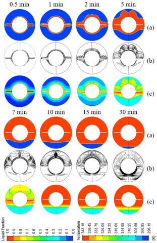
Figure 5 presents the liquid fraction (a), streamlines (b) and isotherms (c) contours for different time periods (0.5, 1, 2, 5, 7, 10, 15 and 30 min). In the first stage of the system, the solid PCM absorbed heat from the inner tube surface and starts melting when the temperature reaches the melting point.
According to Figure 5, after 1 minute of melting, the melting front shape is almost circular. This is due to the fact that heat transfer occurred between the hot inner tube wall and the cold PCM by thermal conduction which dominated the melting process at the early stage; it caused a thin layer of liquid to form in the narrow melting area. However, after a moment of 5 min, the solid-liquid interface expanded with respect to time and the melting fronts were dominated by the buoyancy-driven currents which influence the melted regions of PCM. Consequently, the buoyancy force drives circulation in the melted PCM Figure 5(b).
Figure 5. Melting front (a), streamlines contours (c) and isotherms (c): Case A1
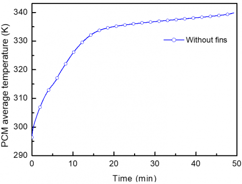
The molten PCM moved upward, and reached its maximum temperature in the upper portion of the container and returns downward to complete the natural convection circle. The convection circles became more sufficient and as the liquid fraction volume is increased, the upper half was greater than the lower one, the melting rate and mean temperature increase considerably Figures 6-7. However, the increase rate turns to be mild once the top zone of the system is full of liquid PCM, the temperature in the melted PCM becomes more uniform. The entire PCM domain was melted after 48 minutes Figure 6.
Figure 6. Liquid fraction versus time
Figure 7. Mean temperature versus time
4.2 Geometry 2
The application of fins embedded in the PCM is the basis of most heat enhancement techniques because of its simplicity, easy fabrication, and low construction cost [38].
In this investigation, the way for showing the effect of the fins location on the development of PCM melting is to rotate the annular tube heat exchanger.
Figure 8 shows the liquid fraction (a), streamlines (b), and temperature (c) contours at several selected times (0.5, 1, 2, 5, 7, 10, 15 and 30 min) for horizontal fins case.
At early times, a thin melting layer is formed in the upper section of the fins Figure 8(a). The heat transfer in the melt zone was dominated by conduction. After that time, the non-uniformity of the melt layer thickness that is in evidence in the streamline diagrams is confirmed. At time t = 2 min, waviness on the solid-liquid interface near the top region of the annulus is observed which results in unstable and complicated melting structure. It implies the formation of multi-convection cells in the liquid PCM which shows the Benard formation in natural convection Figure 8(b) and the melting process was accelerated Figure 15. At t ≥ 7 min, the melting slowed down Figure 15 because of unmelted specimen in the annulus.
Complete melting was difficult to achieve at the bottom region of the annular tube because the fins are blocking the heat moving to the top section and hence resist to natural convection that occurs during the charging process.
Figure 8. Melting front (a), streamlines contours (c) and isotherms (c) for the horizontal fins configurations
The top section performs a large variation of melt thickness compared to the bottom: better melting development, higher temperature rises due the influence of natural convection heat transfer which plays an important role at this zone.
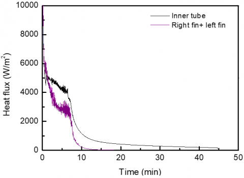
The practical way to study the thermal behavior and show the overall heat transfer ability from the heating boundary in the PCM charging progress in latent heat thermal energy storage systems is to calculate the average heat flux at the heated boundary and find the charged power. Different experimental and numerical works [39-42] presented the heat flux quantity and show it fluctuating character with a peak at initial time. It is noted that present predicted results for the variation of the heat flux with time are similar to these works. The average heat flux and the corresponding average heat transfer coefficient are related by the following expression: $\varphi_{\mathrm{av}}=h_{\mathrm{av}}\left(T_{h}-T_{\mathrm{av}}\right)$, where $T_{h}$ is the surface hot temperature and $T_{\mathrm{av}}$ is the PCM average temperature.
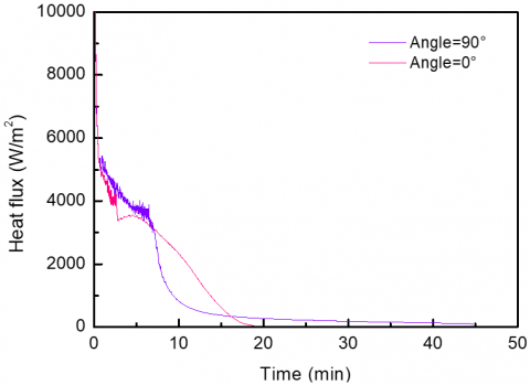
Figures 9-10 show the charged heat flux of inner tube surface and fins and the deduced corresponding heat transfer coefficients for the case of horizontal fins configurations.
As the phenomenon was symmetric, the same results were found for the right and the left fins. At the beginning, a peak is detected. That may be caused by the higher temperature difference between the hot temperature of inner tube surface and the solid PCM. After that time, it drops rapidly during the initial conduction dominated stage. This is followed by sudden change in the slope indicating that natural convection is established in the system. Almost a constant value of heat flux can be observed during this stage for both surfaces. In such span of time the charge process proceeds at a constant rate. From the graph, the heat flux and heat transfer coefficient for the inner tube was higher compared with fins values.
Figure 9. Heat flux as function of time for the horizontal fins configurations
Figure 10. Heat transfer coefficient as function of time for the horizontal fins configurations
4.3 Geometry 3
Figure 11 depicts the contours of liquid fraction (a), streamlines (b) and temperature (c) of the PCM at different times (0.5, 1, 2, 5, 7, 10, 15, 30 min).
As seen in the figure, at the initial period of melting process, the solid PCM absorbs thermal energy from the inner tube and fins.
The melting starts and progresses gradually parallel to the hot surface symmetrically. At this stage, the isotherms in the melted liquid are nearly vertical Figure 11 (c) and the heat transfer through annulus is mainly by conduction. At t ≥ 2 min melted liquid heated by the inner tube and fins rises up along the fins and descends along the melting interface. A cellular flow is established due to onset of convection Figure 11 (b) and (c). At t ≥7 min, the liquid PCM gradually fills the upper region of the annulus. The whole melting process is active by convective heat transfer mode. The melting rate was almost constant for the entire melting process and it was noticed by the curve slope of the PCM's liquid fraction in Figure 15. In this case, the orientation of the fins plays an important role on the melting due to onset of convection, better natural convection heat transfer represented by higher melted fraction.
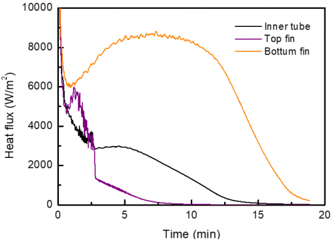
Figures 12-13 show the evolution of the charged heat flux and heat transfer coefficient of inner tube and fins. It can be seen that these quantities differ between the studied surfaces in vertical fins case. As expected, faster melting is due to higher heat flux exchange.
During the first phase of the melting process, the charged heat flux is very high, based on the high temperature difference between the hot surface temperature and the cold PCM. After that time, the heat flux rate drops rapidly during the initial conduction dominated stage.
Figure 11. Melting front (a), streamlines contours (c) and isotherms (c) for the vertical fins configurations
Figure 12. Heat flux as function of time for the vertical fins configurations
Figure 13. Heat transfer coefficient as function of time for the vertical fins configurations
4.4 Effect of fin orientation
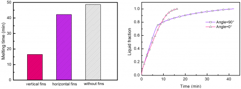
Figures 14-16 show the effect of fins orientation on the melted PCM contours, liquid fraction, total melting time, average PCM temperature and energy stored during a melting process for the studied cases of the annular heat tube exchanger.
It is illustrated how the melting rate and heat transfer are affected by the fins arrangement in the annulus. As can be seen, the curves have approximately linear behavior for the two cases in the time interval (0-7 min) and the rate of melting and energy stored in both models is almost the same. After that time, the melting slowed down for the indirect fins (horizontal fins) because the fins arrangement blocks the flow of the melting PCM and hence resists natural convection that occurs during charging. Meanwhile, direct arrangement (vertical fins) allows fluid flow through the heat exchanger in such a way that the hot liquid goes toward the top and the cold material moves toward the lower part freely. The complete melting for direct fins happens at 16 minutes whereas this time for indirect fins is 42 minutes which is showing 26 minutes difference.
This difference means a reduction factor 2.5 in melting time. Direct design performs superior as compared to other design: higher melted fraction Figure 15, better natural convection heat transfer represented by higher temperature rise Figure 16.
Also, it is noted that similar behavior in liquid fraction and energy stored curves was observed which is clearly raisonable as the dominant thermal energy storage was by latent heat type.
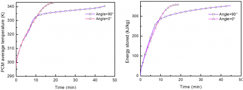
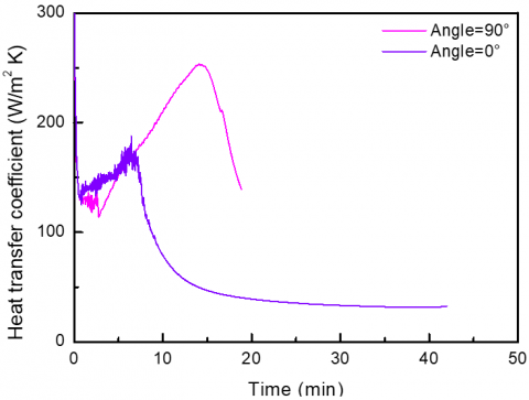
The comparison of heat transfer rate and heat transfer coefficient for both models are presented in Figures 17-18, horizontal fins tend to spend more time for complete melting process than vertical fins model. This can be explained due to the influence of the dominant heat transfer type on the melting process.
Convection heat transfer has a higher contribution in melting and helps to increase the heat transfer coefficient and to reduce the time for complete melting.
Figure 14. Comparison of melt fraction contour between the horizontal and vertical fins configurations
Figure 15. Comparison of total melting time and liquid fraction versus time between horizontal and vertical fins configurations
Figure 16. Comparison of mean temperature and energy stored versus time between horizontal and vertical fins configurations
Figure 17. Comparison of heat flux between horizontal and vertical fins configurations
Figure 18. Comparison of heat transfer coefficient between horizontal and vertical fins configurations
Heat transfer enhancement for an annular heat tube exchanger by using fins to accelerate the melting rate of n-eicosane as a PCM was investigated numerically.
For the numerical analysis, the enthalpy-porosity formulation was used for modeling combined convection-diffusion phase change; this method found the melting front within the PCM over time. The model predicts the effect of using metal fins to enhance the heat transfer and the effect of their orientation (horizontal and vertical case) on the thermal performance.
Different parameters including PCM average temperature, liquid fraction, heat flux and heat transfer coefficient were analyzed.
The numerical results of the melting process have shown that primary heat conduction is the dominant heat transfer mechanism. The thermal behavior at this stage does not show any significant difference in two cases. With the increase of melted region, natural convection becomes dominant and plays the key role for the melting process. The upward melted PCM motion greatly affected the upper half of the system. This, results in a faster melting progress at the top of the annulus compared to the bottom. In horizontal fins case, the fins block the heat moving to the top section and hence resist natural convection that occurs during the charging; hence such configuration was not helpful for the melting process.
By use of this experience and considering the fact that the PCM material in the lower part of the heat exchanger is the last part which melts, allocating fins to the lower half make the melting quicker and the heat transfer enhanced. Vertical fins have been introduced. This geometry has improved the melting time. The complete melting time using vertical fins orientation was reduced with a factor 2.5 compared to horizontal case.
This research work is supported by the DGRSDT, Algerian ministry of higher education and scientific research.
|
C |
mushy zone constant, kg.m-2.s-1 |
|
cp |
specific heat of PCM, J.kg-1.K-1 |
|
gi |
gravity acceleration in the i-direction, m.s-2 |
|
h |
sensible enthalpy, J.kg-1 |
|
H |
enthalpy, J.kg-1 |
|
k |
thermal conductivity, W.m-1.K-1 |
|
L |
latent heat of fusion, J.kg-1 |
|
p |
pressure, Pa |
|
R |
tube radius, m |
|
Si |
momentum source term in the i-direction, Pa.m-1 |
|
T |
temperature |
|
u |
x-velocity component, m.s-1 |
|
υ |
y-velocity component, m.s-1 |
|
Greek symbols |
|
|
ρ |
fluid density, J.kg-1.K-1 |
|
β |
thermal expansion coefficient, K-1 |
|
μ |
dynamic viscosity, kg.m-1.s-1 |
|
Subscripts |
|
|
av |
average |
|
h |
hot |
|
ini |
initial |
|
m |
melting |
|
ref |
reference |
|
s |
solidus |
|
l |
liquidus |
|
t |
time |
[1] Abdulmunem, A.R., Abed, A.H., Hussien, H.A., Samin, P.M., Rahman, H.A. (2019). Improving the performance of solar air heater using high thermal storage materials. Annales de Chimie - Science des Matériaux, 43(6): 389-394. https://doi.org/10.18280/acsm.430605
[2] Komolafe, C.A., Waheed, M.A. (2018). Design and fabrication of a forced convection solar dryer integrated with heat storage materials. Annales de Chimie - Science des Matériaux, 42(1): 23-39. https://doi.org/10.3166/ACSM.42.23-39
[3] Longeon, M., Soupart, A., Fourmigué, J.F., Bruch, A., Marty, P. (2013). Experimental and numerical study of annular PCM storage in the presence of natural convection. Applied Energy, 112: 175-184. http://dx.doi.org/ 10.1016/j.apenergy.2013.06.007
[4] Agyenim, F., Hewitt, N., Eames, P., Smyth, M. (2010). A review of materials, heat transfer and phase change problem formulation for latent heat thermal energy storage systems (LHTESS). Renewable and Sustainable Energy Reviews, 14(2): 615-628. https://doi.org/10.1016/j.rser.2009.10.015
[5] Alkilani, M., Sopian, K., Alghoul, M., Sohif, M., Ruslan, M. (2011). Review of solar air collectors with thermal storage units. Renewable and Sustainable Energy Reviews, 15(3): 1476-1490. https://doi.org/10.1016/j.rser.2010.10.019
[6] Sharma, S., Iwata, T., Kitano, H., Sagara, K. (2005). Thermal performance of a solar cooker based on an evacuated tube solar collector with a PCM storage unit. Solar Energy, 78(3): 416-426. https://doi.org/10.1016/j.solener.2004.08.001
[7] Ermis, K., Erek, A., Dincer, I. (2007). Heat transfer analysis of phase change process in a finned -tube thermal energy storage system using artificial neural network. International Journal of Heat and Mass Transfer, 50: 3163-3175. https://doi.org/10.1016/j.ijheatmasstransfer.2006.12.017
[8] Li, D., Wu, Y., Wang, B., Liu C., Arıcı, M. (2020). Optical and thermal performance of glazing units containing PCM in buildings: A review. Construction and Building Materials, 233: 117327. https://doi.org/10.1016/j.conbuildmat.2019.117327
[9] Benbrika, M., Teggar, M., Benbelhout, M., Ismail, K.A.R. (2020). Numerical study of N-Eicosane melting inside a horizontal cylinder for different loading rates. International Journal of Heat and Technology, 38(1): 125-130. https://doi.org/10.18280/ijht.380113
[10] Darzi, A.R., Farhadi, M., Sedighi, K. (2012). Numerical study of melting inside concentric and eccentric horizontal annulus. Applied Mathematical Modelling, 36(9): 4080-4086. https://doi.org/10.1016/j.apm.2011.11.033
[11] Seddegh, S., Wang, X., Henderson, A.D. (2016). A comparative study of thermal behaviour of a horizontal and vertical shell-and-tube energy storage using phase change materials. Applied Thermal Engineering, 93: 348-358. https://doi.org/10.1016/j.applthermaleng.2015.09.107
[12] Hong, Y., Ye, W.B., Huang, S.M., Yang, M., Du, J. (2018). Thermal storage characteristics for rectangular cavity with partially active walls. International Journal of Heat and Mass Transfer, 126: 683-702. https://doi.org/10.1016/j.ijheatmasstransfer.2018.05.005
[13] Fadl, M., Eames, P.C. (2010). Numerical investigation of the influence of mushy zone parameter Amush on heat transfer characteristics in vertically and horizontally oriented thermal energy storage systems. Applied Thermal Engineering, 151: 90-99. https://doi.org/10.1016/j.applthermaleng.2019.01.102
[14] Bouteldja, M., Mezaache, E.H., Laouer, A. (2019). Numerical study of the solidification of phase change materials in a rectangular cavity: Effects of convection and aspect ratio. Annales de Chimie: Science des Materiaux, 43(1): 1-9. https://doi.org/10.18280/acsm.430101
[15] Mat, S., Al-Abidi, A.A., Sopian, K., Sulaiman M.Y., Mohammad, A.T. (2013). Enhance heat transfer for PCM melting in triplex tube with internal-external fins. Energy Conversion and Management, 74: 223-236. https://doi.org/10.1016/j.enconman.2013.05.003
[16] Al-Abidi, A.A., Mat, S., Sopian, K., Sulaiman, M.Y., Mohammad, A.T. (2013). Internal and external fin heat transfer enhancement technique for latent heat thermal energy storage in triplex tube heat exchangers. Applied Thermal Engineering, 53(1): 147-156. https://doi.org/10.1016/j.applthermaleng.2013.01.011
[17] Eslamnezhad, H., Rahimi, A.B. (2017). Enhance heat transfer for phase-change materials in triplex tube heat exchanger with selected arrangements of fins. Applied Thermal Engineering, 113: 813-821. https://doi.org/10.1016/j.applthermaleng.2016.11.067
[18] Joybari, M.M., Haghighat, F., Seddegh, S. (2017). Numerical investigation of a triplex tube heat exchanger with phase change material: Simultaneous charging and discharging. Energy and Buildings, 139: 426-438. https://doi.org/10.1016/j.enbuild.2017.01.034
[19] Xu, X., Zhang, X., Munyalo, J.M. (2017). Simulation study on temperature field and cold plate melting of cold storage refrigerator car. Energy Procedia, 142: 3349-3400. https://doi.org/10.1016/j.egypro.2017.12.476
[20] Talukdar, S., Afroz, H.M.M., Hossain, M.A., Aziz, M.A., Hossain, M.M. (2019). Heat transfer enhancement of charging and discharging of phase change materials and size optimization of a latent thermal energy storage system for solar cold storage application. Journal of Energy Storage, 24: 100797. https://doi.org/10.1016/j.est.2019.100797
[21] Arıcı, M., Tütüncü, E., Kan, M., Karabay, H. (2017). Melting of nanoparticle-enhanced paraffin wax in a rectangular enclosure with partially active walls. Int. Journal of Heat and Mass Transfer 104: 7-17. https://doi.org/10.1016/j.ijheatmasstransfer.2016.08.017
[22] Iachachene, F., Haddad, Z., Oztop, H.F., Abu-Nada, E. (2019). Melting of phase change materials in a trapezoidal cavity: Orientation and nanoparticles effects. Journal of Molecular Liquids, 292: 110592. https://doi.org/10.1016/j.molliq.2019.03.051
[23] Chamkha, A.J., Doostanidezfuli, A., Izadpanahi, E., Ghalambaz, M. (2017). Phase-change heat transfer of single/hybrid nanoparticles-enhanced phase-change materials over a heated horizontal cylinder confined in a square cavity. Advanced Powder Technology, 28(2): 385-397. https://doi.org/10.1016/j.apt.2016.10.009
[24] Boukani, N.H., Dadvand, A., Chamkha, A.J. (2018). Melting of a Nano-enhanced Phase Change Material (NePCM) in partially-filled horizontal elliptical capsules with different aspect ratios. International Journal of Mechanical Sciences, 149: 164-177. https://doi.org/10.1016/j.ijmecsci.2018.09.056
[25] Abdulateef, A.M, Abdulateef, J., Sopian, K., Mat, S., Ibrahim, A. (2019). Optimal fin parameters used for enhancing the melting and solidification of phase-change material in a heat exchanger unite. Case Studies in Thermal Engineering, 14: 100487. https://doi.org/10.1016/j.csite.2019.100487
[26] Mahdi, J.M., Nsofor, E.C. (2018). Solidification enhancement of PCM in a triplex-tube thermal energy storage system with nanoparticles and fins. Applied Energy, 211: 975-986. https://doi.org/10.1016/j.apenergy.2017.11.082
[27] Keshteli, A.N., Sheikholeslami, M. (2020). Effects of wavy wall and Y-shaped fins on solidification of PCM with dispersion of Al2O3 nanoparticle. J Therm Anal Calorim, 140: 381-396. https://doi.org/10.1007/s10973-019-08807-3
[28] Sardari, P.T., Walker, G.S., Gillott, M., Grant, D., Giddings, D. (2019). Numerical modelling of phase change material melting process embedded in porous media: Effect of heat storage size. Journal of Power and Energy, 234(3): 365-383. https://doi.org/10.1177/0957650919862974
[29] Huo, Y., Guo, Y., Rao, Z. (2018). Investigation on the thermal performance of phase change material/porous medium‐based battery thermal management in pore scale. International Journal of Energy Research, 43(2): 767-778. https://doi.org/10.1002/er.4307
[30] Mehryan, S.A.M., Ayoubi-Ayoubloo, K., Shahabadi, M., Ghalambaz, M., Talebizadehsardari, P., Chamkha, A. (2020). Conjugate phase change heat transfer in an inclined compound cavity partially filled with a porous medium: a deformed mesh approach. Transport in Porous Media, 132(3): 657-681. https://doi.org/10.1007/s11242-020-01407-y
[31] Shahsavar, A., Al-Rashed, A.A.A.A., Entezari, S. (2019). Melting and solidification characteristics of a double-pipe latent heat storage system with sinusoidal wavy channels embedded in a porous medium. Energy, 171: 751e769. https://doi.org/10.1016/j.energy.2019.01.045
[32] Muhammad, M.D., Badr, O., Yeung, H. (2015). Validation of a CFD melting and solidification model for phase change in Vertical cylinders. Numerical Heat Transfer, 68: 501-511. http://dx.doi.org/10.1080/10407782.2014.994432
[33] Yaws, C.L. (1999), Chemical Properties Handbook. Mc Grwa-Hill, New York.
[34] Wang, S., Faghri, A., Bergman, T.L. (2012). Melting in cylindrical enclosures: Numerical modeling and heat transfer correlations. Numer. Heat Transfer Part A, 61(11): 837-859. http://dx.doi.org/10.1080/10407782.2012.672895
[35] Brent, A.D., Voller, V.R., Reid, K.J. (1988). Enthalpy-porosity technique for modeling convection-diffusion phase change: Application to the melting of a pure metal. Numerical Heat Transfer, 13: 297-318. https://doi.org/10.1080/10407788808913615
[36] Ye, W.B., Zhu, D.S., Wang, N. (2011). Numerical simulation on phase-change thermal storage/release in a plate-fin unit. Applied Thermal Engineering, 31: 3871-3884. https://doi.org/10.1016/j.applthermaleng.2011.07.035
[37] Patankar, S.V. (1980). Numerical Heat Transfer and Fluid Flow. New York: Mc Graw Hill.
[38] Al-Abidi, A.A, Mat, S.B., Sopian, K., Sulaiman, M.Y., Lim, C.H., Th, A. (2012). Review of thermal energy storage for air conditioning systems. Renew Sustain Energy, 16: 5802-5819. https://doi.org/10.1016/j.rser.2012.05.030
[39] Herbinger, F., Skaalum, J., Groulx, D. (2018). Experimental study of a latent storage system using a vertical-finned tube and shell heat exchanger: Early results. 3rd Thermal and Fluids Engineering Conference (TFEC), Fort Lauderdale, FL, USA, TFEC-2018-22887.
[40] Medrano, M., Yilmaz, M.O., Nogués, M., Martorell, I., Roca, J., Cabeza, L.F. (2009). Experimental evaluation of commercial heat exchangers for use as PCM thermal storage systems. Applied Energy, 86: 2047-2055. https://doi.org/10.1016/j.apenergy.2009.01.014
[41] Biwole, P.H., Groulx, D., Souayfaned, F., Chiu, T. (2018). Influence of fin size and distribution on solid-liquid phase change in a rectangular enclosure. International Journal of Thermal Sciences, 124: 433-446, http://dx.doi.org/10.1016/j.ijthermalsci.2017.10.038
[42] Joulin, A., Younsi, Z., Zalewski, L., Lassue, S., Rousse, D.R., Cavrot, J.P. (2011). Experimental and numerical investigation of a phase change material: Thermal-energy storage and release. Applied Energy, 88(7): 2454-2462. https://doi.org/10.1016/j.apenergy.2011.01.036