Arnold Mauduit* | Hervé Gransac | Sébastien Pillot
© 2021 IIETA. This article is published by IIETA and is licensed under the CC BY 4.0 license (http://creativecommons.org/licenses/by/4.0/).
OPEN ACCESS
Various selective laser melting (SLM) configurations (8 in all) were tested on aluminum alloy AlSi7Mg0.6 by making single tracks on parallelepipeds specimens. We used an energy balance as a means of connecting the machine parameters (power, speed, etc.) of the 8 configurations to the morphology (geometry) of the single tracks. On this basis, we correlated the width, depth and especially the section area of the melt pool (single track) to the linear energy density. We were also able to assess the absorption coefficient of the aluminum alloy AlSi7Mg0.6 as a function of the temperature. The study was then focused on the microstructure and the possible impacts on the material properties including on the mechanical characteristics and the anisotropy observed in literature based on the build direction. Evidence suggests that the Hall-Petch relation can be used to explain this anisotropy. The thermal analysis highlighted two laser operating modes: the keyhole mode and the conduction mode. These modes have also been described via the morphology of the single tracks. Finally, a comparison between Rosenthal’s theoretical model (in the case of the conduction mode) and actual conditions was proposed by the obtained geometry of the single tracks as well as the cooling speeds calculated and measured using the dendrite arm spacing (DAS). The maximum temperatures achieved were also assessed by Rosenthal’s theoretical model which made it possible to explain the evaporation of some chemical elements during the manufacturing of the aluminum alloy through SLM.
selective laser melting, AlSi7Mg0.6 alloy (A357), manufacturing parameters
Selective laser melting (SLM), also called laser powder bed fusion (LPBF) is an additive manufacturing technique. It is characterized by layer-by-layer construction of a part to be produced: a laser melts the metal powder according to 3D data entered into a computer. This process is now well known and documented [1].
As opposed to conventional processes such as machining which are carried out by removing material, SLM has a direct impact on the properties of the material used given that the material is melted (liquid state). Therefore, the manufacturing parameters have a direct influence on the metallurgy of the material thus produced. Naturally, the initial aim of adjusting the manufacturing parameters is to obtain a material that is as dense as possible and which therefore has a low porosity rate. However, these parameters will also have a significant impact on the mechanical behavior of the material, its physical properties, as well as the surface condition. Many articles have been written on the optimization of manufacturing parameters to obtain a dense material [2-4] using in particular design of experiment methods. Additionally, these articles present the mechanical characteristics, the hardness, the metallurgy that these parameters have induced on the material. But, in general, this work only shows the impact of manufacturing parameters on the properties of the material. Some authors try to highlight correlations in their observations [5-7]. Unlike previous articles, we focus on one material: aluminum alloy AlSi7Mg0.6. As presented in the rest of the document, our work highlights the influence of the manufacturing parameters on the track produced, on its metallurgy and consequently on its physical and mechanical properties. We also sought to draw a correlation between the produced tracks and a thermal model of the SLM in the case of aluminum alloy AlSi7Mg0.6.
2.1 SLM machine
The SLM machine used for the study is a SLM 280 HL (made by SLM solutions) initially equipped with a 400 W power YAG laser (version 1.0) and modified with a 700 W YAG laser (version 1.5). The build platforms are made from aluminum alloy. The temperature of the build platform is 150°C. All the tests were carried out with a protective gas (argon with a minimum purity rate of 99.99%). The layer thickness was set to 50 µm.
2.2 Powder
The aluminum alloy AlSi7Mg0.6 powder used during this study was supplied by TLS Technik. This batch has already been used for a previous study and presented in an earlier publication [8]. The main purpose of this document [8] is to list the advantages and disadvantages of the various metallurgical states studied on the AlSi7Mg0.6 alloy manufactured by SLM. Table 1 summarizes the technical data of the powder used. In this table “TLS” designates the powders supplied by the company TLS Technik and “EN 1706” designates the requirements of the standard.
Table 1. Technical data, powder in AlSi7Mg0.6
|
Particle size |
D10=11.7 µm, D50=33.4 µm, D90=62.0 µm (With Dxx: diameter corresponding to xx% of the cumulative frequency volume) |
|||||||||||||||||||||||||||||||||
|
Morphology |
Spherical type with some satellites |
|||||||||||||||||||||||||||||||||
|
Chemical composition |
|
2.3 Characterization tests
Hardness tests under low load (HV 0.3) were carried out an automatic Struers Duramin A300 machine at room temperature (23±5℃). A measurement was carried out in the core of the single track and on at least three single tracks. The values presented later on are the average of the three measurements.
Samples for micrographic examination were prepared using conventional methods (section, mounting, polishing, etc.) before observation under an optical microscope – a Zeiss Axio Imager M2m. Etching was used: “sulfuric acid” reagent (10% H2SO4, 5% HF, 85% distilled water).
Samples for scanning electron microscopy (SEM) were examined under an SEM – a Zeiss EVO MA10.
Two samples were prepared for the EBSD analysis. Following conventional preparation operations identical to those of optical micrography, an ultimate polishing operation on vibrating table (Presi Vibrotech 300 model) was performed. The equipment used for the analysis is an Oxford CMOS Symmetry camera installed on the previously described SEM. The aim of the EBSD technique is to determine the crystalline orientations of the studied materials (in this case the single tracks of aluminum alloy AlSi7Mg0.6, refer to paragraph 2.4).
2.4 Presentation of the tests and specimens
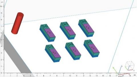
In order to study the build tracks, we built rectangular parallelepiped specimens on which 20 build tracks were made. The specimen is secured to the build platform with supports (blue area on Figure 1). The green area (Figure 1) is the body of the specimen made with the standard manufacturing parameters supplied by SLM Solutions. The body is made up of a rectangular parallelepiped with the following dimensions: length 30 mm – width 10 mm – height 6 mm. On the body of the specimen in the purple area with dimensions: length 20 mm – width 10 mm – thickness 50 µm (one layer), 20 build tracks separated from each other and parallel to the width of the body were created with the various machine parameters shown in Table 2.
The build tracks made in the purple area (one layer) with the machine parameters of Table 2 are examined via micrographic sections in order to measure:
-The width of the track or the melt pool (denoted as w)
-The depth of the track (denoted as d)
-The height of the track (denoted as h)
-The section area of the track (denoted as S)
Figure 2 gives an example showing the identification of the previous measurements and shows the build axis Z.
The section area is obtained with the ImageJ software which automatically detects the outline of the build track on a micrographic section and serves to measure the inner surface of the outline.
In addition to these measurements, we carried out the following:
-A hardness test under low load HV 0.3 in the core of the build track.
-An SEM examination of the track in order to measure the size of the dendrites (estimation of the DAS) using the interception method [9, 10].
Figure 1. Examples of a rectangular parallelepiped specimen: image of a part of the build platform (support plate in blue – body in green – area of build tracks in purple): configurations n°1, 2 and 3
Table 2. Parameters of the 8 different configurations
|
Configuration n° |
Power (W) |
Speed (mm/s) |
|
1 |
350 (version 1.0) |
300 |
|
2 |
350 (version 1.0) |
930 |
|
3 |
350 (version 1.0) |
600 |
|
4 |
550 (version 1.5) |
2750 |
|
5 |
650 (version 1.5) |
2167 |
|
6 |
550 (version 1.5) |
917 |
|
7 |
350 (version 1.0) |
1150 |
|
8 |
650 (version 1.5) |
650 |
Figure 2. A build track: width (w), depth (d) and height (h)
3.1 Preliminary
The main manufacturing parameters with an impact on the build track are traditionally [2-7]:
-The laser power (denoted as P)
-The manufacturing speed: travel of the laser spot (denoted as v)
-The thickness of the deposited powder layer (denoted as e)
-The vector gap: gap between two laser lines (denoted as h)
It is now generally recognized that the energy density is used to optimize the manufacturing parameters. It may be linear, areal or volumetric. In literature, the Eqns. (1-3) are commonly used [11] to define the energy density.
The linear energy density is calculated as follows and is expressed in J/mm:
El=Pv (1)
where, P: power, W; v: manufacturing speed, mm/s.
Likewise, the areal energy density is calculated as follows and is expressed in J/mm²:
Es=Pvh (2)
where, h: hatch spacing (gap between the two laser lines), mm.
And thus, the volumetric energy density is obtained as follows and is expressed in J/mm3:
Ev=Pvhe (3)
where, e: thickness of the powder layer, mm.
The linear energy density is used given that only single tracks are produced in this study as shown in paragraph 2.4. Thus, the build tracks or more specifically the melt pool may be geometrically characterized by its width, depth, height and the section area. Therefore, the linear energy density can be compared with the geometry or the morphology of the single track.
Moreover, the linear energy density can be correlated with the section area of the single track by a simple energy balance [12, 13] as proposed in the Eq. (4).
A(T)El=Sρ(Cps(Tf−Tp)+lf+Cpl(Tmelt pool −Tf)) (4)
where, A(T): absorptivity of the melt pool; El: linear energy density, J/mm; S: section area of the single track or the melt pool, mm²; ρ: density of the material, g/mm3; Cps: specific heat capacity of the material in its solid state, J/(g.K); lf: latent fusion heat of the material, J/g; Cpl: specific heat capacity of the material in the liquid state, J/(g.K); Tf: fusion temperature of the material, K or °C; Tp: temperature of the build platform, K or ℃ (paragraph 2.1).
3.2 Morphology of the single track or the melt pool
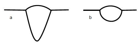
Mauduit et al. [14] report that SLM can operate in two modes: conduction mode or keyhole mode. They add that the keyhole mode is a well-known mode of the high energy welding processes such as electron beam. This mode is characterized by a large depth of penetration which is shown during manufacture by build tracks that are deeper than they are wide – unlike the conduction mode where the build tracks are generally as wide as they are deep, that is to say close to a half disk. Figure 3 shows a schematic representation of a track produced in keyhole mode and a track produced in conduction mode.
Figure 3. a) Track in keyhole mode – b) Track in conduction mode [14]
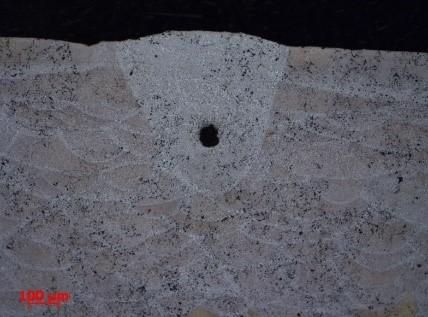
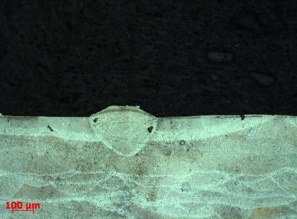
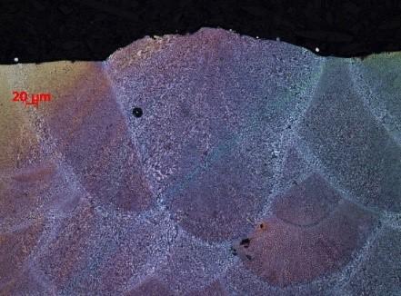
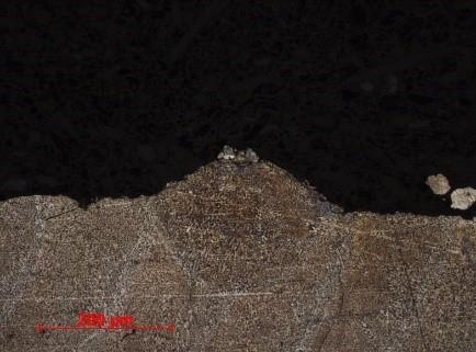
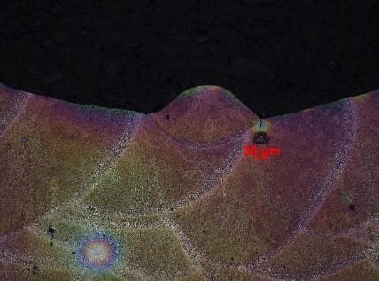
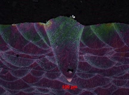
Table 3 shows the optical microscope examinations of the single track produced in the 8 configurations determined in Table 2. Note that the tracks produced with high linear energy densities (typically of around 1 J/mm) exhibit a large and deep shape often with porosity at track root which typically corresponds to the keyhole mode. It is also worth noting that for the lower linear energy densities (of around 0.3 J/mm) tracks featuring shapes similar to a half disk logically correspond to the conduction mode. As regards average linear energy densities (of around 0.6 J/mm), the tracks exhibit shapes between the half disk and large and deep shapes. Therefore, configurations n°1 and 8 can clearly be associated with a keyhole operating mode and configurations n°2, 4, 5 and 7 with a conduction mode.
According to Fujinaga et al. [15], the porosity observed in the tracks in keyhole mode is attributed to the quick closing of the capillary (capillary created during spraying of the material). As the time during which the capillary is filled by the molten material is much longer than the solidification time of the molten material, a porosity is blocked at the track root. This is observed in configurations n°1 and 8. On configuration n°3, a porosity at track toe is also observed and the shape of the track (as that of configuration n°6) tends to resemble that of configurations n°1 and 8. Therefore we can assume that configurations n°3 and 6 are similar to the keyhole mode: in any case, they are no longer in conduction mode.
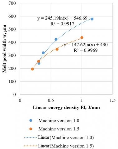
Figure 4 shows that the width of the melt pool (or the single track) increases with the linear energy density, which seems logical, the more energy is provided the larger the weld metal zone. However, it can be noted that two versions of the machine do not give the same change in the width of the single tracks. In each version, the development is perfectly correlated to the linear energy density by a logarithmic function. However, the adjustment parameters of the logarithmic function are different in the two versions. It is surprising to note that it is version 1.0 (with a 400 W laser) that gives the largest single tracks.
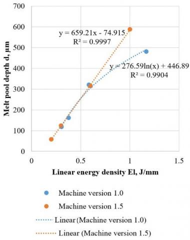
Figure 5 demonstrates that the melt pool depth increases with the linear energy density, which is logical. The more energy provided by the laser, the deeper the single track. However, once again the two machine versions do not give the same correlation. For version 1.0, the depth of the single tracks exhibits a logarithmic evolution with the linear energy density whereas with version 1.5, the evolution is linear. Nonetheless, as opposed to the previous case, it is not version 1.0 which has the largest dimensions but rather version 1.5.
Table 3. Example of the morphology of single tracks depending on the 8 configurations
|
Configuration n° |
El (J/mm) |
Example of build tracks or melt pools |
Configuration n° |
El (J/mm) |
Example of build tracks or melt pools |
|
1 |
1.167 |
5 |
0.3 |
||
|
2 |
0.376 |
6 |
0.6 |
||
|
3 |
0.583 |
7 |
0.304 |
||
|
4 |
0.2 |
8 |
1 |
Figure 4. Evolution of the melt pool width as a function of the linear energy density El
Figure 5. Evolution of the melt pool depth d as a function of the linear energy density El
The reason for the difference in the behavior of the two versions may potentially be due to the size of the laser spot. Indeed, a larger laser spot produces a larger and possibly shallower single track. However, with both versions, we noted a similar or identical spot diameter: approximately 83 to 88 µm. With version 1.5, in addition to the modification of the laser, the gas flows were improved which led to lesser clogging of the manufacturing area. It can be assumed that there is better smoke and slag evacuation with version 1.5 and that the laser is less disturbed by all the particles present in the build area. Therefore, the laser spot shows a stain that is similar to the diameter measured for version 1.5 as it is relatively undisturbed whereas for version 1.0, the spot is more disturbed and features a larger stain than the measured diameter. Indeed, the smoke and particles in the manufacturing area led to a defocusing of the laser spot. This assumption can be used to explain a larger and shallower single track (with the same linear energy density) for version 1.0.
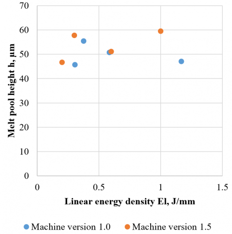
Figure 6 illustrates the changes in the height of the single track as a function of the linear energy density. Note that h is stable for all linear energy density values regardless of the version of the machine. The values of h are approximately 50 µm. It is logical to conclude that the height is directly related to the thickness of the deposited powder layer which is 50 µm (paragraph 2.1).
Figure 6. Evolution of the melt pool height h as a function of the linear energy density El
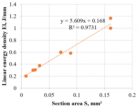
By applying the Eq. (4), it is possible to plot the linear energy density El as a function of the section area of the melt pool. Therefore, based on the Eq. (4), a straight line is obtained (refer to Figure 7). We note a relative scattering of the values for higher linear energy densities.
Figure 7. Evolution of the linear energy density as a function of the section area of the melt pool
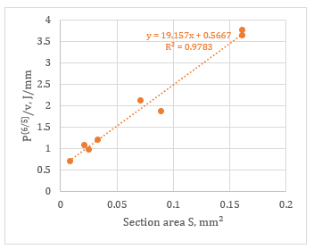
According to Grange et al. [13], this scattering stems from a slight increase of the section area S with the power P, at a fixed linear energy density. Thus, he proposes to plot El P (1/5) i.e. P (6/5)/v as a function of S. This suggests an increase of A(T) with the temperature of the melt pool. Figure 8 shows the changes to Figure 7 with these new conditions. There is a pronounced reduction in the scattering for the high values in P(6/5)/v (therefore, at high linear energy density), however this has slightly degraded the median values of the straight line as can be seen in Figure 8. Nonetheless, there is a slight improvement in the coefficient of determination R².
Figure 8. Linear energy density as a function of the melt pool section area following correction of a power effect for single tracks
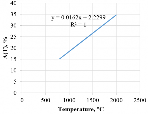
Based on the slope of the linear regression equation in Figure 8, we are able to obtain A(T) as a function of the temperature with the Eq. (4) (Figure 9). For the aluminum alloy AlSi7Mg0.6, we use: ρ = 0.00268 g/mm3 [16]; Cps = 0.963 J/(g.K) [16]; lf = 425 J/g [17]; Cpl = 1,16 J/(g.K) [17]; Tf = 615°C [16]; Tp = 150℃ (paragraph 2.1).
Figure 9. Evolution of the absorption coefficient for aluminum alloy AlSi7Mg0.6 as a function of the temperature
Pierron et al. [18] state that in stabilized keyhole mode, A(T) reaches 70% but that with lower laser powers the keyhole mode is not achieved and thus the mode is the conduction mode. In these conditions, when the aluminum alloy changes to the liquid state, we obtain an absorptivity of approximately 20%. Figure 9 confirms the fact that A(T) is indeed approximately 20% for temperatures of around 1000 to 1400℃ (conduction mode according to Mauduit et al. [14]) and that A(T) increases for keyhole modes.
3.3 Hardness of the single tracks
The hardness or micro hardness of the single tracks is an interesting item of data: therefore, we can directly observe the impact of the manufacturing parameters and consequently the linear energy density on this hardness or micro hardness and possibly on the conventional mechanical characteristics. Figure 10 shows the evolution of the micro hardness HV 0.3 as a function of El only in the case of the machine version 1.0. We notice a decrease in the hardness with the increase of the linear energy density. This phenomenon is due to the fact that with high linear densities, the single track has a coarser structure (paragraph 3.4). Accordingly, the keyhole mode produces less interesting single tracks: they exhibit porosity at the track root and have a lower hardness value in comparison to the conduction mode.
Figure 10. Evolution of the hardness HV 0.3 as a function of the linear energy density
3.4 Microstructure and mechanical properties
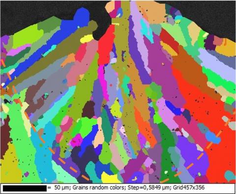
As previously mentioned, the fineness of the single track structure explains the high micro hardness value measured in comparison to an aluminum alloy AlSi7Mg0.6 produced by casting [8, 10]. The microstructure of the as-built aluminum alloy AlSi7Mg0.6 part produced by SLM is described in literature [4, 8, 19]. It is reminded that in the as-built state, the grains in the single track are directed at a right angle to the tangent of the track edge: the grains develop along paths that are orthogonal to the isotherms in accordance with the solidification laws. This is highlighted in Figures 11 and 12 which illustrate the EBSD maps of the single tracks in configurations n°1 – keyhole mode (Figure 11) and n°7 – conduction mode (Figure 12). The edges of the single tracks are identified with a dotted orange curve. In addition, Figure 11 shows porosity at track root with a diameter of approximately 145 µm. This is in line with the observations of paragraph 3.2. concerning the single tracks in keyhole mode. Fine equiaxial grains are also observed at the core of the single tracks; this highlights the internal movements of the melt pool and a disturbed solidification which, like the porosity at the track root, is related to the instability of the keyhole. Conversely, as shown on Figure 12, the single track produced in conduction mode exhibits a properly directed solidification with the grains directed at a right angle to the tangent of the track edge (dotted orange curve).
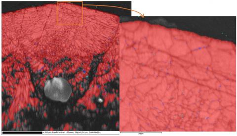
Figure 13 taken from EBSD observations is an overlaying (semi-transparent) of the band contrast serving to examine the grain boundaries and the detected phases. In particular, upon magnification (box in orange), a precipitation at the grain boundaries of the Mg2Si phase (in blue here) and the Al4.5FeSi phase (in turquoise here) can be noted. The aluminum phase is identified in red. Al-Si-Mg type alloys, including AlSi7Mg0.6, exhibit a precipitation sequence which firstly includes the formation of GP-zones (Guinier Preston zones) followed by β’’ and β’ phases (which are responsible for hardening). These are the transition phases towards the Mg2Si equilibrium phase that was detected in the single tracks in configurations n°1 and n°7, primarily at the grain boundary (Figure 13).
Figure 11. Single track, configuration n°1: EBSD map, grain detection
Figure 12. Single track, configuration n°7: EBSD map, grain detection
Figure 13. EBSD observations: band contrast and phases. Red: aluminum – Blue: Mg2Si – Turquoise: Al4.5FeSi
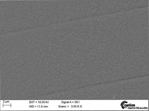
The microstructure is made up of fine dendrites of solid aluminum solution along with eutectic Al-Si (Figures 14) [4, 8, 19]. The fine structure noted is possibly due to an extremely rapid cooling speed [10]. Firstly, we measured the DAS (dendrite arm spacing) as mentioned in paragraph 2.4.2 for configurations n°1, 2, 3 and 7 (machine version 1.0) in the manufacturing plane (X,Y) and in the direction Z (Figures 1 – 2). Figure 14 illustrates the example of the SEM examination of configurations n°1 and 7 in the plane (X,Y). We observed the fine dendrites, however a difference in the size of the dendrites and therefore of the DAS is immediately noted. Configuration n°1 has more energy ( El= 1.167 J/mm) than configuration n°7 ( El = 0.304 J/mm), which is reflected by the size of the dendrites.
(a) Configuration n°1
(b) Configuration n°7
Figure 14. SEM examinations of the dendrites in plane (X,Y)
Figure 15 shows the evolution of the DAS as a function of the linear energy density El, as was previously noted the energy input has a direct impact on the size of the dendrites.
Figure 15. Evolution of the DAS as a function of the linear energy density
A magnification of the DAS and consequently of the dendrites can be seen with the increase of the linear energy density (Figure 15). This is due to the cooling speed. The higher the cooling speed, the finer the structure [10]. For configurations with high linear energy density, this cooling speed is slower: there is more energy and as a result more heat that needs to be evacuated. Conversely, for configurations with lower linear energy density, the cooling speed is quicker: there is less energy and as a result less heat that needs to be evacuated. A difference in the size of the DAS in the plane (X,Y) and in the direction Z is also noted. In addition, the finer the structure, the higher the mechanical characteristics: the Hall-Petch relation associates the size of the DAS with the yield strength (Rp0.2) [20] as follows:
Rp0.2=A+K√DAS (5)
where, A: material flow stress, MPa; K: a constant, MPa√mm.
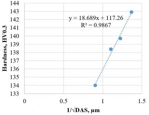
Figure 16 illustrates the Hall-Petch model. We plotted the hardness (representative of mechanical characteristics) as a function of 1/√DAS and we noticed a linear correlation between the two quantities, thereby confirming the Hall-Petch model.
Figure 16. Identification of the Hall-Petch model
It is also noted that the DAS values obtained in the direction Z are systematically higher than those obtained in the plane (X,Y). As we saw ealier, given that the DAS is closely associated with the mechanical characteristics, the difference in DAS along Z and in the plane (X,Y) therefore reflects an anisotropy of the mechanical characteristics including the yield strength. We used the Eq. (5) to study this anisotropy. We obtained:
ΔRp0.2=K(1√DAS2−1√DAS1) (6)
where, DAS1>DAS2, mm; K=8 for aluminum alloys according to [21], MPa√mm.
Mauduit et al. [8] reported that an anisotropy along the Z axis is observed for mechanical properties, especially elongation. However, we note that the yield strength decreased from 284.5 MPa in the plane (X,Y) to 264 MPa along the build axis Z for manufacturing parameters corresponding to configuration n°2 ( El=0.376 J/mm). Thus, we obtain ΔRp0.2= 20.5 MPa. When the equations of the adjustment curves in Figure 15 are used, we obtain for configuration n°2: DAS1=0.73 µm and DAS2=0.64 µm; hence K(1√DAS2−1√DAS1) = 20.1 MPa. We find that the anisotropy observed along the direction Z is perfectly described. For that matter, we can calculate the constant A with the Eq. (5). In the plane (X,Y), we obtain A = -32.1 MPa and in the direction Z, we obtain A=-31.7 MPa. We can consider that A is approximately -32 MPa.
3.5 Thermal analysis and cooling speed
Rosenthal’s analytic heat model [22, 23] can be applied to the SLM process under certain conditions. For reference, in this model, the heat transfers are only governed by conduction. Promoppatum et al. [24] applied this model in the cases of an inconel 718 alloy manufactured by SLM. They stated that the conditions of the Rosenthal model serve to predict a transverse section (at a right angle to the travel of the laser beam) of the semi-circular single track (or melt pool). Therefore, the depth of the melt pool d is half its width w:
w=2d (7)
Using Figure 3 [14], the diagram of the single track in conduction mode is in line with the statement made by Promoppatum et al. Indeed, the diagram describes the section area of the single track as similar to a half disk.
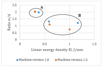
Figure 17 illustrates the w/d ratio as a function of the linear energy density (El). Note that for zone A of the graph the ratio w/d = 2 (or similar). Therefore, for these linear energy densities, the manufacturing mode is the conduction mode and the Rosenthal model applies. For zone B where the w/d ratio is less than 2, the manufacturing mode is the keyhole mode or similar and therefore the Rosenthal model no longer applies.
Figure 17. Keyhole or conduction operating mode as a function of the w/d ratio
The Rosenthal model also serves to estimate an order of magnitude of the cooling speed vcooling upon the solidification of the melt pool [13] (with the correction P(1/5) made to Figure 8):
vcooling =2πkA(T)ElP1/5(Ts−Tp)2 (8)
where, k: thermal conductivity of the material, W/(mm.K) (denoted as 0.152 W/(mm.K) [16]); Ts: solidus temperature of the material, ℃ or K (denoted as 555℃ [16]).
We can also calculate the cooling speed based on the size of the DAS [10, 25] with the following equation:
vcooling =(35DAS)3 (9)
Figure 18 compares the cooling speed obtained by the Rosenthal model (with the correction P(1/5) made to Figure 8) and the size of the DAS. There is a noticeably significant variance between the two curves. The Rosenthal model overestimates the cooling speed which actually ranges between 2.4 104℃/s and 2.8 105℃/s as a function of the linear energy density.
Figure 18. Evolution of the cooling speed as a function of the linear energy density: Rosenthal model – DAS
According to Tang [26], when the operating mode is the conduction mode and therefore the Rosenthal equation applies, it is possible to calculate the maximum temperature achieved in the core of the single track by using the following equation (to which the correction P(1/5) has been added):
Tmelt pool =A(T)ElP1/52.72ρCplS+Tf (10)
where, A(T): absorption coefficient taken equal to 0.2.
Table 4 shows the maximum melt pool temperatures obtained by applying the Eq. (10) to the configurations of zone A of Figure 17. The evaporation temperature of Mg is approximately 1090℃ [27]. Therefore, we note that the temperatures obtained in Table 4 enable the evaporation of the Mg of alloy AlSi7Mg0.6; this confirms the observation made by Mauduit et al. [8] where they noted a loss of approximately 25% in the Mg mass after production.
Table 4. Maximum temperature achieved at the core of the single track in conduction mode
|
Configurations n° |
Maximum temperature |
|
2 |
1497℃ |
|
5 |
1849℃ |
|
7 |
1558℃ |
In general, the Rosenthal model offers a correct representation of the reality however this representation is only valid in conduction mode and even in these conditions the difference between the model and the reality is sometimes significant (example of the cooling speed).
The study demonstrated that the manufacturing parameters have a direct impact on the morphology of the single tracks, i.e. there is an obvious connection between the geometrical dimensions of the single tracks and the manufacturing parameters (power and speed). Likewise, the morphology of the single tracks and therefore the manufacturing parameters have a direct influence on the material microstructure and consequently on the mechanical and other properties of the studied AlSi7Mg0.6 material. This explains the higher mechanical characteristics of the alloy in as-manufactured state (SLM) in comparison to the casting as well as the mechanical anisotropy already observed in literature.
Moreover, the morphology and thermal analysis of the single tracks highlight two operating modes of the laser:
-A keyhole mode characterized by deeper rather than wider single tracks with porosity type defects in the track root and a disturbed solidification. This mode also produces a lower hardness. For these reasons, it should not to be selected for SLM manufacturing.
-A conduction mode characterized by half-disk type single tracks, higher hardness and more suitably directed solidification. This mode also enables a more accurate thermal analysis through the possible application of the Rosenthal model. The conduction mode should be selected for SLM manufacturing.
Additionally, with a simple energy balance, we were able to highlight the relationship between the linear energy density and the morphology of the single tracks as well as understand the absorptivity of the melt pool and its involvement in the Rosenthal model, another interesting parameter.
Furthermore, the thermal analysis by the Rosenthal model can be used to explain the evaporations of Mg which have already been observed in literature on the AlSi7Mg0.6 alloy by calculating the maximum temperatures reached in the single tracks.
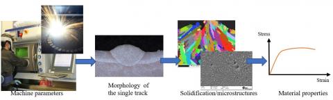
This study sheds light on the connections between the SLM manufacturing parameters, the geometries of the single tracks, the solidification parameters, and the microstructures and properties of the material; all of which is summarized in Figure 19.
Figure 19. Connections between the manufacturing parameters and the material properties – SLM manufacturing
The authors wish to thank CETIM (Centre Technique des Industries de la Mécanique – Technical Centre for the mechanical industries) for the funding and support provided for this study.
[1] Pillot, S. (2016). Fusion laser sélective de lit de poudres métalliques. Technique de l’ingénieur BM7900. https://www.techniques-ingenieur.fr/
[2] Ahmed, A., Wahad, M.S., Raus, A.A., Kamarudin, K., Bakhsh, Q., Ali, D. (2016). Effects of selective laser melting parameters on relative density of AlSi10Mg. International Journal of Engineering and Technology, 8(6): 2552-2557. https://doi.org/10.21817/ijet/2016/v8i6/160806209
[3] Bai, S., Perevoshchikova, N., Sha, Y., Wu, X. (2019). The effects of selective laser melting process parameters on relative density of the AlSi10Mg parts and suitable procedures of the archimedes method. Applied Sciences, 9(3): 583. https://doi.org/10.3390/app9030583
[4] Maamoun, A., Xue, Y., Elbestawi, M., Veldhuis, S. (2018). Effect of selective laser melting process parameters on the quality of Al alloy parts: Powder characterization, density, surface roughness, and dimensional accuracy. Materials, 11(12): 2343. https://doi.org/10.3390/ma11122343
[5] Rao, H., Giet, S., Yang, K., Wu, X., Davies, C.H.J. (2016). The influence of processing parameters on Aluminium alloy A357 manufactured by selective laser melting. Materials & Design, 109: 334-346. https://doi.org/10.1016/j.matdes.2016.07.009
[6] Yang, J., Han, J., Yu, H., Yin, J., Gao, M., Wang, Z., Zeng, X. (2016). Role of molten pool mode on formability, microstructure and mechanical properties of selective laser melted Ti-6Al-4V alloy. Materials & Design, 110: 558-570. https://doi.org/10.1016/j.matdes.2016.08.036
[7] Carter, L.N., Wang, X., Read, N., Khan, R., Aristizabal, M., Essa, K., Attallah, M.M. (2016). Process optimisation of selective laser melting using energy density model for nickel based superalloys. Materials Science and Technology, 1-5. https://doi.org/10.1179/1743284715y.0000000108
[8] Mauduit, A., Gransac, H., Auguste, P., Pillot, S. (2019). Study of AlSi7Mg0.6 alloy by selective laser melting: Mechanical properties, microstructure, heat treatment. Journal of Casting & Materials Engineering, 3(1): 1. https://doi.org/10.7494/jcme.2019.3.1.1
[9] Zhang, B., Garro, M., Tagliano, C. (2003). Dendrite arm spacing in Aluminium alloy cylinder heads produced by gravity semi-permanent mold. Metallurgical Science and Tecnology, 21(1).
[10] Mauduit, A., Pillot, S., Frascati, F. (2015). Application study of AlSi10Mg alloy by selective laser melting: physical and mechanical properties, microstructure, heat treatments and manufacturing of Aluminium metallic matrix composite (MMC). Metallurgical Research & Technology, 112(6): 605. https://doi.org/10.1051/metal/2015039
[11] Aboulkhair, N.T., Simonelli, M., Parry, L., Ashcroft, I., Tuck, C., Hague, R. (2019). 3D printing of aluminium alloys: Additive manufacturing of aluminium alloys using selective laser melting. Progress in Materials Science, 106: 100578. https://doi.org/10.1016/j.pmatsci.2019.100578
[12] Thomas, M., Baxter, G.J., Todd, I. (2016). Normalised model-based processing diagrams for additive layer manufacture of engineering alloys. Acta Materialia, 108: 26-35. https://doi.org/10.1016/j.actamat.2016.02.025
[13] Grange, D., Bartout, J.D., Macquaire, B., Colin, C. (2019). Fusion laser sélective sur lit de poudre: les paramètres de fabrication, un choix clé pour des matériaux performants. Traitements & Matériaux, 458: 37-42. https://www.traitementsetmateriaux.fr
[14] Mauduit, A., Pillot, S., Gransac, H. (2017). Study of the suitability of aluminum alloys for additive manufacturing by laser powder bed fusion. UPB Scientific Bulletin series B, 79(4): 219-238.
[15] Fujinaga, S., Takenaka, H., Narikiyo, T., Katayama, S., Matsunawa, A. (2000). Direct observation of keyhole behaviour during pulse modulated high-power Nd: YAG laser irradiation. Journal of Physics D: Applied Physics, 33(5): 492-497. https://doi.org/10.1088/0022-3727/33/5/304
[16] Davis, J.R., Davis, J.R. (1993). ASM international handbook committee, Aluminum and aluminum alloys. ASM specialty handbook, Materials Park, OH, ASM International, 33.
[17] Mills, K.C. (2002). Recommended values of thermophysical properties for selected commercial alloys. Woodhead Publishing. https://doi.org/10.1533/9781845690144
[18] Pierron, N., Sallamand, P., Matteï, S. (2007). Study of magnesium and aluminum alloys absorption coefficient during Nd: YAG laser interaction. Applied Surface Science, 253(6): 3208-3214. https://doi.org/10.1016/j.apsusc.2006.07.035
[19] Trevisan, F., Calignano, F., Lorusso, M., Pakkanen, J., Ambrosio, E.P., Lombardi, M., Fino, P. (2016). Effects of heat treatments on A357 alloy produced by selective laser melting. In European Congress and Exhibition on Powder Metallurgy. European PM Conference Proceedings, The European Powder Metallurgy Association, pp. 1-6. https://www.researchgate.net/publication/313655604_Effects_Of_Heat_Treatments_On_A357_Alloy_Produced_By_Selective_Laser_Melting
[20] Technique de l’ingénieur M230. CHENAL Bruno. DRIVER Julian. Ecrouissage d’alliages d’aluminium. https://www.techniques-ingenieur.fr/
[21] Murry, G. (2004). Aide-mémoire métallurgie : Métaux – alliages – propriétés,Dunod, Paris.
[22] Rosenthal, D. (1941). Mathematical theory of heat distribution during welding and cutting. Welding Journal, 20: 220-234.
[23] Rosenthal, D. (1946). The theory of moving sources of heat and its application of metal treatments. Transactions of ASME, 68: 849-866.
[24] Promoppatum, P., Yao, S. C., Pistorius, P.C., Rollett, A.D. (2017). A comprehensive comparison of the analytical and numerical prediction of the thermal history and solidification microstructure of inconel 718 products made by laser powder-bed fusion. Engineering, 3(5): 685-694. https://doi.org/10.1016/j.eng.2017.05.023
[25] Colbert, J. (2007). Caractérisation de la fraction solide dans les lopins semi-solides produits par le procédé SEED/. https://doi.org/10.1522/030019065
[26] Tang, M. (2017). Inclusions, porosity, and fatigue of AlSi10Mg parts produced by selective laser melting (Doctoral dissertation, Carnegie Mellon University). https://kilthub.cmu.edu/ndownloader/files/12254540.
[27] Lide, D.R., Baysinger, G., Berger, L.I., Goldberg, R.N., Kehiaian, H.V., Kuchitsu, K., Zwillinger, D. CRC Handbook of Chemistry and Physics. http://analysischamp.com/CRCHandbook01.pdf.