Yagebai Zhao* | Yidian Dong
© 2020 IIETA. This article is published by IIETA and is licensed under the CC BY 4.0 license (http://creativecommons.org/licenses/by/4.0/).
OPEN ACCESS
In reinforced concrete (RC) frame-shear wall structure, the coupling beam needs to yield before the wall limbs are damaged, in order to dissipate the energy of the external load. However, the coupling beam has a limited energy dissipation capacity. Once severely damaged, the coupling beam is difficult to be repaired, which hinders the structural recovery after an earthquake. Considering excellence of metal rubber (MR) in hysteresis energy dissipation and deformation self-reset, this paper changes the energy dissipation mode of the coupling beam by adding an MR damper to the beam. Firstly, the stress-strain curve of MR was obtained through mechanical experiments, and used to construct the constitutive model of the material. Then, the parameters of the damper were designed based on the constitutive model. Next, the MR dampers were installed on the coupling beams of a 12-layer RC frame-shear wall structure. The authors analyzed the time histories of the elastoplastic dynamics of the structure under seismic actions, and calculated the seismic responses like interlayer displacement, absolute acceleration, and base shear force. These parameters were compared with those of the structure without the damper, and the output-deformation envelope curve of the damper on each layer were obtained. In this way, the authors studied how the parameters of the MR damper affect the seismic response of RC frame-shear wall structure. The results show that adding the MR damper to coupling beam can effectively weaken the seismic response of the RC frame-shear wall structure.
metal rubber, constitutive model, damper, coupling beam, seismic response
In ductility-based seismic design, the coupling beam is the main energy dissipator in reinforced concrete (RC) frame-shear wall. Before the wall limbs are damaged, the coupling beam yields and consumes most of the energy. With a small span-depth ratio, the coupling beam often suffers from brittle shear failure. Once severely damaged, the coupling beam is difficult to be repaired, which hinders the structural recovery after an earthquake.
Energy dissipation has been proved to be an effective technique to enhance the seismic resistance of structures. By this technique, an energy dissipator with strong energy-dissipating capacity is added to the target structure. During normal use, the dissipator ensures the lateral stiffness of the structure, and keeps the structure in an elastic state. If a major earthquake occurs, the damping of the energy dissipator will increase with the lateral displacement, which dissipates seismic energy in a concentrated manner and reduces the vibration response of the structure. In this way, the main structure will be protected from seismic damage.
The structural vibration control was conceptualized by American scholar J.T.P. Yao in 1972. Since then, various energy-dissipating and shock-absorbing (EDSA) devices have emerged. Many scholars have explored deep into structural vibration control. Marko et al. [1] of Queensland University of Technology in Australia suggested digging holes at different heights of the shear wall, and install EDSA devices in the holes. Bagheri et al. [2] also proposed to open crenel-shaped vertical seams along the vertical central axis of the shear wall, and deploy vertical EDSA devices in these seams. Park and Yun [3] attempted to improve the energy-dissipating capacity of coupling beam by replacing the beam with mild steel energy-dissipating components. The EDSA devices adopted in the above studies will have irreversible inelastic deformations after an earthquake, and need to be further replaced.
Metal rubber (MR) is an elastic porous material formed by winding thin metal wires into spring coils, followed by weaving and punch molding [4]. This novel material has been widely applied in engineering machinery, military, aerospace, marine, and shipping, thanks to its large damping, light weight, good flexibility, strong capacity of impact energy absorption, high resistance to high or low temperature, and slow aging process. Experimental evidences suggest that the MR, however deformed under external load, can return to the original shape after the load is removed, that is, the material possesses unique super-elasticity and strong capacity of energy dissipation [5-8].
This paper aims to improve the ductility of coupling beam, and give fully play to its energy-dissipating capability. To this end, an EDSA device was designed based on the MR for the coupling beam of RC frame-shear wall structure. The proposed device can fully dissipate seismic energy, control the seismic response of the structure, and automatically return to the original shape after the earthquake, eliminating the need for replacement.
Many experiments have shown that the MR is a nonlinear dry friction damping material with good deformation self-reset ability [9-13]. The material has a double-line functional constitutive relationship (memory resilience). In terms of non-memory resilience, the elastic resilience contains a strong third-order nonlinear term [14]; the damping force mainly encompasses the primary viscous damping term, plus a negligible high-order velocity term. The restoring force of the MR damper is featured by nonlinear hysteresis. The damping components of the damper involve both viscous damping and dry friction damping components [15-17]. These complex factors must be considered in the design of the constitutive model.
Chen et al. [18] described the overall stiffness of the MR with the series and parallel connections of small curved beams, and derived the constitutive relationship through experiments. After repeated experiments, Zhou et al. [19] proposed an experimental method to determine the layup coefficient based on the meso-level constitutive model of combined deformation of micro springs, and then established a constitutive equation containing the meso-structure information of the MR. Ma et al. [20] conducted macro-mechanical analysis on the third-order nonlinear hysteresis functional constitutive relationship between force and displacement of MR vibration isolator. Jiang et al. [21] created the deformation models of MR components through experiments.
In this paper, the constitutive model of the MR is set up through experimental fitting. The least squares (LS) method was adopted to perform piecewise linear fitting on the experimental data, under the principle that equal envelope areas mean equal energies. The Matlab software was selected as the computation platform.
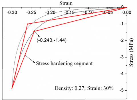
Based on the previous compressive tests on the MR [22], the stress-strain curve of the specimen (temperature: room temperature; loading frequency: 1Hz; relative density: 0.27; maximum strain amplitude: 20%) in the last cycle was divided into a loading segment and an unloading segment. Then, the loading segment was fitted piecewise by the LS method, producing the lines OA and OB in Figure 1. Thus, the initial elastic modulus of the simplified model, the elastic modulus of the strain-hardening segment, the hardening stress, and the hardening strain were determined. Finally, the lines BC and CO were obtained by the said principle, such that the envelope area of the simplified model equals that of the test curve.
Figure 1. The model fitting of strain hardening lines
As shown in Figure 1, the loading and unloading segments are respectively divided into two lines; The stiffness in the second line of the loading phase is greater than the initial loading stiffness, i.e. the initial stiffness of the material.
The constitutive model established by the above method boasts a simple form and clear characteristic parameters in each phase, and thus greatly facilitates the parameter design of any damper based on the MR. The simplified model not only characterizes the strain hardening features of the material, but also agrees with the test curve. The dissipated energy of the model equals that of the test curve, and is easy to calculate.
ABAQUS, as a powerful engineering software for finite-element simulation, provides a solution to various problems, from linear analysis to nonlinear simulation. Therefore, this software was selected to model the target structure.
Figure 2. The plan and rib arrangement of the structure
The target structure is a 12-layer RC frame-shear wall structure. A segment of the double-limb shear wall was selected for research. The total height of the structure is 43.2m, 3.6m per layer. The specific dimensions of the structure are shown in Figures 2(a) and (b).
According to the general decoration conditions, the load on each floor was assumed as constant at 4.0kN/m2. Considering the slope making layer and thermal insulation layer, the load on the roof was treated as constant at 4.5kN/m2. The linear loads of peripheral walls and parapet walls were set to 5.0kN/m. The dead weights of structural beams, columns, and shear wall were calculated based on their cross-sectional dimensions and bulk density of concrete. The live load was uniformly taken as 2.0kN/m2, and the concrete strength of structural members was uniformly treated as C35.
As shown in Figures 2(c) and (d), HPB235 hot-rolled rebars were adopted for the horizontal and vertical rebars of wall panels, and the stirrups of edge members in beams and shear wall. HPB335 hot-rolled rebars were adopted for the longitudinal rebars of edge members in beams and shear wall.
The concrete was simulated by the concrete constitutive model embedded in ABAQUS. The elastic modulus, Poisson’s ratio, and density of concrete were set to E=23,103MPa, μ=0.2, and 2,700kg/m3, respectively.
The RC frame-shear wall structure contains four columns, 12 coupling beams, and a double-limb shear wall. During the finite-element modeling, the beams and edge columns of the shear wall were meshed into C3D84 solid elements, where the rebars were simulated by separation method. The limbs of the shear wall were meshed into S4R shell elements, where the rebars were simulated as an embedded rebar layer. The isotropic hardening two-line model was adopted for the rebars. The hardening features of rebars were derived from the hardened tensile plastic stress-strain curve.
Figure 3 presents the finite-element model of the double-limb shear wall on ABAQUS.
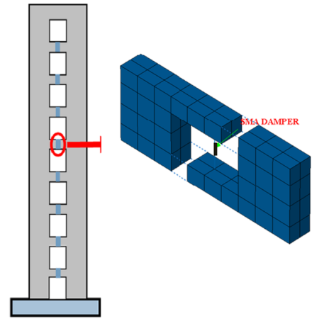
As shown in Figure 4, each MR damper was installed at the middle of a RC coupling beam (i.e. disconnecting the coupling beam vertically in the middle). The MR damper was simulated by the T3D2 elements in the Truss Library.
Based on the user-defined subroutine interface of ABAQUS, the constitutive model of the MR was compiled in Fortran, and embedded in ABAQUS Material Library.
Figure 3. The finite-element model of double-limb shear wall
Figure 4. The location of MR damper in coupling beam
By the constitutive modeling method of the MR, a constative model was fitted according to the test curve of the MR with relative density of 0.27 and strain amplitude of 30% (Figure 5).
Figure 5. The spectrum curves of energy dissipation capacity and elastoplastic demand
After the MR damper had been installed on the coupling beam, the secant stiffness of the constitutive model increased once the MR entered the stress hardening phase, while the output of MR damper started to rose. The ensuing growth in the additional stiffness of the coupling beam caused the overall stiffness of the structure to rise, thereby amplifying the acceleration in seismic response.
To avoid poor control effect, the damper length and area were designed based on the stress and strain, when the maximum strain of the damper arrives at the inflection point between the two lines in the constitutive curve (i.e. the moment before entering the stress hardening segment). Then, the MR damper parameters were configured as σA=1.44MPa and εA=0.243, under the situation that the damper output maximizes when the strain in the constitute model reaches 24.3%.
4.1 Design of damper output and cross-sectional area
When the overall structure yields, the maximum shear force at the end of the coupling beam appears on the right side of the third layer. The freebodycut command in the ABAQUS was called to extract the shear force of 456kN (Figure 6).
Figure 6. The shear force at the beam ends on the third layer
According to the equilibrium conditions, the shear force is numerically equal to the output of the damper, that is, the damper output is 45.6 tons. The cross-sectional area A of the damper can be calculated by:
$A=\frac{F_{D \max }}{\sigma_{24.3 \%}}=\frac{456 \mathrm{KN}}{1.44 \mathrm{MPa}}=0.316 \mathrm{m}^{2}$ (1)
4.2 Design of damper length L
When the overall structure yields, the interlayer displacement peaks on layer 8, i.e. Δfy=3.31mm. Figure 7 shows the geometric relationship between the relative deformation of beam ends and interlayer displacement. It can be seen that this relationship can be described as:
${{\Delta }_{by}}=\frac{{{l}_{c}}}{H}\cdot {{\Delta }_{fy}}$ (2)
where, lc and H are the length and height of the coupling beam, respectively; Δfy is interlayer displacement.
From formula (2), the relative displacement at the beam ends of layer 8 can be obtained as $\Delta_{b y}=\frac{l_{c}}{H} \cdot \Delta_{f y}=2.5 \times 3.31 \mathrm{mm}=8.275 \mathrm{mm}$. Then, the damper length can be derived from this displacement:
$L=\frac{\Delta_{b}}{\varepsilon_{24.3 \%}}=34(\mathrm{mm})$ (3)
Figure 7. The relationship between the relative deformation of beam ends and interlayer displacement
To sum up, the damper parameters were preliminarily determined as length L=34mm, and cross-sectional area A=0.316m2. These parameters were taken as benchmark parameters to design different combinations of characteristic parameters of the damper, analyze the relationship between these parameters and EDSA effect, and identify the most reasonable damper design.
4.3 Definition of characteristic parameters
In the EDSA structure of the coupling beam, the damper must yield before the beam to dissipate energy. Therefore, the yield force ratio of damper to beam end (the most unfavorable part of the beam) was considered a characteristic parameter of the damper.
Since the MR damper should act as the main dissipator of seismic energy, the damper on the coupling beam must yield before the wall limbs to dissipate energy. Hence, the yield displacement ratio of damper to wall limbs was selected as the other characteristic parameter of the damper.
(1) Yield force ratio Γ
According to the stress hardening constitutive model of the MR, σA=1.44MPa and εA=0.243 at the first strain hardening point. The damper parameters were configured under the conditions of this point. The yield force ratio can be defined as:
$\Gamma =\frac{{{F}_{str}}}{{{F}_{dam}}}=\frac{{{F}_{str}}}{{{\sigma }_{A}}.A}$ (4)
where, Fstr=456kN is the maximum beam-end shear force obtained by the Pushover method when the structure yields; Fdam is the damper output.
(2) Yield displacement ratio Δ
$\Delta =\frac{{{\Delta }_{str}}}{{{\Delta }_{dam}}}=\frac{{{\Delta }_{str}}}{{{\varepsilon }_{A}}.L}$ (5)
where, Δstr is the beam-end relative displacement derived from geometric relationship; Δdam is damper deformation.
Then, two yield force ratios (0.5 and 1) were designed based on the beam-end shear force on the layer with the maximum interlayer displacement, when the structure yields; two yield displacement ratios (0.6 and 1) were designed based on the vertical displacements at the middle of the coupling beam when the wall limbs yield. The four parameters were grouped into four parameter combinations. The damper area and length corresponding to each combination is presented in Table 1.
Table 1. The parameter designs of MR damper
|
|
Δ=1.0 |
Δ=0.6 |
|
Γ=1.0 |
A=0.316m2, L=34mm (Kd=0.55×10⁵N/mm) |
A=0.316m2, L=56mm (Kd =0.335×10⁵N/mm) |
|
Γ=0.5 |
A=0.632m2, L=34mm (Kd =1.12×10⁵N/mm) |
A=0.632m2, L=56mm (Kd =0.669×10⁵N/mm) |
Note: A, L, and Kd are the area, length, and initial stiffness of the damper, respectively.
The seismic responses of the structure with damper (controlled model) and that without damper (uncontrolled model) were compared under the action of Chi-Chi seismic wave, whose peak acceleration was 400Gal.
5.1 Interlayer displacement and acceleration
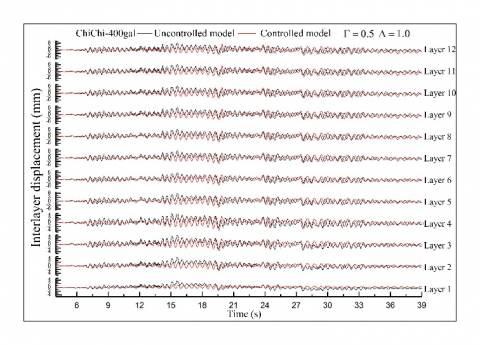
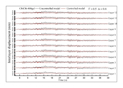
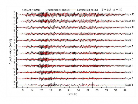
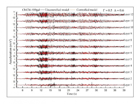
Figures 8(a)-(d) compare the interlayer displacements and absolute accelerations of the dampers with different parameter combinations. All the four dampers achieved satisfactory EDSA effect: the interlayer displacement was effectively controlled except for t=27-33s; the absolute acceleration of each layer was controlled well except for t=24-28s.
(a)
(b)
(c)
(d)
Figure 8. The time histories of interlayer displacement and acceleration under different parameter combinations (ChiChi-400gal)
Figure 9 presents the distribution curves of interlayer displacements and peak accelerations across the layers. Under rare earthquakes, when the yield force ratio was the same (Γ=0.5), the parameter combination with relatively large yield displacement ratio (Δ=1) had relatively small interlayer displacement, and relatively good control effect. The controlled models could not control the absolute acceleration well under major earthquakes; the peak acceleration did not change greatly with the yield force ratio or yield displacement ratio. When the force ratio was the same, the parameter combination with relatively small yield displacement ratio (Δ=0.6) had relatively good control effect on acceleration.
(a)
(b)
Figure 9. The curves of interlayer displacement and peak acceleration (ChiChi-400gal)
5.2 Damper output and deformation
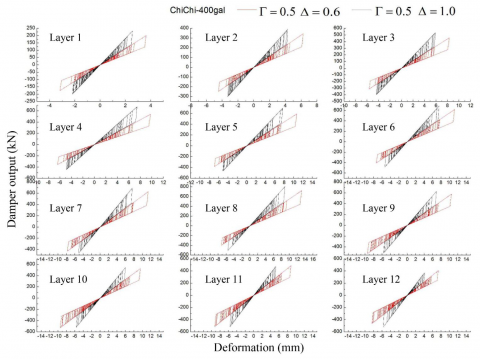
Figure 10 compares the damper output-deformation curves of the uncontrolled models with two parameter combinations, namely, Γ=0.5, Δ=0.6 and Γ=0.5, Δ=1. It can be seen that the damper output-deformation hysteresis curves were of the same shape as the established constitutive model. On all 12 layers, none of the damper output-deformation curves entered the stiffness hardening segment. This reduces the additional stiffness brought by the damper to the entire structure, promoting the control effect on acceleration.
The hysteresis curves of the dampers only covered a part of the ideal hysteresis curve. Therefore, the energy dissipation capability of the dampers was not fully exerted. The relatively large damper outputs appeared on layers 6-9, peaking on layer 8 (800kN).
Comparing the damper outputs and deformations of the two parameter combinations, the damper deformation was greater under Γ=0.5, Δ=0.6, because the damper is longer than that under the other combination. Hence, it is preliminarily concluded that: with the same material and area, the damper length is negatively correlated with stiffness, and positively with damper deformation.
Figure 10. The damper output-deformation curves
5.3 Base shear
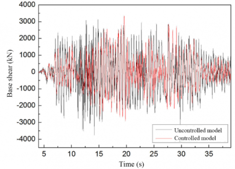
Figure 11 compares the time histories of the base shears before and after damper installation.
Figure 11. The base shears before and after damper installation
Before the damper was installed, the maximum base shear was 3,650kN; after damper installation, the maximum base shear was 3,300kN. Hence, the base shear of the structure was not ideally controlled by installing 12 dampers to the coupling beams.
This paper installs MR dampers with self-reset function at the middle of coupling beams in RC frame-shear wall structure, and analyzes the time histories of the nonlinear dynamics of a 12-layer structure with these dampers. By comparing the controlled and uncontrolled models, different combinations of characteristic parameters of the damper were compared in the control effect of the seismic response of the structure. The main conclusions are as follows:
(1) The MR damper can yield due to the vertical relative displacement, induced by the bending of wall limbs, at the middle of the disconnected coupling beam, and thereby dissipate the seismic energy. The addition of MR dampers can control the seismic responses (interlayer displacement and absolute acceleration) of the structure to a certain extent.
(2) Under the same yield force ratio, the damper stiffness increases with the characteristic parameter of interlayer displacement Δ. The higher the stiffness, the better the control of interlayer displacement. Under the same yield displacement ratio, the control effect on seismic response increases with the decline of the yield force ratio.
(3) The relatively large damper outputs appeared on layers 6-9, peaking on layer 8 (800kN). Comparing the damper outputs and deformations of the two parameter combinations, the damper deformation was greater under Γ=0.5, Δ=0.6.
(4) The base shear of the structure was not ideally controlled by installing 12 dampers to the coupling beams.
This work is supported by Heilongjiang Provincial Natural Science Foundation for the general project “Seismic Failure Modes of Frame-Shear Structures in Energy Dissipators Based on Metal Pseudo-Rubber/ Silicone Rubber” (Grant No.: E201401).
[1] Marko, J., Thambiratnam, D., Perera, N. (2004). Influence of damping systems on building structures subject to seismic effects. Engineering Structures, 26(13): 1939-1956. https://doi.org/10.1016/j.engstruct.2004.07.008
[2] Bagheri, B., Oh, S.H., Shin, S.H. (2018). Distribution of optimum yield-strength and plastic strain energy prediction of hysteretic dampers in coupled shear wall buildings. International Journal of Steel Structures, 18(4): 1107-1124. https://doi.org/10.1007/s13296-018-0098-7
[3] Park, W.S., Yun, H.D. (2006). Seismic behaviour and design of steel coupling beams in a hybrid coupled shear wall systems. Nuclear Engineering and Design, 236(23): 2474-2484. https://doi.org/10.1016/j.nucengdes.2006.03.008
[4] Yu, W., Zhijun, L., Baolin, L., Mingshuai, G. (2014). Stiffness characteristic comparison between metal-rubber and rubber isolator under sonic vibration. Journal of Vibroengineering, 16(2): 645-655. https://www.jvejournals.com/article/14743
[5] Wu, R.P., Bai, H.B., Lu, C.H. (2018). Analysis of radial compressive properties and mechanical model for ring metal rubber. Mechanical Science and Technology for Aerospace Engineering, 37(4): 635-640. https://doi.org/10.13433/j.cnki.1003-8728.2018.0422
[6] Ren, Z.Y., Chen, Q., Bai, H., Wu, Y. (2018). Study on damping energy dissipation characteristics of cylindrical metal rubber in nonforming direction. Advances in Materials Science and Engineering, 1-10. https://doi.org/10.1155/2018/5014789
[7] Senthil, M.S., Noorul, H.A., Sathiya, P. (2020). Eco-friendly frictional joining of AA6063 and AISI304L dissimilar metals and characterisation of bimetal joints. Journal of New Materials for Electrochemical Systems, 23(2): 101-111. https://doi.org/10.14447/jnmes.v23i2.a07
[8] Li, J., Liang, L., Liu, X., Ma, H., Song, J., Wei, Y. (2018). Experimental studies on strengthening and failure mechanism for the metal/silicone rubber/metal bonding system. International Journal of Applied Mechanics, 10(3): 1850029. https://doi.org/10.1142/S1758825118500291
[9] Omarov, K.M., Abakarov, A.D. (2018). The seismic response investigation on the multi-storey buildings with seismically insulating rubber-metal supports. In Materials Science Forum, 931: 362-367. https://doi.org/10.4028/www.scientific.net/MSF.931.362
[10] Ao, H., Jiang, H., Ulanov, A.M. (2005). Dry friction damping characteristics of a metallic rubber isolator under two-dimensional loading processes. Modelling and Simulation in Materials Science and Engineering, 13(4): 609. https://doi.org/10.1088/0965-0393/13/4/011
[11] Ulanov, A.M., Bezborodov, S.A. (2014). Life-time of vibration insulators made of metal rubber material under random load. Research Journal of Applied Sciences, 9(10): 664-668. https://doi.org/10.3923/rjasci.2014.664.668
[12] Srinivasan, V.P., Palani, P.K. (2019). Experimental investigation on wire-electro discharge machining of tungsten carbide (WC) using response surface methodology (RSM). Journal of New Materials for Electrochemical Systems, 22(3): 155-158. https://doi.org/10.14447/jnmes.v22i3.a07
[13] Ponomarev, Y.K. (2014). On transformation of hysteresis in damper rings made of "metal rubber" pressure-tested wire material under precessional loading conditions. ARPN Journal of Engineering and Applied Sciences, 9(10): 1866-1872.
[14] Troynikov, A.A., Moskalev, Y.A. (2014). Elastic and strength properties of metal rubber material. International Journal of Engineering and Technology, 6(5): 2276-2282.
[15] Ponomarev, Y.K., Ermakov, A.I., Simakov, O.B., Mikhalkin, I.K. (2013). Metallic counterpart of rubber: A material for vibration and shock protection. Metal Science and Heat Treatment, 55(1-2): 8-13. https://doi.org/10.1007/s11041-013-9570-3
[16] Ao, H., Jiang, H., Wang, S., Xia, Y., Ulanov, A.M. (2003). Dry friction damping characteristics of metallic rubber (MR) isolator with 2-D loading process (No. 2003-01-1470). SAE Technical Paper. https://doi.org/10.4271/2003-01-1470
[17] Ao, H.R., Jiang, H.Y., Yan, H., Xia, Y.H., Ulanov, A.M. (2005). Research of a metal rubber isolation system based on complex stiffness. Journal of Harbin Institute of Technology, 37(12): 1615-1617. https://doi.org/10.3321/j.issn:0367-6234.2005.12.005
[18] Chen, Y.Q., Guo, B.T., Zhu, Z.G. (2002). The investigation of the stiffness characteristics and the stress-strain relation of metal rubber. Journal of Aerospace Power, 17(4): 416-420. https://doi.org/10.3969/j.issn.1005-2550.2018.04.013
[19] Zhou, Z., Wu, J.H., Liang, X., Lin, M., Yuan, X.Y. (2019). Quantitative study on energy dissipation mechanism of metal rubber by an enhanced turbulence model. Modern Physics Letters B, 33(33): 1950413. https://doi.org/10.1142/S021798491950413X
[20] Ma, Y., Zhang, Q., Zhang, D., Scarpa, F., Liu, B., Hong, J. (2015). The mechanics of shape memory alloy metal rubber. Acta Materialia, 96: 89-100. https://doi.org/10.1016/j.actamat.2015.05.031
[21] Jiang, H.Y., Ao, H.R., Xia, Y.H., Sun, Y., Ulanov, A.M. (2002). An experimental modeling method for the analysis of metal-rubber isolator system. Journal of Experiment Mechanics, 17(3): 363-368. https://doi.org/10.3969/j.issn.1001-4888.2002.03.019
[22] Zhao, Y.G.B., Ding, P.Z., Zhao, Y., Yan, X.W. (2019). Mechanical properties of metallic pseudo rubber-silicon rubber composite for three-way seismic isolation. Revue des Composites et des Matériaux Avancés, 29(6): 341-350. https://doi.org/10.18280/rcma.290601