Souad Benarrache* | Toufik Benchatti | Hadj Aissa Benhorma
OPEN ACCESS
Welding assembly of steels HSLA (High Limit of Elasticity) occupies an important place in the mechanical industry and in the shaping industry of transport facilities, hydrocarbon storage and other industries. X70 steels have a very important place in the mechanical industry, naval and oil industry. Also, were interested by studying the effect of heat treatments (energy supply) on structural stability (formation and dissolution of carbides and nitrides) in the weld bead zones of X70 steel and the zones adjacent areas (HAZ and During welding, the weld bead undergone very large temperature variations until melting followed by a more or less rapid solidification (out of equilibrium thermodynamic state), which causes an evolution of the microstructure during application of heat treatments (supply energy), which subsequently affects the mechanical properties and / or the electrochemical behavior (corrosion).The type of heat treatment influences the diffusion and backscatter of the addition elements with respect to the formation of carbides and nitrides in the microstructure of the weld beads.
HSLA steels, X70, seam, weld metal zone WMZ, the heat affected zone HAZ, X-ray diffraction, carbide and nitride, diffusion, backscatter
The technological development, and the mastery of getting steel of good mechanical and structural quality contributed to the based steel structure and installations, of very high performances particularity on the mechanical plans resistance to corrosion etc. Welding steels has a lot of advantage in the industry and the shaping of the installations. But it also has disadvantages and weak points, which round the assembly vulnerable. The fused area of the weld and the heat affected zone HAZ, do not have the same structural characteristics and mechanical characteristics comparable to the base metal zone.
Heat treatments have a remarkable effect on the formation and dissolution of carbides and nitrites in the weld bead area of X70 steel. Which therefore, make the weld bead under high internal mechanical stress. Energy in the form of controlled heat treatments, leads to thermodynamically stable systems, by the formation or dissolution of the different phases which is accompanied by the dissipation of internal stresses, the is latter initially introduced by cooling effect, more or less rapid to free air, of the weld bead (non-equilibrium state).
Monitoring the evolution of the microstructure by optical microscopy, X-ray diffraction and measurement of hardness of the different zones of the weld seam (Weld metal zone WM and the heat affected zone HAZ). According to each heat treatment applied to it, shown the coupling of the structural morphology, microstructure and dissipation (relaxation) of internal stresses.
The research on the fragility and safety of steels, has led to the appearance on the market of a relatively large number of steels for the manufacturing of large diameter pipes. The main concerns with the introduction of alloying elements into steels are related to the increase in mechanical characteristics (elastic resistance Er, maximum resistance Mr), the easiest material implementation possible (welding) and severe conditions of use (high operating pressure, corrosive environment) [1].
Ferrite-hardening additive elements are distinguished. The most effective elements are those that we try to reduce for weldability reasons (carbon) or improvement of the resilience characteristics (phosphorus, carbon, ... etc.).
One of the methods of obtaining a combination of high strength, good ductility and weldability of steels is the refinement of ferritic grain.
The interest of fine grain in high yield strength steels ferrite-pearlite structure is therefore double, the interest of fine grains in high yield strength steels with a ferrite-pearlite structure is therefore twofold, hence the interest in the addition of elements allowing the refining of the ferritic grain [2], hence the starting grain austenitic. Grain refining is achieved by the addition of elements forming fine precipitates, which through their interaction with austenitic grain boundaries, prevent the development of these [3]. The factors involved in the grain refining process are: alloy elements that can form fine precipitates. The most used are (Al, Nb, Ti) forming nitrides or carbonitrides, acting according to their contents as well as the contents of N and C and the heat treatment carried out.
The precipitation, in the form of fine nitrides, occurs either during rolling or during heating before normalization in the range [600-700 °C] [4]. Because of the diffusion processes that lead to the coalescence of the AlN precipitates, and then to their dissolution [5], the austenitic grain will no longer vary, whereas according to the temperature and time parameters [6] In the case of niobium, the precipitates formed are carbonitrides Nb (Cx, Ny), the contents of C and N depend on the composition and temperature. The cooling precipitation coincides with the γ-α transformation, while the precipitation during heating is in temperature the range [600-700 °C] [7].
Niobium can exert a strong effect on the refining of the grain like aluminum, and the critical particle size is about 300 Å as for AlN. Finally, only the simultaneous addition of Al and Nb is slightly more effective than that of Al alone [4. 7. 9.16].
Titanium forms two compounds. On the one hand, TiN which is an extremely stable precipitate, practically insoluble in austenite [2.13.14], and on the other hand a TiC carbide. Titanium not trapped by nitrogen forms a carbon-rich carbonitride of diameter about 200 Å, which dissolves in the austenite up to about 1300 °C. This "carbide" is responsible for controlling the growth of the γ grain.
The addition of one or more elements such as Al, Nb and Ti in order to refine the grain and improve the characteristics of the steels is therefore essential.
The study of the effect of heat treatments on the dissolution and formation of carbide and weld-wire nitride of pipeline steels requires metallographic examination to characterize the morphology of the microstructure, accompanied by XRD analyzes for structural characterization according to the application of a series of heat treatments on the steel in question.
The materials studied and a high yield strength steel X70 (industrial pipeline used by SONATRAGH Algeria), the latter this classifies in API standard 5L5L (American Petroleum Institute Specify for Pipeline) [8].
Table 1 presents the chemical composition of the X70 steel chemical analysis was performed by computer-assisted optical emission spectrometry type ARL-3460 (ANABA).
Table 1. Chemical composition of the steels studied
|
Elements %10-3 |
c |
Mn |
Si |
P |
S |
Cr |
Ni |
Cu |
Mo |
V |
Al |
Ti |
Nb |
Sn |
B |
W |
|
X70 |
83 |
1530 |
9 |
10 |
1 |
30 |
11 |
10 |
2 |
33 |
32 |
16 |
66 |
16 |
3 |
2 |
A heat treatment protocol was carried out for different samples at the mechanical laboratory at the University Laghouat in a VECSTAR LDT furnace. The samples were subjected to a homogenization treatment and relaxation different temperatures from 450 °C, 500 °C, 550 °C, 600 °C to 650 °C for duration of 2 hours respectively (See Figure 1).
3.2 X-ray diffraction
The diffraction measurements were carried out by means of a beam X-ray diffractometer X-Phillips (Holand). The X-ray are generated by a Cu anode kα=1.54060 A°. The operating parameters for all the samples are 40 kV and 50 mA with a step of 0.02° and a fixation time of 1 second for each step. The scanning is carried out over a range 2θ of (20 ° -130 °) with rotation by time of 1 H30.
3.3 Microscopy
The aim of the metallographic examination was to characterize the structural morphology of the steel; in our case it was to highlight the limitation of the zones (weld metal and HAZ) as well as the state of the homogenization, the observation was carried out MEIJI TECHNO CO LTD microscope (China).
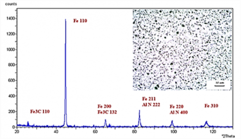
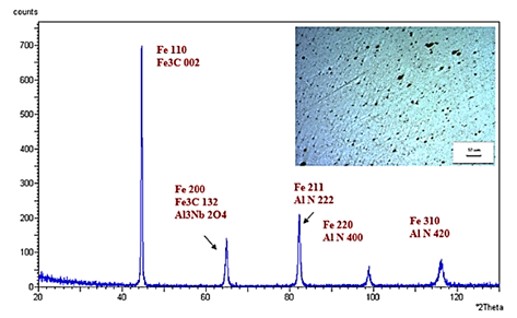
On Figure 2 on represented diffractogram and micrography of the X 70 steel weld seam. On the micrograph of Figure 2, the steel has a homogeneous distribution of the different phases, which are evidenced by the X-ray diffraction (such as Fe matrix, Fe3C cementite and AlN phase).
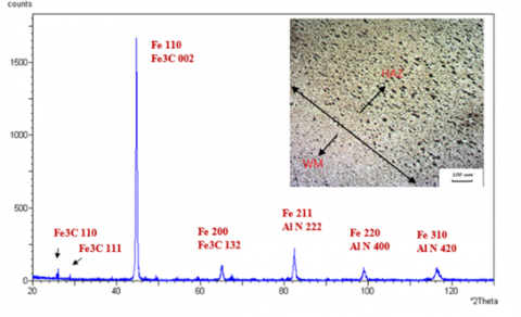
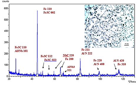
The diffractogram in question, presents the matrix Fe, whose families of the diffracting planes are, (110), (200), (211), (220) and (310), in which the cementite bathes, whose families diffractive planes are, (110), (111), (002), (132) and (310) and the aluminum nitride phase AlN (222) (400) and (420); the latter is very difficult to observe by micrography (very small quantity), from which we can say that our steel has a spherical pearlite ferritic structure. The micrograph and the diffractogram of this zone Figure 3, presents a border zone between the weld seam (molten metal) and the HAZ (heat affected zone) as shown by the indications on the micrograph. A clear variation in the density of spherulite repetitions of perlite (Fe-Fe3C) is clearly observed with a difference in grain size between the two sectors of the micrograph. While from the point of view of the co-existing phases, one notices, compared to the weld metal zone WM it is the same phases
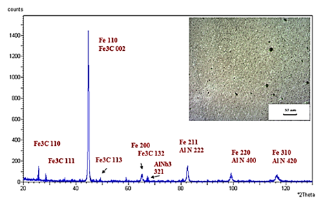
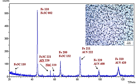
On the optical micrograph of the HAZ Figure 4, we observe a homogeneous distribution of the microstructure (the perlite spherulite) which is fine even at medium magnification, as the X-ray diffraction diffractogram clearly shows, presence of AlN phases, AlNb3.
Figure 2. X70 steel weld seam diffractogram and micrographic observation without heat treatment (raw state)
Figure 3. Diffractogram of the WM and HAZ frontier zone of X70 steel and micrographic observation without heat treatment (raw state)
Figure 4. Diffractogram of the HAZ of X70 steel and micrographic observation without heat treatment (raw state)
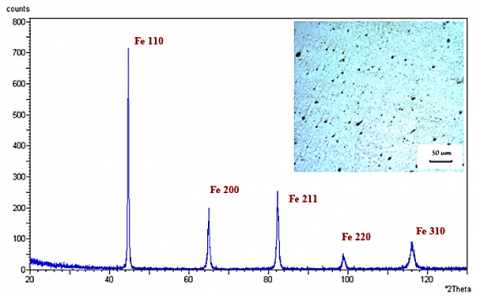
A series of X-ray diffraction and micrographs analysis was performed on all the samples that were subjected to heat treatments according to the selected heat treatment protocol. Figure 5 shows the diffractogram and the micrograph of the weld metal zone samples (WM) and undergoes a heat treatment of 450 °C for a holding time of 2 hours.
X-ray diffraction analysis shows the presence of the two Fe and Fe 3C (matrix) phases by the reflection of the (110), (200), (211), (220) and (310) planes of Fe and (132). Fe3C while noticing that the planes (110), (111) of the cementite are embedded in the background noise of the diagram. The analysis of the micrograph shows a homogeneous morphology of the structure with a small amount of perlite spherulites.
The application of heat treatments on samples of the weld seam, by varying the heat treatment temperature of 550 °C, 650 °C significantly alter the morphology and microstructure of the X70 steel.
The diffractograms of the different zones WM and HAZ '' Figure 5, Figure 6, Figure 7 and Figure 8, show well the presence of new phase such as NbC, Al3Nb. With an evolution of the morphology and a distribution of spherulites’ of perlite and an appearance of Nb carbide and Ti carbide precipitates by the reflection of the different families of crystallographic TiC planes, and those of NbC.
Figure 5. Diffractogram of the WM of the weld seam and micrographic observation (under 450 °C heat treatment for a holding time of 2 hours)
Figure 6. Diffractogram of the HAZ of the weld seam and micrographic observation (under heat treatment 450 °C for a 2 hour hold time)
Figure 7. Diffractogram of the WM of the weld seam and micrographic observation (under heat treatment 550 °C for a holding time 2 hours)
Figure 8. Diffractogram of the HAZ of the weld seam and the micrographic observation (under heat treatment 550 °C for a holding time 2 hours)
Figure 9. Diffractogram of the weld metal WM and micrographic observation (under heat treatment 650 °C for a holding time of 2 hours)
Figure 10. Diffractogram of the HAZ zone of the weld seam and the micrographic observation (under 650 °C heat treatment for a holding time of 2 hours)
After the various heat treatments, applying the X-ray diffraction analysis of the sample from the zone between the melted zone and the thermally affected zone shows an evolution of the microstructure by the appearance of the new phases.
The diffractograms and micrographs of samples from the HAZ zone and after heat treatment at 450 °C and 550 °C for two hours of maintenance, the co-existing phases in the steel are Fe (matrix), Fe3C, AlN, Al 3Nb whose reflective planes are shown in Figure 6, Figure 8 and Figure 10, Al 3Nb, AlN, Fe3C and Fe (the matrix). The micrograph of the treatments (450 °C, 550 °C) shows an increase in grain sizes with a more or less homogeneous distribution of perlite. Subsequently and at 550 °C and for 2 hours of maintenance, the same phases exist without change, but with a quantity of Al3Nb which increases, as shown by the peak of the diffraction of Figure 7 (plan reflector (101) of Al3Nb). An apparition of families of Fe3C phase planes that reflect (110), (002), (112) and (023) as well as the NbC, AlNb3 and AlN phases. After a heat treatment at 650 °C for two hours, the diffractogram of Figure 10 clearly shows the reappearance of the NbC phase by the reflection of the families of the planes (220).
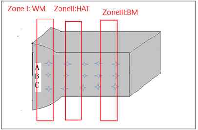
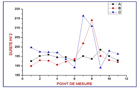
Figure 11 displays the hardness measurements; its purpose is to compare the hardness variation by zone and by profile according to the heat treatment protocol. The zones are defined as follows:
Zone I: WM Weld metal or the zone of connections.
Zone II: HAZ heat affected zone.
Zone III: MB base metal area.
Figure 11. Hardness measurement diagram
The Figure 11 shows the hardness measurements of the three parts A, B and C according to the profile of the sample (reference sample) at different points and part.
Point A has the inner part of the weld.
Point B presents the central part of the weld.
Point C presents the outer part of the weld.
The hardness measurement of the reference sample Figure 12 shows a fluctuation of the hardness HV2 (200HV) with an increase in hardness in the weld bead zone (218HV). Internal part of the weld, a stability of the hardness all along the sample with a decrease in the heat-affected zone HAZ, the point C presents the external part of the weld. But for the other two zones it keeps the same pace, a hardness stability in the base metal zone with a small decrease in hardness in the HAZ and an increase in the weld seam area.
Figure 12. Hardness measurement for the reference sample (without heat treatment)
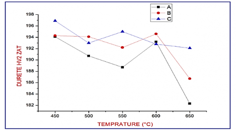
It was observed a stability hardness values of two points A and B with a hardness a value of 190HV of the zone of weld metal (WM), for the internal part C of welding an increase in hardness just value exceeds 240HV Figure 13 shows a variation of the hardness value for each heat treatment, with an increase and a decrease in the latter according to the heat treatment. In Figures 13,14 and 15 measurements of the hardness and carried out in the different zones (the weld melted zone, the thermally affected zone and the base metal) and has different parts always remarks that the hardness of the internal part (point C) and higher than that two points A and B in all zones.
Figure 13. Hardness measurement for different 2H hold time heat treatments for the WM zone (weld metal)
Figure 14. Hardness measurement for different 2H holding time heat treatments for the HAZ zone (heat affected zone)
Figure 15. Hardness measurement for different heat treatments with holding time 2H for zone BM (base metal)
After making a weld seam on X70 steel, its microstructure varies significantly from one zone to another (the weld metal, the heat affected zone), according to the diffractograms of the two zones in the raw state (without heat treatment). It is noted that the microstructure is unchanged by the existence of the same phases, Fe matrix, Fe3C cementite and AlN phase; with the appearance of the precipitates, during welding of the tubes, in the zone of the weld seam and the zone of connection (zone WM, HAZ), whereas the morphology of the micrographs changes a point of view of dissolution and formation by backscattering of the carbides and nitrides.
While at 550 °C, there is a variation in morphology by an increase in spherulites. This increase is explained by a gain in energy (heat input) which directs the system (the matrix and addition elements) towards a thermodynamic equilibrium. This one is strongly affected by the addition elements and the energies of the point and linear defects (internal stresses) as well as the inter-facial tensions between the grains; which changes according to the size of the grains in this system one can illustrate the thermodynamic equilibrium by the equation of the free enthalpy.
$G=\Delta H-T\Delta S+\sum\nolimits_{i}^{n}{Qi}$ (1)
At temperatures T the system balances, when $\frac{\partial G}{\partial T}=0$.
Qi: All the energies of the point and linear defects (internal stresses) as well as the inter-facial tensions between the grains and the dislocations.
In all the diffractograms, following the temperature variations of the heat treatments (450 °C, 550 °C and 650 °C) in the different zones of the weld bead, we notice the existence or not of the carbide and nitride (the phases AlN, Al3Nb, AlNb3, NbC and TiC), their densities in terms of (dispersion) and grain size, this depends on the backscattering of the addition elements or the diffusion of the latter in the Fe matrix.
Figure 12 presents a fluctuation of the hardness measurements, shows well and a high peak on the melted zone of the weld seam whose values are 215HV, 212HV and 210HV, in this zone which are much larger than those of the rest of the other areas.
We notice that even in the melted zone there is variation, which is explained by the rapid mode of cooling, in the high zone of the cord (quenching with the area) and this in parts C and B Figure13; while in the A part (lower part of the bead), the value of the hardness HV (194HV) is much lower than that of the part C and B. This difference in value of hardness is due to the heating of the zone A during different welding passage, we can say that the zone A becomes the thermally affected zone HAZ with respect to the zones C and B.
The variation curves of the HV hardness measurements as a function of the heat treatments of all the zones (weld metal, the thermally affected zone HAZ and base metal) present more or less the same aspects with fluctuations by increase or decrease of the hardness values.
We can also say that the fluctuations are dependent on the dissipation of dislocations (internal stresses) which have a very significant effect on hardness measurements and the Young's modulus. it can be interpreted by the mobility velocity of dislocations low:
$V=\alpha \exp (-\Delta {{H}_{i}})/RT$ (2)
V: speed of mobility of dislocations.
∆Hi: Enthalpy of activation of a dislocation at temperature T.
This speed of dissipation and is measure a purs grains
(Exp: Fe) in our case this velocity will depend enormously on the impurities in the grains namely the existence of the addition elements in gap or carbides by a zone of the matrix.
Following the application of a previously defined heat treatment protocol, the optical microscopy analysis of the morphology and that by x-ray diffraction of the microstructure, of the different zones of the weld seam of the X70 steel, have showed a clear variation of the microstructure by formation and / or dissolution of carbides and nitrides according to the type of heat treatment applied.
The stripping of all the diffractograms, informs us well on the formation and the dissolution of the different phases which can coexist, following a defined heat treatment. For example, one can quote the made of the TiC and NbC phases which form at 650 °C. for a hold time of two hours, whereas at 550 °C. These precipitates dissolve; and that the AlNb3 phase is formed by backscattering effect of the Nb and Al element in solution in the matrix.
Supplied energy in the form of controlled heat treatments leads to thermodynamically stable systems along the formation and / or dissolution of the phases, which is accompanied by the dissipation of internal stresses, initially introduced by the effect of cooling less or slower of the weld seam. The dissipation of internal stresses (dislocations in the grains or inter granular) which is accompanied with the formation and / or dissolution of carbides and nitrides leads to fluctuations in hardness measurements of X70 steel.
|
HSLA |
High Limit of Elasticity |
|
WMZ |
weld metal zone |
|
HAZ |
heat affected zone |
|
MB |
Metal base |
|
XRD |
X-ray diffraction |
|
Mr |
maximum resistance |
|
Er |
elastic resistance |
|
Al |
Aluminum |
|
Nb |
Niobium |
|
Ti |
Titanium |
|
C |
Carbide. |
|
NC |
Carbonitride |
|
V |
Vanadium |
|
Fe3C |
cementite |
|
V |
speed of mobility of dislocations. |
|
∆Hi |
Enthalpy of activation |
|
T |
temperature |
|
$\sum\nolimits_{i}^{n}{Qi}$ |
All the energies of the point and linear defects |
|
HV |
Hardness vickrs |
|
A |
has the inner part of the weld |
|
B |
presents the central part of the weld. |
|
C |
presents the outer part of the weld. |
[1] BATH E. (1968). Metallurgical determinants mechanical properties.
[2] Yu H, Sun Y, Chen QX, Jiang HT, Zhang LH. (2006). Precipitation bihaviors of acicular ferrite X70 pipeline steel. Materials Science and Ingineering 18(3): 309-313. https://doi.org/10.1007/s12613-011-0439-4
[3] Gladman T. (1966). Proceedings of the royal society.
[4] Constant A, Grumbach M, Blood G. (1970). Study of the transformation of the austenite and changes the properties of steels at dispersoids. Metallurgy Review.
[5] Gladman T, Dulieu D, Magwor ID. (1975). Structure property relationship ships in High strength microalloyed steels. Microalloying75, Washington.
[6] Creusot L. (1971). Study of the Influence of Aluminium. Days' ECSC information, Luxembourg.
[7] CSM. (1971). Study of the influence of niobium. ECSC information days Luxembourg.
[8] NORME API 1104. (september 1999 )19 edition.
[9] Gladman T. (1966). Proceedings of the Royal Society.
[10] Beguinot J, Palengat R, Blondeau R, Dollet J. (1978). Influence of the precipitation state of the vanadium on the mechanical properties of steels aluminum-killed. Days of special steels, Saint-Etienne.
[11] Sage AM, Hayes DM, Earley CC, Almond EA. (1976). Effects of some variations in composition on mechanical properties of controlled-rolled and normalized vanadium steel 12mm plates. Metals Technology 293-302. https://doi.org/10.1179/030716976803392213
[12] Civallero M, Parrini C. (1971). Lamination controlled steels dispersoids for the production of medium-sized sheets of high strength and high toughness. CIT CSD.
[13] Bridge G, Maynier P, Dollet J, Bastien P. (1970). Contribution to the study of the influence of molybdenum on the softening of activation energy income. Metallurgical News.
[14] Lewellym DT, Cook WT. (1974). Metallurgy of boron-tread low-alloy steel. Metals Technology 517-529. https://doi.org/10.1179/030716974803287924
[15] Bordbar S, Alizadeh M, Hashemi SH. (2013). Effects of microstructure alteration on corrosion behavior of welded joint in API X70 pipeline steel. Materials and Design 45: 597-604. https://doi.org/10.1016/j.matdes.2012.09.051
[16] Ling ZQ, Fang J, Zhou Y, Yuan ZX. (2012). Influence of quenching on-line on properties of X70 steel for sour service seamless pipe. International Conference on Future Energy, Environment, and Materials. Energy Procedia 16: 444-450. https://doi.org/10.1016/j.egypro.2012.01.072