Iffouzar Koussaila* | Khaldi Lyes | Djerioui Ali | Houari Azeddine | Ghedamsi Kaci | Benkhoris Mohamed Fouad
© 2020 IIETA. This article is published by IIETA and is licensed under the CC BY 4.0 license (http://creativecommons.org/licenses/by/4.0/).
OPEN ACCESS
The polyphase machine provides increased reliability by enabling operation with one or more phases in fault, and the most common faults are stator fault, it’s for that a new analysis model of stator open phase faults in a five-phase induction motor has been presented in this paper. A new modeling of five phase induction machine in natural frame is elaborated, and the performance of five phase induction machine was analyzed under stator open phase using the principal component analysis (PCA) method. The PCA is a tool to reduce multidimensional data to lower dimensions while retaining most of the information, where the effect of the fault conditions caused by open phase on electromagnetic torque, mechanical speed, stator current and efficiency of this motor has been investigated. The findings of this research may be useful and help researchers who are interested on the fault tolerant control to minimize or eliminate this effect.
new analysis model, five phase induction motor, open phase fault, principal component analysis (PCA), torque ripples, current quality, efficiency
One of the advantages of using polyphase machines in addition to increasing the torque density and power segmentation is their fault tolerance. Indeed, after studying the behavior of these machines for their power mode and energy quality [1-3], the search is to look at the case of continuity of operation during a fault, whether at converter or machine level. Several work shaves been started in this direction [4-7].
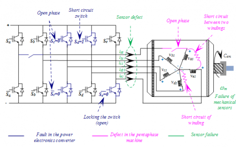
The elements of a training system are interdependent so that a failure in an element can cause the total shutdown of the system and this type of situation has a significant cost in some applications. Several defects can appear on the electric trainings (as shown in Figure 1), they are distributed in the papers [8-11]:
The absence of a feeding phase is less noticeable when their number increases. In this sense shows that according to the acceptable tolerance on the torque ripple, the loss of one of the phases can be admitted without any modification of the command. The measurements made show that indeed the torque ripple is reduced as the number of phase’s increases. In this case no treatment method is used. One of the advantages of power segmentation at the power converter, besides energy quality, is the fault tolerance. In fact, when a power electronics switch is lost due to a malfunction of the control or wear of the control, the system can operate with reduced capacity, which is called degraded mode [11-13]. During this paper, some defects of a polyphase drive system will be studied. These defects are located at the stator of the five-phase induction motor.
To solve these defects, this paper establishes a new modeling of the five phase induction machine in the natural frame (real frame) without adding new circuit or estimated resistance to simulate a fault, with the aim to examine the effect stator oprn phase fault on the performance of five phase induction machine. The open phase fault was created by introduce a high resistance in series with the phase in default, which cancels the current which crosses it. It is indented to provide information about the impact open phase fault on the torque ripples, Joule losses in the stator and rotor, and mechanical speed. The remainder of this paper is organized as follows: Section 2 analysis model of five phase induction machine in degraded mode, and describes the model of the machine, Section 3 presents a computer simulation to endorse the theoretical achievement given in Section 4 Finally some conclusions are made in Section 5.
This section will be dedicated to modeling the five-phase induction motor when opening one or more phases. The impact of such a defect on the temporal evolution of the different quantities of the machine will be implemented. The simulation of this kind of failure is feasible in two different methods with a single objective, which consists of canceling the current flowing through the faulty phase.
2.1 Electrical circuit reconstruction
From this type of approach, the faulty phase is directly removed from the stator electrical circuit. This forces the reformulation of the matrices of the stator.
Figure 1. Different defects that can happen in drive system
2.2 Modeling in the natural frame
This approach consists of modeling the machine in the natural base in a healthy diet. Then introduce a high resistance in series with the phase in default, which cancels the current, which crosses it. With this approach several faults can be simulated.
2.3 Model of the five-phase induction machine in degraded regime in the natural base
The dynamic behavior of the five-phase induction motor is described by the equations mentioned here after where; the voltage equations of five phase induction motor are expressed as follow:
$\left\{\begin{array}{l}{\left[\mathrm{V}_{s}\right]=\left[r_{s}\right]\left[i_{s}\right]+\left[L_{s}\right] \frac{d}{d t}\left[i_{s}\right]+\frac{d\left[i_{r}\right]}{d t}\left[m_{s r}\right]+\frac{\partial\left[m_{s r}\right]}{\partial \theta} \frac{d \theta}{d t}\left[i_{r}\right]} \\ {[0]=\left[r_{r}\right]\left[i_{r}\right]+\left[L_{r}\right] \frac{d}{d t}\left[i_{r}\right]+\frac{d\left[i_{s}\right]}{d t}\left[m_{r s}\right]+\frac{\partial\left[m_{r s}\right]}{\partial \theta} \frac{d \theta}{d t}\left[i_{s}\right]}\end{array}\right.$ (1)
After a few arrangements leading to:
$\left\{\begin{array}{c}\frac{d}{d t}\left[i_{s}\right]=\left[L_{s}\right]^{-1}\left(\left[\mathrm{V}_{s}\right]-\left[r_{s}\right]\left[i_{s}\right]-\frac{d\left[i_{r}\right]}{d t}\left[m_{s r}\right]-\frac{\partial\left[m_{s r}\right]}{\partial \theta} \frac{d \theta}{d t}\left[i_{r}\right]\right) \\ \frac{d}{d t}\left[i_{r}\right]=\left[L_{r}\right]^{-1}\left(-\left[r_{r}\right]\left[i_{r}\right]-\frac{d\left[i_{s}\right]}{d t}\left[m_{r s}\right]-\frac{\partial\left[m_{r s}\right]}{\partial \theta} \frac{d \theta}{d t}\left[i_{s}\right]\right)\end{array}\right.$ (2)
The Eq. (2) can be written in the following form:
$\left\{\begin{array}{r}\left(\frac{d}{d t}\left[\begin{array}{c}i_{s a} \\ i_{s b} \\ i_{s c} \\ i_{s d} \\ i_{s e}\end{array}\right]=\left[L_{s}\right]_{5 x 5}^{-1}\left(\left[\begin{array}{c}v_{a} \\ v_{b} \\ v_{c} \\ v_{d} \\ v_{e}\end{array}\right]-\left[r_{s}\right]_{5 x 5}\left[\begin{array}{c}i_{s a} \\ i_{s b} \\ i_{s c} \\ i_{s d} \\ i_{s e}\end{array}\right]-\left(\frac{d}{d t}\left[\begin{array}{c}i_{r a} \\ i_{r b} \\ i_{r c} \\ i_{r d} \\ i_{r e}\end{array}\right]\right)\left[m_{r s}\right]_{5 x 5}-\frac{\partial\left[m_{s r}\right]_{5 \times 5}}{\partial \theta} \frac{d \theta}{d t}\left[\begin{array}{c}i_{r a} \\ i_{r b} \\ i_{r c} \\ i_{r d} \\ i_{r e}\end{array}\right]\right)\right.&\\ \frac{d}{d t}\left[\begin{array}{c}i_{r a} \\ i_{r b} \\ i_{r c} \\ i_{r d} \\ i_{r e}\end{array}\right]=\left[L_{r}\right]_{5 x 5}^{-1}\left(-\left[r_{r}\right]\left[\begin{array}{c}i_{r a} \\ i_{r b} \\ i_{r c} \\ i_{r d} \\ i_{r e}\end{array}\right]-\left(\frac{d}{d t}\left[\begin{array}{c}i_{s a} \\ i_{s b} \\ i_{s c} \\ i_{s d} \\ i_{s e}\end{array}\right]\right)\left[m_{s r}\right]_{5 x 5}-\frac{\partial\left[m_{r s}\right]_{5 x 5}}{\partial \theta} \frac{d \theta}{d t}\left[\begin{array}{c}i_{s a} \\ i_{s b} \\ i_{s c} \\ i_{s d} \\ i_{s e}\end{array}\right]\right) \end{array}\right.$ (3)
While knowing that the mutual matrix stator / rotor and rotor / stator are given as follows:
$\left[m_{s r}\right]_{5 x 5}=L_{m}\left[\begin{array}{cccc}\cos (\theta) & \cos \left(\theta-\frac{2 \pi}{5}\right) & \cos \left(\theta-\frac{4 \pi}{5}\right) & \cos \left(\theta-\frac{6 \pi}{5}\right) & \cos \left(\theta-\frac{8 \pi}{5}\right) \\ \cos \left(\theta-\frac{8 \pi}{5}\right) & \cos (\theta) & \cos \left(\theta-\frac{2 \pi}{5}\right) & \cos \left(\theta-\frac{4 \pi}{5}\right) & \cos \left(\theta-\frac{6 \pi}{5}\right) \\ \cos \left(\theta-\frac{6 \pi}{5}\right) & \cos \left(\theta-\frac{8 \pi}{5}\right) & \cos (\theta) & \cos \left(\theta-\frac{2 \pi}{5}\right) & \cos \left(\theta-\frac{4 \pi}{5}\right) \\ \cos \left(\theta-\frac{4 \pi}{5}\right) & \cos \left(\theta-\frac{6 \pi}{5}\right) & \cos \left(\theta-\frac{8 \pi}{5}\right) & \cos (\theta) & \cos \left(\theta-\frac{2 \pi}{5}\right) \\ \cos \left(\theta-\frac{2 \pi}{5}\right) & \cos \left(\theta-\frac{4 \pi}{5}\right) & \cos \left(\theta-\frac{6 \pi}{5}\right) & \cos \left(\theta-\frac{8 \pi}{5}\right) & \cos (\theta)\end{array}\right]$
With:
$\left[m_{r s}\right]_{5 x 5}=\left[m_{s r}\right]_{5 x 5}^{t}$ (4)
In addition:
$\frac{\partial\left[m_{s r}\right]}{\partial \theta}=-L_{m}\left[\begin{array}{cccc}\sin (\theta) & \sin \left(\theta-\frac{2 \pi}{5}\right) & \sin \left(\theta-\frac{4 \pi}{5}\right) & \sin \left(\theta-\frac{6 \pi}{5}\right) & \sin \left(\theta-\frac{8 \pi}{5}\right) \\ \sin \left(\theta-\frac{8 \pi}{5}\right) & \sin (\theta) & \sin \left(\theta-\frac{2 \pi}{5}\right) & \sin \left(\theta-\frac{4 \pi}{5}\right) & \sin \left(\theta-\frac{6 \pi}{5}\right) \\ \sin \left(\theta-\frac{4 \pi}{5}\right) & \sin \left(\theta-\frac{6 \pi}{5}\right) & \sin \left(\theta-\frac{8 \pi}{5}\right) & \sin (\theta) & \sin \left(\theta-\frac{2 \pi}{5}\right) \\ \sin \left(\theta-\frac{2 \pi}{5}\right) & \sin \left(\theta-\frac{4 \pi}{5}\right) & \sin \left(\theta-\frac{6 \pi}{5}\right) & \sin \left(\theta-\frac{8 \pi}{5}\right) & \sin (\theta)\end{array}\right]$
With:
$\frac{d \theta}{d t}=P \Omega=\omega$ (5)
The electromagnetic torque is expressed as follow:
$C_{e m}=\frac{P}{2}\left(\left[i_{s}\right]^{t} \frac{\partial\left[m_{s r}\right]}{\partial \theta}\left[i_{r}\right]+\left[i_{r}\right]^{t} \frac{\partial\left[m_{r s}\right]}{\partial \theta}\left[i_{s}\right]\right)$ (6)
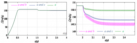
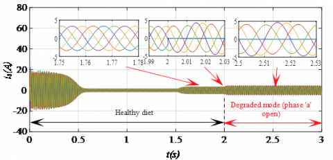
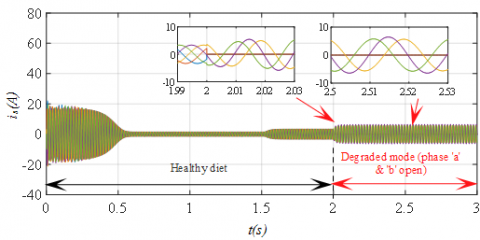
The model has been implemented under MATLAB / Simulink. The machine is started in normal mode, a load of 15 N.m is applied at t=1.5s once the regime is established, the opening of one or two phases is caused at t=2s. In this way several scenarios are studied:
The mechanical performance of the machine (electromagnetic torque, mechanical speed and efficiency) under the various faults are given in Figure 2, Figure 3 and Figure 4 respectively. While Figures 5-7 shows the shape of the stator currents.
Figure 2. Electromagnetic torque of the five phase induction machine under different phase opening faults
Figure 3. Mechanical speed of the five-phase induction machine under different phase opening faults
Figure 4. Efficiency of the five-phase induction machine under different phase opening faults
Figure 5. Stator current of the five-phase induction machine with the phase “a” open
Figure 6. Stator current of the five-phase induction machine with the phase “a and c” open
Figure 7. Stator current of the five-phase induction machine with the phase “a and b” open
Given the large number of tests and data obtained, it is difficult to interpret all defects that can arise in a traction system. To overcome this difficulty a multi-variable (multidimensional) analysis is required.
For this, we have gathered all the data obtained in a single table with as witness current. This table will be processed by a Principal Components Analysis method that can be done with several statistical packages such as (Statistical, R, and SAS), for our analysis, the XLSTAT software is used.
When studying a large number of quantitative variables simultaneously. The difficulty comes from the fact that the individuals studied are no longer represented in a plane, two-dimensional spaces, but in a larger dimension space. The goal of Principal Component Analysis (PCA) is to return to a two-dimensional space while preserving as much information as possible. It is therefore necessary to obtain the most relevant summary of the initial data.
It is the variance-covariance matrix (or that of the correlations) that will make it possible to produce this relevant summary, because we essentially analyze the dispersion of the considered data. From this matrix, we will extract, by an appropriate mathematical process, the factors we are looking for, in small numbers. They will make it possible to realize the desired graphs in this small space, by deforming as little as possible the global configuration of the individuals as is defined by the set of initial variables. It is the interpretation of these graphs that will make it possible to understand the structure of the analyzed data.
Figure 8. Correlation circle
Before dealing with all the defects in the drive system, we here propose to treat the first fault family. We start with phase-opening faults with a balanced sinusoidal supply. We applied the PCA in Table 1 to do this we must first identify the statistical individuals, for our case the default types are considered as statistical individuals that are noted (S, D1, D2 and D3).
From the Table 2 a strong correlation of electromagnetic torque with speed and efficiency is noticed, but the fundamental of current inverse correlation with speed and efficiency. According to the Table 3, all the variables are in perfect agreement with the first fictitious component of the PCA.
The circle of correlations illustrated in the Figure 8 gives an immediate synthetic view of the interactions between the variables in a very explicit graphical way. The angle between Cmoy em, Wmoy and hmoy is low which means a strong correlation. On the other hand, the angle between the hmoy and ifon d is around 180°, which means a strong inverse correlation between these two.
The diagram (see Figure 9) groups the first factorial plane with the circle of correlations that allows us to better compare the interactions that exist between the deferential variables with the deferential phase opening defects. The healthy regime superimposes on the range of Wmoy and as the Euclidean distance separating the defect D1 of S is the weakest, and as the correlation between then Wmoy and ifon d very weak then D1 is not dangerous a short term. However, the defects D2 and D3 are further Wmoy and as they are closer to the ifon d then these two defects are more dangerous than D1, is the latter that should be monitored the most. What is sense, the loss of a phase is less harmful than the loss of two phases.
Figure 9. Representation of individual
Table 1. Failure to open phase with a direct supply
|
Code |
Default type |
$\Gamma_{e m}^{\operatorname{moy}}(N . m)$ |
$i_{d}^{f o n}(A)$ |
$\Omega^{m o y}(r d / s)$ |
$\boldsymbol{\eta}^{m o y}$ |
THD(%) |
|
S |
Healthy |
13.35 |
3.375 |
150.8 |
0.9 |
0.01 |
|
D1 |
Opening of phase “a” |
13.31 |
4.623 |
150.46 |
0.882 |
0.03 |
|
D2 |
Opening of phases “a” and “b" |
13.226 |
6.34 |
149.878 |
0.8508 |
0.04 |
|
D3 |
Opening of phases “a” and “c" |
13.17 |
6.522 |
149.629 |
0.8505 |
0.06 |
|
Variables |
$\Gamma_{e m}^{\operatorname{moy}}(N . m)$ |
$i_{d}^{f o n}(A)$ |
$\Omega^{m o y}(r d / s)$ |
$\boldsymbol{\eta}^{m o y}$ |
THD (%) |
|
$\boldsymbol{\eta}^{m o y}$ |
1 |
-0.963 |
0.994 |
0.957 |
-0.970 |
|
$i_{d}^{f o n}(A)$ |
-0.963 |
1 |
-0.987 |
-0.998 |
0.934 |
|
$\Omega^{m o y}(r d / s)$ |
0.994 |
-0.987 |
1 |
0.982 |
-0.964 |
|
$\boldsymbol{\eta}^{m o y}$ |
0.957 |
-0.998 |
0.982 |
1 |
-0.913 |
|
THD(%) |
-0.970 |
0.934 |
-0.964 |
-0.913 |
1 |
|
F1 |
F2 |
|
|
$\boldsymbol{\eta}^{m o y}$ |
0.981 |
0.007 |
|
$i_{d}^{f o n}(A)$ |
0.980 |
0.017 |
|
$\Omega^{m o y}(r d / s)$ |
0.998 |
0.000 |
|
$\boldsymbol{\eta}^{m o y}$ |
0.967 |
0.032 |
|
THD(%) |
0.940 |
0.053 |
In this paper a new analysis model of stator open phase faults in a five-phase induction motor was presented. The method used in this work based on the use of model in the natural frame was clearly mentored, and the most advantage of this model is that it can be used easily to study the defects resulting from connections or disconnections winding, as it was demonstrated in this paper, and also the magnetic non-linearity and the effect of space harmonics are taken into account which makes the analysis more interesting. The results provided by the method of classification (PCA) are very encouraging despite this type of statistical tool is little used until now in the field of electrical machinery, or in this work demonstrate the interest of this method since it makes the variables homogeneously balanced between them and provided a set of correlations of the variables which makes the collection of information and effects very easy.
This paper allowed us to synthesize the effect of stator open phase faults while focusing on their genesis and effect, and always has as results in different cases, an increase in torque ripples and decrease in mechanical speed and efficiency, where there is a strong correlation between electromagnetic torque, mechanical speed and efficiency, or there is a strong inverse correlation between efficiency and fundamental of current.
|
f |
Viscous friction |
|
j |
Inertia |
| $i_{s}$ | Stator currents |
| $i_{r}$ | Rotor currents |
| $L_{m}$ | Magnetizing inductance |
| $L_{s}$ | Per phase stator leakage inductance |
| $L_{r}$ | Per phase rotor leakage inductance |
| $P$ | Number of pole pairs |
| $R_{r}$ | Rotor resistances |
| $R_{s}$ | Stator resistances |
| $v_{r}$ | Rotor voltage |
| $v_{s}$ | Stator voltage |
|
Greek symbols |
|
|
$\psi_{r}$ |
Rotor flux |
|
$\psi_{s}$ |
Stator flux |
|
$\theta_{r}$ |
Electrical angle |
|
$\Gamma_{e m}$ |
Electromagnetic torque |
|
$\omega_{r}$ |
Rotor electrical speed |
|
$\Omega_{r}$ |
Rotor mechanical speed |
[1] Duran, M.J., Barrero, F. (2016). Recent advances in the design, modelling and control of multiphase machines. IEEE Trans on Industrial Electronics, 63(1): 449-458. https://doi.org/10.1109/TIE.2015.2447733
[2] Iffouzar, K., Benkhoris, M.F., Auozellag, H., Ghedamsi, K., Auozellag D. (2017). Direct rotor field oriented control of polyphase induction machine based on fuzzy logic controller. Rev. Roum. Sci. Techn. -Electrotech. Et Energ., 62(1): 42-47.
[3] Iffouzar, K., Taraft, S., Auozellag, H., Ghedamsi, K., Auozellag, D. (2015). Behavior of six phase Induction motor fed by multilevel inverter. International conference of Electrical Engineering, ICEE15, Algeria, pp 1-7. https://doi.org/10.1109/INTEE.2015.7416779
[4] Appiah, E.K., M’boungui, G., Jimoh, A.A., Munda, J.L., Ogunjuyigbe, A.S. (2013). Symmetrical analysis of a six phase induction machine under fault conditions. International Journal of Electrical and Computer Engineering, 7(3): 324-331. https://doi.org/10.5281/zenodo.1055184
[5] Sobanski, P., Orlowska-Kowalska, T. (2015). Faults diagnosis and control in a low-cost fault-tolerant induction motor drive system. Mathematics and Computers in Simulation, 131: 217-233. https://doi.org/10.1016/j.matcom.2015.10.012
[6] Hu, Y., Zhang, L., Huang, W., Bu, F. (2010). A fault-tolerant induction generator system based on instantaneous torque control (ITC). IEEE Transactions on Energy Conversion, 25(2): 412-421. https://doi.org/10.1109/TEC.2009.2038898
[7] Munim, M., Duran, M., Che, H.S., Bermudez, M., Gonzalez-Prieto, I., Abd Rahim, N. (2017). A unified analysis of the fault tolerance capability in six-phase induction motor drive. IEEE Trans. Power Electron., 32(10): 7824-7836. https://doi.org/10.1109/TPEL.2016.2632118
[8] Yassa, N., Rachek, M. (2018). Modeling and detecting the stator winding inter turn fault of permanent magnet synchronous motors using stator current signature analysis. Mathematics and Computers in Simulation, 167: 325-339. https://doi.org/10.1016/j.matcom.2018.04.012
[9] Abdel-Khalik, A.S., Morsy, A., Ahmed, S., Massoud, S. (2014). Effect of stator windingconnection on performance of five-phase induction machines. IEEE Trans. Ind. Elect., 61(1): 3-19. https://doi.org/10.1109/TIE.2013.2242417
[10] Wu, H., Depernet, D., Lanfranchi, V. (2018). Analysis of torque ripple reduction in a segmented-rotor synchronous reluctance machine by optimal currents. Mathematics and Computers in Simulation, 158: 130-147. https://doi.org/10.1016/j.matcom.2018.07.001
[11] Riedemann, J., Andrade, I., Peña,R., Blasco-Gimenez, R., Clare, J., Melín, P., Riverae, M. (2016). Modulation strategies for an open-end winding induction machine fed by a two-output indirect matrix converter. Mathematics and Computers in Simulation, 130: 95-111. https://doi.org/10.1016/j.matcom.2016.05.007
[12] Rangari, S.C., Suryawanshi, H.M., Renge, M. (2018). New fault control strategy of five phase induction motor with four-phase and three-phase modes operation. Journal of Electronics, 7(9): 159. https://doi.org/10.3390/electronics7090159
[13] Marques, M., Martins, J., Pires, V., Jourge, R., Meudes, L. (2013). Fault Detection and Diagnosis in Induction Machines: A Case Study. In: Camarinha-Matos L.M., Tomic S., Graça P. (eds) Technological Innovation for the Internet of Things. DoCEIS 2013. IFIP Advances in Information and Communication Technology, vol 394. Springer, Berlin, Heidelberg. https://doi.org/10.1007/978-3-642-37291-9_30