OPEN ACCESS
The main objective of this paper is to apply fuzzy control to push-pull fly-back three-phase DC-DC convertor. For this purpose, firstly, the push-pull fly-back three-phase DC-DC convertor is investigated. This structure can operate in the entire range of D variations. The high impedance generated by coupler loopholes prevents trans-saturation. Finally, the simulation results show the accuracy of the converter's performance in two different values for the reference voltage.
DC-DC converter, fuzzy control, push-pull, flyback, three phase converter
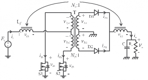
The use of the DC-DC isolation converters structure has now been highly sought after by the experts, since these converters have both an inlet and outlet isolation and a range of output voltage variations that are larger than classical structures [1-2], and there are several outputs available for them. One of the structures used in low-voltage isolated DC-DC converters is the push-pull converter, which has a simple structure, and with its high efficiency in the two-quarter curve of the B-H core [3]. The important form of such structures is that they carry energy for D less than 50 %, and D cannot vary from 0 to 100 % [4]. To resolve this problem, push-pull fly-back structure of the source is used, which is as follows:
Figure 1. Push-pull fly-back converter
In this converter, the coupled inductors make the transient winding transmit energy throughout the range of energy changes. The above structure, which is based on trans-single-phase, can be generalized in the form of three phases [5], which we will introduce in this chapter the three-phase type. This structure can operate in the entire range of D variations [6]. The high impedance created by couplings prevents trans-saturation. Transistors are driven by a reference voltage and due to the use of the three-phase structure [7], the frequency of the filters is three times the switching frequency and the filter values will decrease [8].
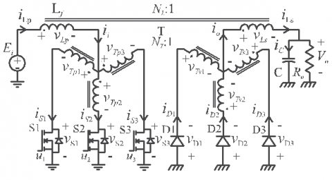
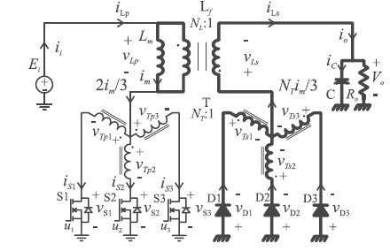
The figure below shows circuit of three phases push-pull flyback converter:
Figure 2. Push-pull flyback three phase converter
The remainder of this paper is organized as follows: Section 2 introduces the push pull flyback converter. Section 3 describes the calculation of voltage gain of converter. Section 4 introduces the fuzzy control. Section 5 describes the simulation results. Section 6 describes the conclusion
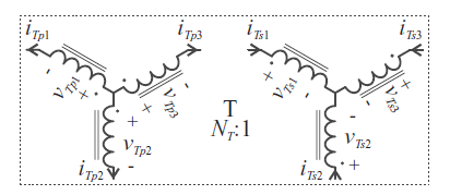
This circuit has three switches S1, S2, S3, three diodes D1, D2, D3, coupled inductor Lf and output capacitance C. Trans three-phase star-star used in this converter has the following orbital structure:
Figure 3. Circuit structure of three-phase transformer
Trans structure is as follows:
Figure 4. Trans-phase three-phase physical structure
Depending on the duty cycle of the switches (D), three areas of work can be defined for this converter, which are defined in the following table:
Table 1. Converters work areas
|
Region |
Duty cycle range |
Overlapping conduction |
|
R1 |
0≤D<1/3 |
None |
|
R2 |
1/3≤D≤2/3 |
Two transistors |
|
R3 |
2/3<D≤1 |
Three transistors |
2.1 Region R1
The main waveforms for this area are as follows:
Figure 5. Waveforms related to area R1
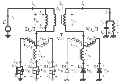
This area has two functional states. At the moment t0, the switch S1 starts to direct, and the diodes D2, D3 are connected, and the converter circuit is as follows:
Figure 6. The first state circuit R1
In the second position, the instant t1, the switch S1 is cut off and all three diodes will be diverted and the circuit will be as follows:
Figure 7. The second state circuit R1
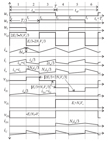
2.2 Region R2
The main waveforms for this area are as follows:
Figure 8. The waveforms of the region R2
This area also has two operating conditions. In the first state, the moment t0, the switches S1, S3 will be diverted, and only the D2 diodes will be connected, and the converter circuit will be as follows:
Figure 9. The first state circuit R2
In the second state, the instant t1, only the S1 switch will be located and will be the same as the first state of the R1 region.
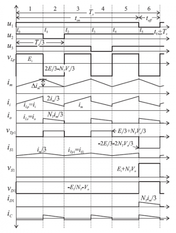
2.3 Region R3
The main waveforms for this area are as follows:
Figure 10. Waveforms related to area R3
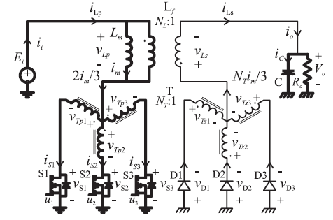
In the first state of this region, the moment t0, all three switches are diverted and all three diodes are disconnected and the converter circuit is as follows.
In the second situation, namely moment t1, the switches S1, S3 will be directed and will be similar to the first state of the region R2.
Figure 11. The first state circuit R3
For this purpose, as the following can be used volt per second balance for VLP:
$V_{L P}=\frac{1}{T_{s}} \int_{t_{0}}^{t_{0}+T_{s}} V_{L P} d t=\frac{3}{T_{s}} \int_{t_{0}}^{t_{2}} V_{L P} d t=0$ (1)
The above equation in the regions R1, R2 and R3 will be as follows:
$\left(E_{i}-2 N_{T} V_{0}\right) t_{o n}-N_{T} V_{0}\left(\frac{T_{s}}{3}-t_{o n}\right)=0$ (2)
$\left(2 E_{i}-N_{T} V_{0}\right)\left(t_{o n}-\frac{T_{s}}{3}\right)+\left(E_{i}-2 N_{T} V_{0}\right)\left(\frac{2 T_{s}}{3}-t_{o n}\right)=0$ (3)
$\left(E_{i}\right)\left(t_{o n}-\frac{2 T_{s}}{3}\right)+\left(2 E_{i}-N_{T} V_{0}\right)\left(T_{s}-t_{o n}\right)=0$ (4)
The result of solving each of the above equations will result in the same result:
$\frac{V_{O}}{E_{i}}=\frac{D}{N_{T}(1-D)}$ (5)
which indicates that the gain of this converter is similar to the conventional fB converter.
As mentioned, the main purpose of this paper, the application of fuzzy control methods to control the push-pull-flyback three-phase DC-DC converter. In general, the use of the fuzzy method for various systems has found application. This method has been used in electrical systems and in various branches of electrical engineering, including the following:
- Types of electric drives
- Flexible AC Transmission Systems (FACTS)
- Controlling Electronic Power Controllers
- Electromechanical systems
- Distributed production systems
An important advantage of the fuzzy method is that it can provide proper control for the system without having to know the exact mathematical model of the system [9].
4.1 Fuzzy control in DC-DC converters
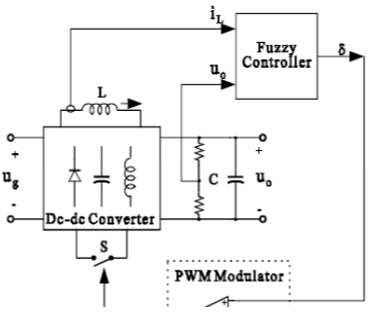
The block diagram of the overall fuzzy control in DC-DC converters is shown in Figure 12. As shown in this figure, the error and error derivative are applied as input to the fuzzy controller and the fuzzy controller output determines the duty cycle of the switch. Now, comparing the output of the fuzzy controller with a sawdust waveform, the command signal to the switch is generated, as shown in Figure 13.
Figure 12. Block diagram of the fuzzy control of the converters
Figure 13. How to generate the command signal to the switch
4.2 Fuzzy control simulation
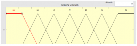
For this purpose, the fuzzy control toolbox is used in MATLAB software. In this paper, two inputs for the fuzzy controller are considered, which are voltage error (e) and voltage derivative (ce). The voltage error is obtained from the differential voltage output and reference voltage. The membership functions used for these inputs are as follows:
Figure 14. Membership function of (e)
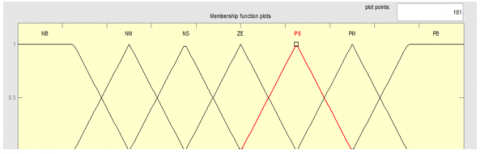
Figure 15. Membership function (ce)
The controller output membership function is as follows:
Figure 16. Membership function of output
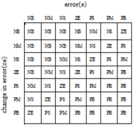
The fuzzy rules used are as follows:
Figure 17. Fuzzy rules
The following principles have been used to write the fuzzy rules:
- When the output voltage is far from the reference value, the duty cycle of the switch must be large.
- When the output voltage approaches the reference value, the duty cycle must be small.
- When the output voltage reaches the reference value and remains stable, the duty cycle must remain unchanged.
- When the output voltage reaches the reference value but is still changing and not stable, the duty cycle should be small.
When the output voltage is greater than the reference value, the duty cycle changes must be negative and vice versa.
Here, the converter is under the following simulation parameters:
Vin = 100 (V)
F= 42 (KHz)
NT= 1/2
NL=1/2
Lm=12 (uH)
Cf=2000 (uF)
R=10 (ohm)
5.1 Simulation results for a reference voltage of 100 volts
In this section, simulation results are presented for two reference voltages of 100 and 200 volts. A. simulation results per 100 volts reference voltage. In this case, the reference voltage of 100 volts is applied to the control system. In this situation, the output voltage waveform of the converter will be as follows:
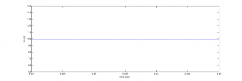
Figure 18. Output voltage
As shown in this figure, the output voltage has been able to track the reference value with a slight error and reach 100 volts. In this situation, the output of the fuzzy controller, which is the same duty cycle of the switch, will be as follows:
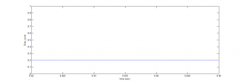
Figure 19. The duty cycle
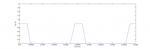
As shown in the figure above, the duty cycle of the switches is about 20 %. In this situation, the waveform of the command signal to the switches will be as follows:
Figure 20. The command signal to switch 1
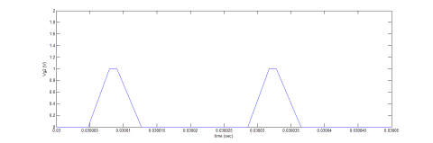
Figure 21. The command signal to switch 2
As you can see in Figure 22, switches are switched at 42 kHz and their duty cycle is about 20 %.
5.2 Simulation results for a reference voltage of 200 volts
In this case, the reference voltage of 200 volts is applied to the control system. In this situation, the output voltage waveform of the converter will be as Figure (23).
Figure 22. The command signal to switch 3
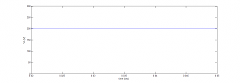
Figure 23. Output voltage
As shown in this figure, the output voltage has been able to track the reference value with a slight error and reaches a value of 200 volts. In this situation, the output of the fuzzy controller, which is the same duty cycle of the switch, will be as follows:
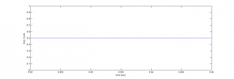
Figure 24. Duty cycle
As shown in the figure above, the duty cycle of the switches is about 50 %. In this situation, the waveform of the command signal to the switches will be as follows:
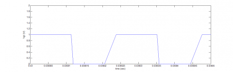
Figure 25. The command signal to switch 1
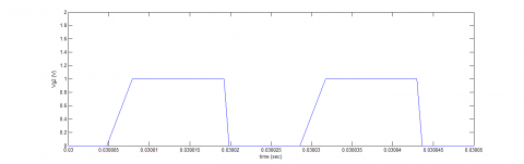
Figure 26. Command signal of switch 2
Figure 27. The command signal to switch 2
As you can see, switches are switched at 42 kHz and their duty cycle is about 50 %.
The main objective of this paper is to use fuzzy control of push-pull fly-back three-phase DC-DC convertor. To this end, we first introduced the fuzzy control, and its basic concepts and applications were discussed in detail. The important advantage of using the fuzzy control method is that in this method it is not necessary to know the exact mathematical model of the converter. In the following, the controller for controlling push-pull fly-back three-phase DC-DC convertor was investigated. This structure can operate in the entire range of D variations. The high impedance created by couplings prevents trans-saturation. Finally, the simulation results show the accuracy of the converter's performance in two different values for the reference voltage. For future studies, the optimization of fuzzy controller is recommended.
[1] Ershadi, M.H., Poudeh, M.B., Eshtehardiha, S. (2008). Fuzzy logic controller based genetic algorithm on the step-down converter. International Conference on Smart Manufacturing Application. http://dx.doi.org/10.1109/ICSMA.2008.4505667
[2] Choi, Y., Jeon, H., Kim, Y.B. (2013). A switched-capacitor DC-DC converter using delta-sigma digital pulse frequency modulation control method. Circuits and Systems (MWSCAS), 2013 IEEE 56th International Midwest Symposium on, pp. 356-359. http://dx.doi.org/10.1109/MWSCAS.2013.6674659
[3] Chung, H., Ioinovici, A. (1996). Switched-capacitor-based DC-to-DC converter with improved input current waveform. In Proceedings IEEE Int. Symp. Circuits and Systems, Atlanta, USA, pp. 541-544. http://dx.doi.org/10.1109/ISCAS.1996.540004
[4] Makowski, M.S., Maksimovic, D. (1995). Performance limits of switched-capacitor DC-DC converter. IEEE PESC’95 Conf., pp. 1215-1221. http://dx.doi.org/10.1109/PESC.1995.474969
[5] Makowski, M.S. (1997). Realization conditions and bound on synthesis of switched-capacitor DC-DC voltage multiplier circuits. IEEE Trans. Circuits Syst.-I: Fundamental Theory and Appl., 44(8): 684-691. http://dx.doi.org/10.1109/81.611263
[6] Joy, J., Ushakumari, S. (2018). Performance comparison of a bridge-less canonical switching cell and H-bridge inverter with SVPWM fed PMBLDC motor drive under fuzzy logic controller. Modelling, Measurement and Control A, 91(4): 193-201. http://dx.doi.org/10.18280/mmc_a.910405
[7] Makowski, M.S. (2008). On performance limits of switched-capacitor multi-phase charge pump circuits. Remarks on paper of Starzyk et al. Int. Conf. on Signals and Electronic Systems, pp. 309-312. http://dx.doi.org/10.1109/ICSES.2008.4673422
[8] Van Breussegem, T.M., Wens, M., Geukens, E., Geys, D, Steyaert, M.S.J. (2008). Area-driven optimisation of switched-capacitor DC/DC converters. Electronics Letters, 44(25): 1488-1490. http://dx.doi.org/10.1049/el:20081687
[9] Manukonda, D., Gorantla, S.R. (2018). A fuzzy logic controller based vortex wind turbine for commercial applications. Modelling, Measurement and Control A, 91(2): 54-58. https://doi.org/10.18280/mmc_a.910204