
Rajesh Murali | Mahesh Vatal Mahadevappa | Karthik Machahalli Shivarudraiah* | Dayanandamurthy Thandavamurthy
© 2026 The authors. This article is published by IIETA and is licensed under the CC BY 4.0 license (http://creativecommons.org/licenses/by/4.0/).
OPEN ACCESS
This comparative study investigated the influence of stacking sequence on the open-hole tensile behaviour of plain-woven carbon fibre-reinforced polymer (CFRP)/glass fibre-reinforced polymer (GFRP) laminates. Four architectures were examined: GFRP, a carbon-core hybrid, a carbon-faced hybrid, and CFRP. Five unnotched and five open-hole coupons were tested for each architecture (n = 5 per condition; 40 coupons in total), and one representative microphone trace was retained for each architecture and loading condition. Specimen geometries were adapted from ASTM International tensile and open-hole standards; the hole diameter-to-width ratio (D/W) was 0.24. Gross-section ultimate tensile strength (UTS) was calculated from maximum force and measured width and thickness. Mean UTS values (mean ± standard deviation (SD)) were 1062.6 ± 29.1 MPa unnotched and 683.6 ± 16.8 MPa open-hole for GFRP; 890.2 ± 24.4 and 659.0 ± 16.2 MPa for the carbon-core hybrid; 783.5 ± 21.4 and 631.1 ± 15.5 MPa for the carbon-faced hybrid; and 1178.1 ± 32.2 and 879.3 ± 21.7 MPa for CFRP. Open-hole strength retention (SR) was 64.3 ± 0.2%, 74.0 ± 0.2%, 80.6 ± 0.2%, and 74.6 ± 0.2%, respectively. Microphone recordings were compared as raw time-domain voltage traces using a common acquisition time base; no filtering, denoising, or amplitude normalization was applied to the time-domain plots. The recordings were interpreted as comparative audible/vibration-response chronologies rather than mechanism-specific acoustic-emission classifications. Within the tested configurations, the carbon-faced hybrid gave the highest normalized retention, whereas CFRP retained the highest absolute tensile strength.
CFRP/GFRP laminates, hybrid composites, microphone-recorded response, notch sensitivity, open-hole tensile behaviour, stacking sequence, strength retention
Fibre-reinforced polymer (FRP) composites are widely used in structural applications because of their high specific strength, corrosion resistance, and design flexibility. Carbon fibre-reinforced polymer (CFRP) is typically stiffer and stronger, whereas glass fibre-reinforced polymer (GFRP) can exhibit more progressive damage and energy absorption. Hybrid CFRP/GFRP laminates can therefore be used to balance absolute tensile capacity and notch-sensitive behaviour in components containing holes, cut-outs, and access openings [1-3].
The open-hole tensile test evaluates notch sensitivity and residual load-carrying capacity. Open-hole behaviour depends on fibre type, ply architecture, laminate thickness, fibre content, and hole geometry [1, 4, 5]. Direct comparisons between carbon-core and carbon-faced hybrid architectures manufactured and tested under a common workflow remain limited.
Microphone monitoring provides a time-synchronized record of audible and vibration-related responses during tensile loading. Here, an external microphone was used instead of a coupled piezoelectric acoustic-emission sensor. The recordings were therefore compared only in terms of response onset, burst chronology, and relative waveform intensity, without assigning the observed features to microscopic damage sources.
In this study, four laminate architectures were fabricated and tested using a common nominal areal density, specimen geometry, conditioning procedure, and tensile protocol: GFRP, CFRP, a carbon-core hybrid with GFRP faces, and a carbon-faced hybrid with a GFRP core. Five unnotched and five open-hole coupons were tested for each architecture. The goals were to measure gross-section unnotched and open-hole strengths, quantify normalized strength retention (SR), compare microphone-recorded response chronology, and relate the measured trends to visible fracture appearance. Because laminate thickness and fibre composition varied among the architectures, the results are interpreted as a comparison of the complete laminate configurations rather than as an isolated stacking-sequence effect.
2.1 Materials and laminate configurations
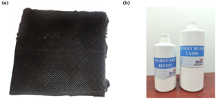
Commercial plain-weave carbon and E-glass fabrics were used as reinforcements. The carbon fabric was a 400 g/m², 12K plain-weave bidirectional fabric supplied by Funique Composites Pvt. Ltd.; the working fibre density was 1.80 g/cm³, with nominal fibre tensile strength of 4000 MPa and modulus of 240 GPa. The E-glass fabric was a 200 g/m² plain-weave fabric from Funique Composites Pvt. Ltd.; the working fibre density was 2.54 g/cm³, with nominal fibre tensile strength of 2400 MPa and modulus of 72 GPa. The matrix was Araldite LY 556 epoxy with HY 951 hardener from Huntsman Advanced Materials/Huntsman International (India) Private Limited as shown in Figure 1, mixed at 100:10 by weight. Working cured-resin values used for data cross-checking were density 1.19 g/cm³, tensile strength 52 MPa, tensile modulus 2.8 GPa, and elongation at break 11%. The target fibre volume fraction (Vf) was 55% for the laminate configurations summarized in Table 1. Vf was estimated from total fibre areal mass, constituent fibre densities, and measured laminate thickness; constituent fibre volumes were summed for the two hybrid architectures. The resulting estimates were 55.2% for Set I, 55.1% for Set II, 55.1% for Set III, and 55.0% for Set IV. These values are mass/thickness estimates rather than direct burn-off measurements.
Figure 1. Reinforcement fabric and LY556-HY951 epoxy system: (a) plain-weave carbon fabric and (b) resin-hardener system
Table 1. Lay-up architectures and measured laminate properties
|
Set |
Laminate Type |
Stacking Sequence |
Total Plies; Areal Density |
Measured Thickness; Gross Area |
|
I |
GFRP |
[G/G/G/G/G/G/G/G] |
8 plies; 1600 g/m² |
1.141 mm; 28.525 mm² |
|
II |
Carbon-core hybrid |
[G/G/C/C/G/G] |
6 plies; 1600 g/m² |
1.3785 mm; 34.463 mm² |
|
III |
Carbon-faced hybrid |
[C/G/G/G/G/C] |
6 plies; 1600 g/m² |
1.3785 mm; 34.463 mm² |
|
IV |
CFRP |
[C/C/C/C] |
4 plies; 1600 g/m² |
1.6162 mm; 40.405 mm² |
Note: Glass fibre-reinforced polymer (GFRP), carbon fibre-reinforced polymer (CFRP).
2.2 Fabrication procedure
Panels were fabricated by controlled hand lay-up on a flat mold treated with a release agent. Resin was applied uniformly, and the plies were consolidated with calibrated weights at an approximate pressure of 0.35 MPa. The resin system was degassed for 5-10 min before use. Panels were cured at room temperature for 24 h and post-cured at 80 ℃ for 2 h. After demoulding, the panels were trimmed and visually inspected; panels showing visible fabrication defects or thickness outside the specified tolerance were excluded. The fabrication and machining details are summarized in Table 2.
Table 2. Fabrication, machining, conditioning, geometry, and test parameters
|
Parameter |
Value |
Parameter |
Value |
|
Resin: hardener |
100:10 by weight |
Degassing |
5-10 min |
|
Consolidation |
Flat plate; calibrated weights |
Pressure |
Approx. 0.2-0.5 MPa |
|
Room cure |
24 h |
Post-cure |
80 ℃ for 2 h |
|
Cutting |
Abrasive water jet |
Hole route |
Pilot drilling + water-jet enlargement |
|
Drill speed |
1,500-2,500 rpm |
Feed practice |
Light peck feed; backing plate |
|
Deburring |
400-600 grit emery |
Inspection |
Stereomicroscope; reject visible damage |
|
Conditioning |
23 ± 2 ℃; 50 ± 5% relative humidity (RH); 48 h |
Reference geometries |
ASTM D3039/D3039M; ASTM D5766/D5766M [6, 7] |
|
Width/overall length |
25/250 mm |
Gauge length |
150 mm reported |
|
Hole diameter |
6 ± 0.05 mm |
D/W |
0.24 |
|
Data acquisition |
Load and displacement; Dewesoft synchronization |
Stress calculation |
Gross section: Fmax/(w × t) |
2.3 Specimen preparation
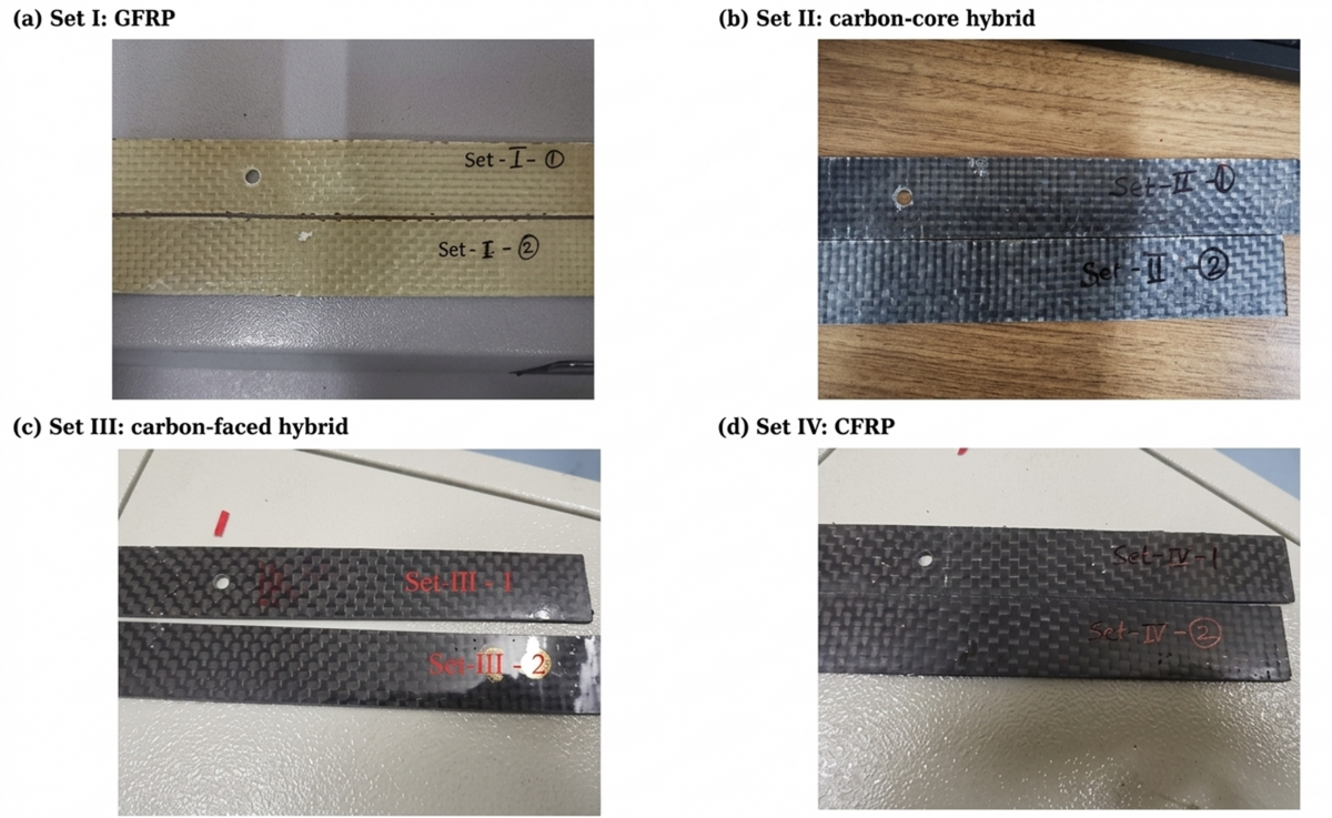
Specimen dimensions were adapted from ASTM International (ASTM) D3039/D3039M for unnotched tension and ASTM D5766/D5766M for open-hole tension [6, 7]. Coupons were cut to the required outer profile by abrasive water-jet machining. For open-hole specimens, a pilot hole established the hole centre and water-jet enlargement produced the final diameter. Edge and hole surfaces were lightly deburred and inspected under a stereomicroscope; specimens showing visible delamination or machining-induced damage were rejected.
Five unnotched and five open-hole coupons were prepared and tested for each laminate architecture (n = 5 per condition; 40 mechanical coupons in total). The corresponding surface condition, central-hole position, and specimen type are documented in Figure 2.
2.4 Mechanical testing procedures
Quasi-static unnotched and open-hole tensile tests were performed on conditioned specimens using a servo-hydraulic universal testing machine with a calibrated load cell. Specimen geometries were adapted from ASTM D3039/D3039M and ASTM D5766/D5766M [6, 7]. Dimensions, hole diameter, D/W ratio, hole-finishing procedure, conditioning, and rejection criteria are summarized in Table 2. Load and displacement were recorded continuously. For each laminate architecture, five specimens were tested under each condition.
2.4.1 Unnotched tensile test
Unnotched tensile tests established the baseline maximum force (Fmax) and gross-section ultimate tensile strength (UTS) for each laminate. Specimens were gripped to avoid end failures and loaded under displacement control until fracture. Peak force and fracture location were recorded for all five replicate specimens.
2.4.2 Open-hole tensile test
Open-hole coupons were tested under the same displacement-controlled protocol, with the central circular hole acting as the stress concentrator. Gross-section UTS was calculated as Fmax/(w × t), using the measured specimen width and thickness and disregarding the hole area. Open-hole SR was calculated for each matched specimen pair by dividing open-hole UTS by the corresponding unnotched UTS. The common gross-section stress convention enables comparison among the four laminate architectures.
2.5 Microphone-based monitoring and data acquisition
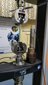
During tensile testing, fracture-noise response was recorded with an external microphone integrated with the test arrangement as illustrated in Figure 3, while the universal testing machine measured load and displacement. Dewesoft was used for synchronized acquisition and export. The supplied time-domain records contained 2048 samples at a sampling frequency of 1000 Hz, giving a record duration of 2.047 s per trace. Amplitude is reported as raw microphone voltage (V); no microphone calibration to sound-pressure level was applied or documented. Mechanical and microphone streams shared a common acquisition time base.
For the revised time-domain plots, the raw microphone traces were used without filtering, denoising, fixed noise-gate thresholding, or amplitude normalization. The traces were plotted directly in volts on a common y-axis range so that relative response intensity could be compared. A 2048-point one-sided fast Fourier transform (FFT), with a Hann window and frequency resolution of 0.488 Hz, was used only as an internal spectral check; the present discussion does not assign frequency bands to specific damage mechanisms. Qualitative response onset was taken as the first sustained visible departure from the quiescent baseline, not as a fixed voltage threshold.
Figure 3. Tensile-test and external microphone-recording arrangement
2.6 Data analysis and comparison
Ultimate tensile strength was calculated as UTS = Fmax/(w × t), where w = 25 mm and t is the measured laminate thickness in Table 1. For open-hole coupons, the gross-section area was used. For each architecture, mean Fmax and mean UTS are reported with the sample standard deviation (SD) from five specimens. SR was calculated specimen-by-specimen as SR = 100 × UTSopen-hole/UTSunnotched and then summarized as mean ± SD. This paired calculation preserves the correspondence between open-hole and unnotched coupons.
Measured results are compared across the four laminate architectures tested under the common fabrication and loading workflow. The mechanical comparisons are specimen-level summaries (n = 5 per condition) and are not treated as population-level statistical allowables. Because thickness and fibre composition varied among the configurations, the observed differences are interpreted as combined architecture effects rather than as evidence that stacking sequence alone controlled the response.
Microphone-response trends were compared with the synchronized mechanical record and post-test macroscopic observations to describe relative response chronology. The acoustic dataset comprised eight representative traces (four architectures × two loading conditions) and was not subjected to specimen-level statistical inference.
3.1 Unnotched tensile behaviour
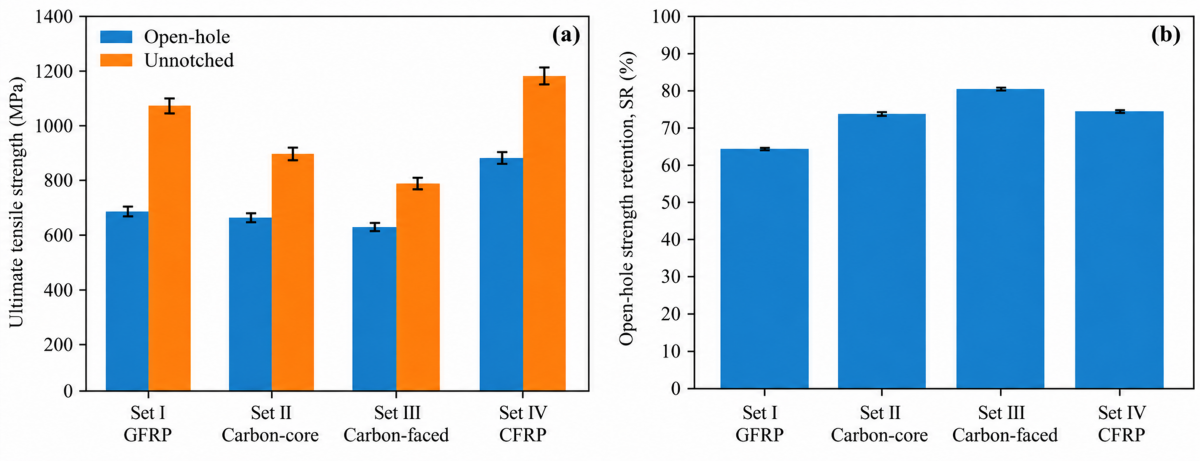
Five replicate unnotched tests were performed for each architecture. The mean unnotched UTS ranking was Set IV CFRP (1178.1 ± 32.2 MPa) > Set I GFRP (1062.6 ± 29.1 MPa) > Set II carbon-core hybrid (890.2 ± 24.4 MPa) > Set III carbon-faced hybrid (783.5 ± 21.4 MPa). Figure 4(a) shows the mean gross-section UTS values with sample standard-deviation bars.
The carbon-core hybrid had the higher absolute unnotched strength of the two hybrid layouts, whereas the carbon-faced hybrid later showed the higher normalized open-hole retention. This distinction separates absolute load capacity from resistance to notch-induced strength reduction.
Table 3 summarizes the mean maximum force and gross-section UTS with SD for all five replicates. The open-hole and unnotched results were obtained using the same measured thickness and gross-section stress convention.
Table 3 and Figure 4(a) show that CFRP provided the highest mean absolute tensile strength under both loading conditions. Among the hybrids, the carbon-core laminate showed higher mean absolute unnotched and open-hole UTS, whereas the carbon-faced laminate showed the highest mean normalized SR. The variability bars show that the replicate scatter was small relative to the differences among the laminate configurations.
Table 3. Mean maximum force, gross-section tensile strength, and open-hole strength retention (SR) for n = 5 specimens per condition
|
Set |
Laminate |
Condition |
n |
Fmax (kN), Mean ± SD |
UTS (MPa), Mean ± SD |
SR (%), Mean ± SD |
|
I |
GFRP |
Open-hole |
5 |
19.50 ± 0.48 |
683.6 ± 16.8 |
64.3 ± 0.2 |
|
I |
GFRP |
Unnotched |
5 |
30.31 ± 0.83 |
1062.6 ± 29.1 |
100.0 |
|
II |
Carbon-core hybrid |
Open-hole |
5 |
22.71 ± 0.56 |
659.0 ± 16.2 |
74.0 ± 0.2 |
|
II |
Carbon-core hybrid |
Unnotched |
5 |
30.68 ± 0.84 |
890.2 ± 24.4 |
100.0 |
|
III |
Carbon-faced hybrid |
Open-hole |
5 |
21.75 ± 0.54 |
631.1 ± 15.5 |
80.6 ± 0.2 |
|
III |
Carbon-faced hybrid |
Unnotched |
5 |
27.00 ± 0.74 |
783.5 ± 21.4 |
100.0 |
|
IV |
CFRP |
Open-hole |
5 |
35.53 ± 0.87 |
879.3 ± 21.7 |
74.6 ± 0.2 |
|
IV |
CFRP |
Unnotched |
5 |
47.60 ± 1.30 |
1178.1 ± 32.2 |
100.0 |
Note: Standard deviation (SD), carbon fibre-reinforced polymer (CFRP), glass fibre-reinforced polymer (GFRP).
3.2 Open-hole tensile behaviour
The central hole reduced the mean tensile capacity of every laminate architecture. The corresponding mean SR values were 64.3% for GFRP, 74.0% for the carbon-core hybrid, 80.6% for the carbon-faced hybrid, and 74.6% for CFRP. These values correspond to mean strength reductions of 35.7%, 26.0%, 19.4%, and 25.4%, respectively, relative to the paired unnotched results. CFRP retained the highest absolute open-hole UTS (879.3 ± 21.7 MPa), whereas the carbon-faced hybrid retained the largest fraction of its own unnotched strength (80.6 ± 0.2%).
3.3 Notch sensitivity analysis
Open-hole SR was used as a normalized indicator of open-hole strength degradation and was calculated from the gross-section UTS values as follows:
SR = 100 × UTSopen-hole/UTSunnotched (1)
The same gross-section stress convention was applied to each open-hole/unnotched specimen pair. The reported mean SR values and sample SDs therefore reflect specimen-to-specimen variation as well as the architecture-dependent response.
The calculated mean SR values were 64.3 ± 0.2%, 74.0 ± 0.2%, 80.6 ± 0.2%, and 74.6 ± 0.2% for Sets I, II, III, and IV, respectively. Figure 4(b) shows the corresponding rankings with SD bars.
GFRP showed the lowest mean SR. CFRP combined the highest absolute open-hole strength with a relatively abrupt final response. The carbon-faced hybrid showed the highest normalized retention, while its absolute UTS remained below the carbon-core hybrid and CFRP. The ranking therefore identifies relative resistance to open-hole strength reduction rather than overall mechanical superiority.
3.4 Microphone-based response characteristics
The comparison of waveforms was performed between laminate architectures and notch conditions using the external microphone records. Because the sensor was external, the measured signal includes audible sound and vibration contributions from the specimen, grips, and test machine. The analysis is therefore restricted to response chronology and relative signal intensity.
The external recordings include the audible sound, machine, fixture and structural vibration of the test arrangement. They are therefore not employed in the identification of the sources at the microscopic level or in the assignment of the frequency bands of the acoustic emission to matrix cracking, fibre fracture or delamination.
Response onset was assessed qualitatively as the first sustained visible departure of the microphone trace from the quiescent baseline. No fixed voltage threshold, noise gate, or normalization was applied. Accordingly, the onset descriptions are comparative observations rather than quantitative damage-initiation thresholds.
GFRP showed comparatively earlier and more continuously developing activity in the recorded trace. CFRP showed lower early activity followed by larger-amplitude bursts near the end of the record. The two hybrid architectures exhibited intermediate and staged waveform patterns, with differences associated with the position of the carbon plies. These observations describe waveform chronology only and are not assigned to particular microscopic failure mechanisms.
The time-domain descriptors were relative amplitude, burst duration, and signal-envelope development. Higher-amplitude bursts were treated as changes in recorded response intensity, not as direct evidence of matrix cracking, fibre fracture, or delamination. The visible fracture appearance was used as a separate macroscopic observation.
Representative raw time-domain responses are shown in Figure 5. The x-axis is time in seconds and the y-axis is microphone voltage in volts. All eight traces were acquired at 1000 Hz with 2048 samples and are shown without filtering, denoising, or amplitude normalization; a common y-axis scale is used for direct comparison.
Microphone traces are not classified into acoustic-emission source types and are discussed only as comparative response patterns.
The GFRP trace showed progressively increasing activity across the record. The CFRP trace remained comparatively quiet for a larger fraction of the record and then developed larger-amplitude bursts close to the end. The hybrids occupied intermediate patterns, with the carbon-faced hybrid showing a delayed increase in response intensity relative to GFRP. These statements refer to the supplied representative traces and do not imply a microscopic source mechanism.
The principal response patterns in Figure 5 are descriptive: progressive activity for GFRP, distinct staged bursts for the carbon-core hybrid, delayed higher-intensity activity for the carbon-faced hybrid, and limited early activity followed by larger bursts for CFRP. The synchronized mechanical record and post-test appearance were used only to place these waveform changes in the overall test chronology.
3.5 Failure modes and fracture observations
Macroscopic visual examination after testing showed architecture-dependent fracture appearances. The following descriptions refer to visible surface and through-thickness features.
Observed macroscopic fracture features
• Set I GFRP: Visible cracking, exposed glass filaments, pull-out-like features, and inter-ply opening developed around the fracture region, indicating a progressive macroscopic separation pattern.
• Set II carbon-core hybrid: The glass-rich outer regions showed visible cracking extending toward the carbon-rich core near the open-hole stress concentration.
• Set III carbon-faced hybrid: The laminate showed delayed major fracture relative to the glass-rich laminate and less visible through-thickness opening than GFRP; local bridging-like features were visible.
• Set IV CFRP: Fracture occurred abruptly, with limited visible precursory surface damage.
The macroscopic observations support interpretation of response chronology and are not treated as microscopic mechanism identification. Figure 5 provides the corresponding comparative microphone patterns.
3.6 Effect of stacking sequence on tensile performance
Stacking sequence was associated with distinct axial response, microphone chronology, and normalized SR, but thickness and fibre composition also varied among the architectures. The measured mean SR values were Set I GFRP = 64.3 ± 0.2%, Set II carbon-core hybrid = 74.0 ± 0.2%, Set III carbon-faced hybrid = 80.6 ± 0.2%, and Set IV CFRP = 74.6 ± 0.2%. Among the tested configurations, Set III showed the highest normalized retention.
The carbon-faced arrangement showed higher normalized retention than the carbon-core arrangement, whereas the carbon-core hybrid showed higher absolute unnotched and open-hole UTS. The observed ranking reflects the combined contribution of stacking sequence, fibre architecture, laminate thickness, and consolidation response; the present design does not isolate these factors experimentally.
3.7 Microphone-recorded response chronology
Response chronology in open-hole and unnotched laminates was interpreted by comparing microphone activity with the evolving mechanical record and post-test macroscopic appearance. Open-hole traces were generally interpreted as showing an earlier or more pronounced response when changes in waveform intensity occurred within the record; however, no fixed onset threshold or source classification was applied.
Observed qualitative microphone-response trends
The recordings were interpreted through qualitative onset, burst chronology, and relative response intensity. Frequency-band source labels were not applied, and the time-domain traces were compared in raw microphone voltage using a common y-axis scale.
• GFRP (Set I): Activity began at relatively low load stages and increased progressively, matching the gradual macroscopic response of the glass-rich laminate.
• Carbon-core hybrid (Set II): The open-hole coupon showed staged burst-like activity, while the unnotched coupon showed later and more gradual response development.
• Carbon-faced hybrid (Set III): Activity showed intermediate onset and delayed high-intensity response relative to GFRP. This observation refers to waveform chronology and does not identify a microscopic damage source.
• CFRP (Set IV): Activity remained limited through much of loading and increased abruptly near peak load, corresponding to a sharper fracture-dominated response.
3.8 Comparison with reported literature
The tensile and open-hole results follow reported trends for fibre-reinforced and hybrid laminates, where open-hole response depends on fibre type, ply arrangement, laminate thickness, hole size, cut-out geometry, and loading condition [1, 4, 5, 8-14]. Woven-composite studies show strong architecture dependence [1, 5], and hybrid-laminate studies show that ply placement influences notched response [2, 13, 14]. The present measurements likewise distinguish absolute UTS from normalized open-hole retention. The comparison should nevertheless be read in the context of the different fibre contents and measured laminate thicknesses.
The study directly compares carbon-core and carbon-faced CFRP/GFRP hybrid laminates fabricated by the same hand-lay-up route, at the same nominal areal density and open-hole geometry. The carbon-faced hybrid retained the highest mean fraction of its unnotched strength (80.6 ± 0.2%), whereas the carbon-core hybrid showed higher mean absolute unnotched and open-hole UTS. Its advantage is therefore specific to normalized SR.
Published damage-monitoring studies use coupled piezoelectric acoustic-emission sensors, source-location methods, machine-learning classification, fatigue modelling, and digital image correlation (DIC)-assisted monitoring [5, 12, 15-20]. The external microphone approach used here supports comparison of event chronology and relative intensity rather than source-specific acoustic-emission classification.
Differences in manufacturing route, reinforcement areal weight, laminate thickness, cure method, specimen geometry, and acquisition method must be considered in numerical cross-study comparisons. The common workflow used here provides a consistent basis for comparing the four tested architectures, but it does not remove the confounding effect of the different measured thicknesses and fibre-content estimates.
3.9 Engineering implications of hybrid laminates
Among the tested configurations, placing carbon fabric on the outer faces produced the highest mean normalized open-hole retention: 80.6 ± 0.2%, compared with 64.3 ± 0.2% for GFRP, 74.0 ± 0.2% for the carbon-core hybrid, and 74.6 ± 0.2% for CFRP. Set III nevertheless had lower absolute mean unnotched and open-hole UTS than Set II and Set IV, so the result represents reduced normalized strength degradation rather than the highest load capacity.
Absolute strength and normalized retention should therefore be considered together. The carbon-faced hybrid combined a mean unnotched UTS of 783.5 ± 21.4 MPa with a mean open-hole UTS of 631.1 ± 15.5 MPa, while CFRP provided 1178.1 ± 32.2 and 879.3 ± 21.7 MPa, respectively. This distinction separates notch tolerance from maximum tensile capacity.
3.10 Scope of interpretation
This work is a direct specimen-level comparison of four laminate architectures produced and tested under a common workflow, with n = 5 mechanical replicates per condition. The measured strengths and retention ratios are used to compare the tested configurations rather than to establish population material allowables.
The microphone system records the combined audible and vibration response of the specimen, grips, and machine. The acoustic dataset contains one representative trace for each of the four architectures under open-hole and unnotched loading. Waveform timing and relative intensity are compared; microscopic fracture modes are not assigned from the microphone signal alone.
Laminate thickness differed among the architectures (1.141 mm for GFRP, 1.3785 mm for both hybrids, and 1.6162 mm for CFRP), and the estimated Vf also differed. The measured open-hole behaviour therefore reflects the laminate architecture as a whole, including stacking sequence, fibre type, fibre content, thickness, and consolidation response. Within this scope, the results provide a consistent comparison of SR and microphone-recorded response chronology under the reported workflow.
This comparative study investigated the effect of stacking sequence in plain-woven CFRP/GFRP laminates on gross-section open-hole SR and microphone-recorded response chronology. The conclusions are based on five mechanical replicates per condition and representative time-domain microphone traces.
•Stacking sequence was associated with architecture-dependent tensile response, normalized SR, and microphone-recorded chronology. CFRP showed the highest mean absolute tensile strength, whereas the carbon-faced hybrid showed the highest mean normalized open-hole retention. Because thickness and fibre content varied among the architectures, the result is interpreted as a configuration-level comparison rather than an isolated stacking-sequence effect.
•The mean strength-retention ranking was Set I GFRP = 64.3 ± 0.2%, Set II carbon-core hybrid = 74.0 ± 0.2%, Set III carbon-faced hybrid = 80.6 ± 0.2%, and Set IV CFRP = 74.6 ± 0.2%. This ranking describes the tested configurations (n = 5 mechanical replicates per condition).
•CFRP showed the highest mean unnotched and open-hole UTS values, 1178.1 ± 32.2 and 879.3 ± 21.7 MPa, respectively, together with larger-amplitude microphone activity near the end of the representative record.
•GFRP showed earlier and more progressively increasing microphone activity. Its mean normalized retention was 64.3 ± 0.2%, although its mean absolute unnotched and open-hole strengths ranked second among the four architectures.
•Both hybrid designs showed staged microphone responses and mixed macroscopic fracture appearances. The carbon-faced hybrid displayed delayed higher-intensity activity relative to GFRP and the highest mean normalized retention, while the carbon-core hybrid retained higher absolute tensile strength.
•The external microphone recordings characterize audible/vibration-response chronology and relative intensity only. No mechanism-specific acoustic-emission source classification is claimed, because the supplied signal processing and sensor arrangement do not support that inference.
Overall, the carbon-faced/GFRP-core architecture provided the highest mean normalized open-hole retention among the tested hybrid layouts, while CFRP provided the highest mean absolute tensile strength. The conclusion applies to gross-section strength and representative microphone-recorded response chronology under the reported workflow and should not be interpreted as a population-level material allowable.
The authors express their gratitude to the Department of Mechanical Engineering at Sri Jayachamarajendra College of Engineering, JSS Science and Technology University, Mysuru, for their technical assistance in conducting this research.
|
ASTM |
American Society for Testing and Materials |
|
CFRP |
carbon fibre-reinforced polymer |
|
D/W |
hole diameter-to-width ratio |
|
DIC |
digital image correlation |
|
Fmax |
maximum force, kN |
|
GFRP |
glass fibre-reinforced polymer |
|
SR |
strength retention, % |
|
UTS |
ultimate tensile strength, MPa |
|
Vf |
fibre volume fraction, % |
|
RH |
relative humidity |
[1] Yu, J., Pan, Z., Cai, Q., Zhang, F., Wu, Z. (2023). Open hole tensile behavior of plain woven carbon/glass hybrid composites. International Journal of Mechanical Sciences, 246: 108142. https://doi.org/10.1016/j.ijmecsci.2023.108142
[2] Damghani, M., Pir, R.A., Murphy, A., Fotouhi, M. (2022). Experimental and numerical study of hybrid (CFRP-GFRP) composite laminates containing circular cut-outs under shear loading. Thin-Walled Structures, 179: 109752. https://doi.org/10.1016/j.tws.2022.109752
[3] Hamzat, A.K., Murad, M.S., Adediran, I.A., Asmatulu, E., Asmatulu, R. (2025). Fibre-reinforced composites for aerospace, energy, and marine applications: An insight into failure mechanisms under chemical, thermal, oxidative, and mechanical load conditions. Advanced Composites and Hybrid Materials, 8: 152. https://doi.org/10.1007/s42114-024-01192-y
[4] Cao, S., Zhu, Y., Jiang, Y. (2023). Notched behaviors of carbon fibre-reinforced epoxy matrix composite laminates: Predictions and experiments. Journal of Composites Science, 7(6): 223. https://doi.org/10.3390/jcs7060223
[5] Liu, Y., Zhang, L., Li, Z., Chen, Z., Huang, K., Guo, L. (2023). Investigation on damage evolution of open-hole plain woven composites under tensile load by acoustic emission signal analysis. Composite Structures, 305: 116481. https://doi.org/10.1016/j.compstruct.2022.116481
[6] ASTM International. (2025). ASTM D3039/D3039M-17, Standard test method for tensile properties of polymer matrix composite materials. https://doi.org/10.1520/D3039_D3039M-17R25
[7] ASTM International. (2025). ASTM D5766/D5766M-23, Standard test method for open-hole tensile strength of polymer matrix composite laminates. https://doi.org/10.1520/D5766_D5766M-23
[8] Fernandes, O., Dutta, J., Pai, Y., Pai, D.G. (2024). Hole size influence on the open hole tensile and flexural characteristics of aramid-basalt/epoxy composites. Cogent Engineering, 11(1): 2334911. https://doi.org/10.1080/23311916.2024.2334911
[9] Khan, M.K.A., Junaedi, H., Alshahrani, H., Wagih, A., Lubineau, G., Sebaey, T.A. (2023). Enhanced open-hole strength and toughness of sandwich carbon-Kevlar woven composite laminates. Polymers, 15(10): 2276. https://doi.org/10.3390/polym15102276
[10] Ekşi, S., Salman, L., Beşiroğlu, M.F., Memişoğlu, M. (2025). Open hole strength and damage behavior of GFRP and CFRP composites. Engineering Failure Analysis, 176: 109584. https://doi.org/10.1016/j.engfailanal.2025.109584
[11] Wisnom, M.R., Hallett, S.R. (2009). The role of delamination in strength, failure mechanism and hole size effect in open hole tensile tests on quasi-isotropic laminates. Composites Part A: Applied Science and Manufacturing, 40(4): 335-342. https://doi.org/10.1016/j.compositesa.2008.12.013
[12] Mahesh, P., Chinthapenta, V., Raju, G., Ramji, M. (2024). Experimental investigation on open-hole CFRP laminate under combined loading using acoustic emission and digital image correlation. Theoretical and Applied Fracture Mechanics, 130: 104300. https://doi.org/10.1016/j.tafmec.2024.104300
[13] Belgacem, L., Ouinas, D., Viña Olay, J.A., Amado, A.A. (2018). Experimental investigation of notch effect and ply number on mechanical behavior of interply hybrid laminates (glass/carbon/epoxy). Composites Part B: Engineering, 145: 189-196. https://doi.org/10.1016/j.compositesb.2018.03.026
[14] Furtado, C., Arteiro, A., Catalanotti, G., Xavier, J., Camanho, P.P. (2016). Selective ply-level hybridisation for improved notched response of composite laminates. Composite Structures, 145: 1-14. https://doi.org/10.1016/j.compstruct.2016.02.050
[15] Zhang, Y., Xue, S., Chen, C., Ma, T., Zhou, B. (2024). Study on acoustic emission characteristics and damage mechanism of wind turbine blade main spar with different defects. Polymers, 16(23): 3261. https://doi.org/10.3390/polym16233261
[16] Liu, R., Qiao, S., Li, C., Ma, L., Zhou, W., Li, Q. (2024). An acoustic emission based approach for damage pattern recognition in composite using linear discriminant analysis. Composites and Advanced Materials, 33: 1-17. https://doi.org/10.1177/26349833241244403
[17] Mahesh, P., Chinthapenta, V., Raju, G., Ramji, M. (2024). Classification of damage modes in scaled open-hole composite laminates under combined tension-shear loading using acoustic emission technique. Engineering Fracture Mechanics, 308: 110390. https://doi.org/10.1016/j.engfracmech.2024.110390
[18] El Mohtadi, R., Rzeczkowski, J., Korzec-Strzałka, I., Samborski, S., Aymerich, F., Czajka, A. (2024). Experimental tensile testing of the lap joint composite laminates supported with the acoustic emission and machine learning techniques. Composite Structures, 345: 118394. https://doi.org/10.1016/j.compstruct.2024.118394
[19] Zhou, W., Liang, Y.Z., Xue, S.N., Ma, L.H. (2025). Acoustic emission source location for composite tubes using finite element simulation and machine learning. Nondestructive Testing and Evaluation, 40(3): 1229-1251. https://doi.org/10.1080/10589759.2024.2339541
[20] Dong, F., Li, Y., Li, B. (2025). Acoustic emission-driven fatigue damage evolution equation and life prediction of composite laminates. International Journal of Fatigue, 198: 109012. https://doi.org/10.1016/j.ijfatigue.2025.109012