
Chandan Kumar Choubey | Amit Gupta | Prabhat Thakur | Durgesh Nandan | Ghanshyam Singh | Hashim Iddi | Hilal Hudan Nuha* | Mohamed Mohandes
© 2026 The authors. This article is published by IIETA and is licensed under the CC BY 4.0 license (http://creativecommons.org/licenses/by/4.0/).
OPEN ACCESS
Designing chaotic oscillators such as Chua's circuit remains challenging when aiming for high operating frequencies alongside low power dissipation and minimal active and passive components. This paper presents a compact, high-frequency realization of Chua's chaotic oscillator that employs the voltage differencing current conveyor (VDCC) as its active building block. A new Chua's diode is realized from a single VDCC, and a grounded simulated inductor is realized with a second VDCC together with one grounded resistor and one grounded capacitor, so the complete oscillator employs only two VDCCs, three grounded capacitors, three fixed resistors, and one variable resistor. Analytical expressions for the inner slope, outer slope, and breakpoints are derived, and the effects of VDCC gain errors and parasitic impedances are analysed. The circuit is verified through PSPICE simulation using TSMC 180 nm CMOS technology and macro-models of the commercial ICs MAX435 and AD844. Tuning the variable resistor produces large-limit-cycle, double-scroll, Rossler-type, and I-periodic attractors, and the circuit sustains chaotic oscillation up to a dominant operating frequency of 44.4 MHz at a supply of ±0.9 V, which exceeds the highest value reported in comparable implementations.
chaotic oscillator, Chua's diode, high dominant operating frequency, non-linear circuits, simulated inductor, voltage differencing current conveyor
Modern applications such as communication systems, the Internet of Things (IoT), biomedical instrumentation, and cryptography continue to push the demand for compact electronic systems that combine high speed with low power consumption. Meeting these requirements creates difficulties in preserving signal integrity, unpredictability, and security, particularly within non-linear circuits [1]. Chaotic circuits stand out among non-linear circuits as a promising option because of their intricate dynamics and strong sensitivity to initial conditions. Although chaotic circuits obey deterministic equations, their behavior is complex and hard to predict [2, 3]. This distinctive property has turned chaos theory into an active research topic across numerous scientific and engineering fields. Practical uses of chaos have emerged over the years in areas such as secure communication systems, random number generation, biomedical signal processing, and hardware-level encryption [4-6]. Among the chaotic circuits investigated so far, Chua's circuit occupies a prominent position owing to its simple structure and its capacity to produce rich dynamical behavior, including bifurcations and double-scroll attractors [7-9]. As electronic devices evolve toward faster, smaller, and more secure implementations, chaotic circuits that are compact and able to run at higher frequencies are increasingly required. Classical realizations of Chua's circuit, despite their historical importance, often face bandwidth restrictions along with limitations related to component count, power efficiency, and integration feasibility [10-12]. Such constraints become especially critical in emerging areas such as edge computing, secure analog front-ends, and low-power IoT nodes.
To overcome these obstacles, several active devices have been investigated, including operational transconductance amplifiers (OTAs), current feedback operational amplifiers (CFOAs), and second-generation current conveyors. Nevertheless, many of these solutions remain unsatisfactory in terms of frequency scalability or structural simplicity. A Chua's circuit based on the voltage differencing transconductance amplifier (VDTA) is described in the study [13], but it does not provide an inductor-less realization and reaches only a 20MHz operating frequency. The voltage differencing gain amplifier (VDGA) implementation in the study [14] attains a maximum frequency of 21.1MHz. A design employing the extended x second-generation current controlled current conveyor (EXCCCII) in 0.25 µm CMOS technology operates at a comparatively low frequency with a 2.5V supply [15]. The realization in the study [16] adopts the Current Conveyor Transconductance Amplifier (CCTA) and reaches 37.5 MHz, yet it is not an inductor-less design. A low-power version based on the Dual-X Second-generation Current Conveyor (DXCCII) is reported in the study [17]; although inductor-less, it works only in the kHz range. The voltage differencing current conveyor (VDCC) is a comparatively underexplored analog building block that has attracted interest for its wide bandwidth, high linearity, and suitability for current-mode processing [18].
Even with these advantages, no design reported so far in the available literature has employed VDCCs to construct chaotic oscillators, to the best of the authors' knowledge. Unlike related building blocks such as the VDTA [13] or VDGA [14], which require external inductors or additional active stages for signal feedback, the VDCC combines transconductance inputs with a current conveyor core. This allows the synthesis of both the nonlinear diode and the synthetic inductor using only two active blocks. In addition, most published inductor-less realizations of Chua's circuit rely on more than two active blocks, which raises circuit complexity. The design presented here closes this research gap by realizing an inductor-less Chua's circuit with only two VDCC blocks, achieving a record operating frequency of 44.4 MHz while keeping the structure simple and compact. Chua's diode, the essential nonlinear element responsible for the chaotic dynamics, is realized as a new circuit built from a single VDCC. A simulated inductor constructed with the second VDCC completes the design, yielding a minimal yet effective configuration. The achieved operating frequency of 44.4 MHz substantially widens the usable bandwidth relative to most published designs.
The main contributions of this paper are outlined as follows:
1. A new circuit realization of the nonlinear resistors NR1 and NR2, together with a novel implementation of Chua's diode based on a single VDCC.
2. A fully active, high-frequency Chua's chaotic oscillator constructed with only two VDCCs.
3. An inductor-less version of the chaotic oscillator obtained through a VDCC-based simulated inductor.
4. Complete mathematical derivations and calculations that clarify the theoretical parameters of the proposed circuit and its sub-circuits.
5. A maximum operating frequency of 44.4 MHz, which makes the design attractive for fast analog and communication systems.
6. An in-depth analysis of how the non-ideal behavior of the VDCC affects the proposed chaotic oscillator.
Designing Chua's circuit with different Active Building Blocks (ABBs) has attracted considerable research attention over the past decades. Both voltage-mode ABBs, such as the operational amplifier (op-amp), and current-mode ABBs, such as second-generation current conveyors (CCII), have been employed. Op-amp-based voltage-mode circuits suffer from serious drawbacks, including limited slew rate, narrow bandwidth, and a fixed gain-bandwidth product. Current-mode building blocks, in contrast, provide several benefits over op-amp-based designs: (i) operation across a broader frequency range, (ii) faster output response, (iii) tolerance to larger input and output swings, (iv) lower power consumption, and (v) simpler structures [19]. These characteristics motivated researchers to construct numerous Chua circuits with current-mode blocks. Since Chua's diode is the most essential element of the circuit, most efforts concentrated on making the diode simple and effective, typically by minimizing the number of ABBs and passive elements. Some works reported inductor-less circuits in which simulated inductors replace physical ones. Such replacement makes the circuit suitable for fabrication because physical inductors are bulky and occupy substantial chip area.
Recent studies have produced several advances in chaotic circuits and nonlinear resistors. The work [1] exploited CFOA characteristics to build an active three-segment voltage-controlled nonlinear resistor, extending the chaotic spectrum to higher frequencies while lowering component complexity. The study [2] proposed a simple four-transistor Chua diode with negligible parasitic capacitance, enabling a Chua oscillator that exhibits chaos and bifurcations. Foundational works in this domain include the robust op-amp realization of Chua’s circuit by Kennedy [10], which established practical piecewise-linear synthesis, and the systematic analysis of simple autonomous chaotic flows by Sprott [3]. Further efforts expanded these concepts toward current-mode implementations [19] to overcome op-amp bandwidth and slew-rate constraints. Later contributions included the synthesis of a five-segment piecewise-linear resistor and revised negative-resistor designs for a practical op-amp realization of Chua's circuit [10], as well as the demonstration that generalized cellular neural network (CNN) cells can implement Chua's circuit without the nonlinear Chua resistor [19]. An inductor-less Chua oscillator based on a Wien-bridge oscillator was also reported [20], and a current feedback op-amp implementation of Chua's chaotic circuit was introduced with benefits over earlier versions [21].
Numerous other realizations of Chua's circuit have broadened the practical uses of chaotic electronic oscillators. The proposal in study [22] removed the inductor from Chua's circuit, enabling more compact and accessible chaotic systems with dependable and accurate operation. A current-mode design based on the Dual Output Current Conveyor (DO-CCII) was reported in [23] and applied to hyperchaotic circuits and random bit generators. A CFOA design strategy suited to CMOS implementation of Chua's circuit was described in [24]. Impulsive synchronization between modified Chua circuits was studied in the reference [25], supporting chaos-based communication. A flexible experimental platform built on Chua's circuit was developed in studies [26, 27] to accommodate advanced control schemes and loss compensation. CFOAs were again used in an improved inductor-less third-order Chua circuit [28], while a current-mode design based on the differential voltage current conveyor transconductance amplifier (DVCCTA) was examined [29]. Chua's oscillator was also realized with an operational trans resistance amplifier (OTRA) [30], and a current-mode state-controlled cellular neural network (SC-CNN) cell was suggested [31]. In recent years, Chua circuits have been constructed with a range of current-mode blocks, including the VDTA [13], VDGA [14], EXCCCII [15], CCTA [16], and DXCCII [17].
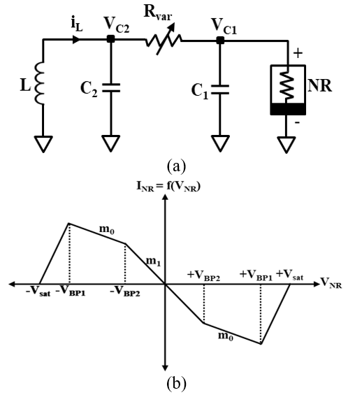
Developed by Leon O. Chua in 1983, the standard Chua circuit of Figure 1(a) is among the most widely recognized chaotic circuit models. Chaotic behavior requires the circuit to contain three kinds of elements: (i) at least one nonlinear element, (ii) at least one locally active resistor, and (iii) at least three energy storage elements [10]. The appeal of Chua's circuit lies in the wide variety of attractors it can display, ranging from small limit cycles to long-period orbits [22]. As shown in Figure 1(a), the standard circuit comprises one non-linear negative resistor (NR), one inductor (L), two capacitors (C1 and C2), and one variable resistor (Rvar). The NR, commonly called the Chua diode, is central to the non-linear behavior of the circuit. Figure 1(b) presents the five-segment piecewise-linear I-V characteristic of the Chua diode, illustrating its piecewise-linear negative-resistance property. Conventionally, Chua's diode has been formed by combining two voltage-dependent negative resistors [1]. Chaotic oscillators have received considerable attention because of their roles in secure communications, random number generation, and nonlinear dynamics. Conventional Chua circuit designs, although functional, are constrained by a limited frequency range and inefficient use of components. Progress in active elements, especially the VDCC, opens new possibilities for improving circuit performance. This paper proposes a high-efficiency VDCC-based Chua's circuit that addresses these limitations, and the approach is compared with existing methods to highlight gains in frequency performance, power efficiency, and component count.
Figure 1. Standard Chua circuit (a) circuit diagram and (b) I-V characteristics
Because the proposed Chua circuit adopts VDCC ABBs as the active elements, this section begins with an overview of the VDCC. The nonlinear resistors, NR1 and NR2, are then described, followed by Chua's diode, which governs the nonlinear behavior of the chaotic oscillator. The final subsection presents the simulated inductor circuit that replaces a bulky physical inductor in Chua's circuit.
3.1 Voltage differencing current conveyor
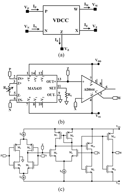
The VDCC is a five-terminal ABB, and its electrical symbol appears in Figure 2(a). Terminals P and N act as high-impedance inputs, terminals Z and W serve as high-impedance outputs, and terminal X operates as a low-impedance output. The voltage and current relationships among these terminals are summarized in Eq. (1).
$\begin{gathered}I_P=I_N=0 \\ I_z=g_m\left(V_P-V_N\right) \\ V_X=V_Z \\ I_{W+}= \pm I_X\end{gathered}$ (1)
Eq. (1) leads to the following observations: the currents entering the P and N terminals are zero because of their high impedance; the current at the Z terminal equals the transconductance gain (gm) multiplied by the differential input voltage (VP-VN); the voltage at the Z terminal is conveyed to the X terminal; and the current at the X terminal is conveyed to the W terminal. Figure 2(b) shows one possible VDCC implementation based on the ICs MAX435 and AD844, while Figure 2(c) presents a CMOS schematic of the VDCC. Both implementations are used later in the simulations of the proposed circuits.
Figure 2. Voltage differencing current conveyor (VDCC), (a) an electrical symbol, (b) implementation using ICs and (c) a CMOS schematic
3.2 Chua's diode using voltage differencing current conveyor
Chua's diode is a non-linear negative resistance (NR) exhibiting negative piecewise-linear characteristics. Its implementation typically requires two NRs (NR1 and NR2). Accordingly, the designs of NR1 and NR2 are presented first, followed by the design of the NR itself.
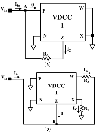
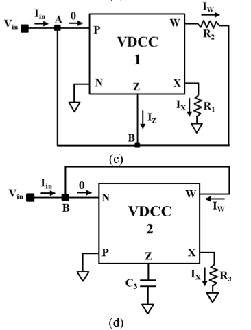
Figure 3. Design of negative resistances, Chua diode, and simulated inductor using voltage differencing current conveyor (VDCC): (a) NR1, (b) NR2, (c) Chua diode and (d) simulated inductor
Design of NR1: Figure 3(a) shows NR1 realized with a single VDCC and one resistor. For given values of transconductance (gm) and resistance (R1), the theoretical inner slope (m11), outer slope (m01), and breakpoints (VBP) of NR1 can be predicted from their analytical expressions, which are derived as follows.
Applying KCL at node A in Figure 3(a) and invoking the VDCC terminal relationship in Eq. (1) yields the inner slope (m11) as:
$m_{11}=\frac{I_{i n}}{V_{i n}}=-g_m$ (2)
The input current $I_{\text {in}}$ of Figure 3(a) can be expressed when VDCC operates in the saturation region as:
$I_{i n}=\frac{V_{i n}-V_Z}{R_A}=\frac{V_{i n}}{R_A}-\frac{V_Z}{R_A}=\frac{V_{i n}}{R_A}-\frac{ \pm V_{s a t}}{R_A}$ (3)
Here, it can be observed that Eq. (3) represents the equation of straight lines in the outer region having a slope of $m_{01}$.
Hence, $m_{01}=\frac{1}{R_A}$ (4)
Applying KVL to Figure 3(a) then gives the breakpoint at the boundary of the saturation regions as:
$\pm V_{B P 1}=\frac{ \pm V_{s a t}}{1+g_m R_A}$ (5)
The resistor RA of NR1 is omitted in the proposed Chua's diode design, i.e., RA = 0 (short circuit), because one of the NRs in Chua's diode always remains in the linear region.
For $R_A=0$, the Outer Slope $\left(m_{01}\right)$ and Breakpoint $\left( \pm V_{B P 1}\right)$, given in Eqs. (4) and (5), respectively, can be expressed as: $m_{01} \approx$ $\infty$ and $\pm V_{B P 1}= \pm V_{\text {sat}}$.
Design of NR2: Figure 3(b) depicts NR2 constructed from one VDCC and two resistors. The theoretical expressions for the inner slope (m12), outer slope (m02), and breakpoints (VBP) of NR2 for given values of transconductance (gm) and resistances (R1 and R2) are derived below.
Applying KCL at node B in Figure 3(b) together with the VDCC terminal relationship in Eq. (1) gives the inner slope of NR2 (m12) as:
$m_{12}=\frac{I_{i n}}{V_{i n}}=\frac{-1}{R_2}$ (6)
The input current $I_{\text {in}}$ of Figure 3(b) can be expressed when VDCC operates in the saturation region as:
$I_{i n}=\frac{V_{i n}-V_w}{R_2}=\frac{V_{i n}}{R_2}-\frac{V_w}{R_2}=\frac{V_{i n}}{R_2}-\frac{ \pm V_{s a t}}{R_2}$ (7)
Here, it can be observed that Eq. (7) represents the equation of straight lines in the outer region having a slope of m02.
$m_{02}=\frac{1}{R_A}$ (8)
Applying KVL to Figure 3(b) and rearranging the resulting equation at the boundary of the saturation regions yields the breakpoint of NR2 as:
$\pm V_{B P 2}=\frac{ \pm V_{\text {sat }}}{1+\frac{R_2}{R_1}}$ (9)
Design of Chua diode/NR: A new non-linear Chua's diode is now obtained by suitably combining NR1 and NR2, as illustrated in Figure 3(c).
Applying KCL at node B in Figure 3(c) and using the VDCC terminal relationship in Eq. (1), the inner slope (m1) of the proposed Chua diode becomes:
$m_1=\frac{I_{i n}}{V_{i n}}=-g_m-\frac{1}{R_2}=m_{11}+m_{12}$ (10)
Similarly, the input current Iin of Figure 3(c) within the saturation region takes the form:
$I_{i n}=\left(-g_m+\frac{1}{R_2}\right) V_{i n}-\frac{ \pm V_{s a t}}{R_2}$ (11)
Here, it can be observed that Eq. (11) is the equation of a straight line having an outer slope of $m_o$.
$m_o=-g_m+\frac{1}{R_2}$ (12)
Combining Eqs. (2), (8), and (12), the outer slope of Chua's diode becomes:
$m_o=m_{11}+m_{o 2}$ (13)
Design of a grounded simulated inductor: Figure 3(d) presents a grounded simulated inductor built from a single VDCC together with one grounded resistor and one grounded capacitor. Routine analysis of Figure 3(d) gives the input impedance (Zin) of the circuit as:
$Z_{\text {in }}=\frac{V_{\text {in}}}{I_{\text {in}}}=\frac{s R_3 C_3}{g_m}$ (14)
Eq. (14) then gives the equivalent inductance (Leq) of the circuit as:
$Z_{\text {in }}=\frac{V_{\text {in}}}{I_{\text {in}}}=\frac{s R_3 C_3}{g_m}$ (15)
3.3 Design of Chua's circuit
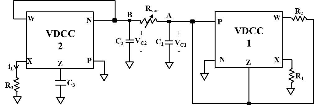
The standard Chua's circuit of Figure 1(a) is realized here with VDCCs, and the resulting VDCC-based circuit appears in Figure 4. It employs the proposed VDCC-based Chua's diode of Figure 3(c) together with the VDCC-based grounded simulated inductor of Figure 3(d). A variable resistor, Rvar, tunes the circuit to produce different attractors. The chaotic outputs consist of the voltage signals VC1 and VC2 and the current signal iL. Notably, the inductor current, iL, is available at a separate terminal X of VDCC-2.
Figure 4. Proposed Chua's chaotic circuit using voltage differencing current conveyor (VDCC)
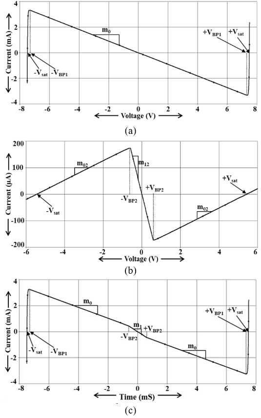
PSPICE software is used to simulate the proposed Chua's diode and circuit, employing macro-models of commercially available ICs as well as TSMC 180nm CMOS technology. The VDCC, acting as the active block, is first realized with ICs, as illustrated in Figure 2(b), where the two ICs MAX435 and AD844 are combined to form the VDCC. The MAX435 is a high-performance dual-output OTA IC, while the AD844 is a CFOA IC. In the IC-based VDCC simulation, both ICs are powered with VDD = +15 V and VSS = -15 V. The resistor RB of the MAX435 is set to 8.8kΩ, fixing the transconductance gain at gm = 455 µA/V through the relation gm = 4/RB, while RA is set to 20kΩ to establish the proper supply current of the MAX435. The NR1 (Figure 3(a)), NR2 (Figure 3(b)), and NR (Figure 3(c)) circuits are then built with the IC-based VDCC, and DC sweep analysis produces their I-V characteristics, which are plotted in Figure 5. The curves follow the theoretically expected trajectories. To quantitatively verify the design, Table 1 compares the theoretical parameters calculated from Eqs. (10), (12), and (19) against the simulated I-V characteristics obtained from Figure 5. The close agreement (within 3.3% error) confirms the analytical derivations.
Figure 5. Voltage-Current characteristics of (a) NR1, (b) NR2 and (c) Chua diode
The proposed Chua circuit of Figure 4 is then simulated with the IC-based VDCC to obtain the transient response. With Rvar fixed at 1700 Ω, the expected chaotic waveforms, VC1, VC2, and iL, are successfully generated, as displayed in Figures 6(a)-(c), respectively. The passive component values in this simulation are C1 = C3 = 1 nF, C2 = 10 nF, R1 = 3.3 kΩ, R2 = 27 kΩ, and R3 = 0.82 kΩ. To identify the dominant operating frequency, the FFT of the VC2 waveform is examined in Figure 6(d), which indicates a dominant frequency of 25.8 kHz for the IC-based circuit.
By varying Rvar in the same IC-based simulation, several chaotic attractors are obtained, including a large limit cycle, double-scroll, Rossler-type, and I-periodic attractors, as presented in Figure 7. These attractors are captured from the transient sweep by plotting VA against VB.
Table 1. Quantitative comparison between theoretical and simulated parameters of the proposed Chua diode
|
Parameter |
Analytical Expression |
Component Used |
Theoretical Value |
Simulated Value (From Figure 5) |
Relative Error (%) |
|
Inner Slope (m1) |
$-g_m-\frac{1}{R_2}$ |
$g_m$ = 455 µA/V, R2 =27 kΩ |
-492.04 µA/V |
-481.50 µA/V |
2.14% |
|
Outer Slope (m0) |
$-g_m+\frac{1}{R_2}$ |
$g_m$ = 455 µA/V, R2 = 27 kΩ |
-417.96 µA/V |
-409.20 µA/V |
2.10% |
|
Breakpoint (VBP1) |
$\pm V_{\text {sat}}$ |
$\pm V_{\text {sat}}=$ = 7.5 V |
±7.50 V |
±7.46 V |
0.53% |
|
Breakpoint (VBP2) |
$\frac{ \pm V_{\text {sat}}}{1+\frac{R_2}{R_1}}$ |
$\pm V_{\text {sat}}=$ = 7.5 V, R1 = 3.3 kΩ, R2 = 27 kΩ |
±0.817 V |
±0.800 V |
2.08% |
Figure 6. Chaotic waveforms and FFT (a) VA, (b) VB, (c) IL and (d) FFT of VB
Figure 7. Simulated attractors of the IC-based Chua's circuit (a) Large limit cycle at Rvar = 1500 Ω, (b) Double-scroll attractor at Rvar = 1600 Ω, (c) Double-scroll attractor at Rvar = 1700 Ω, (d) Double-scroll attractor at Rvar = 1850 Ω, (e) Rossler-type attractor at Rvar = 1885 Ω, and (f) I-periodic attractor at Rvar = 1940 Ω
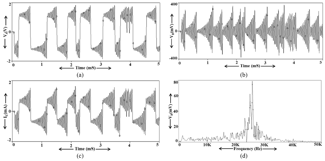
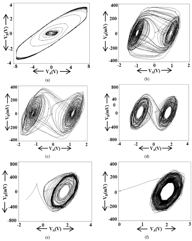
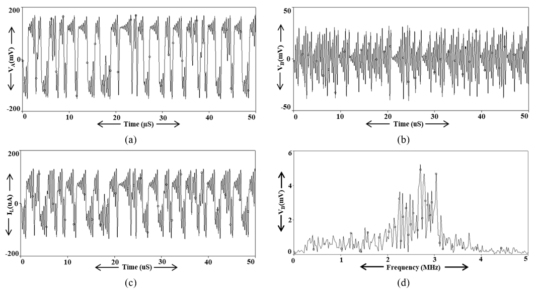
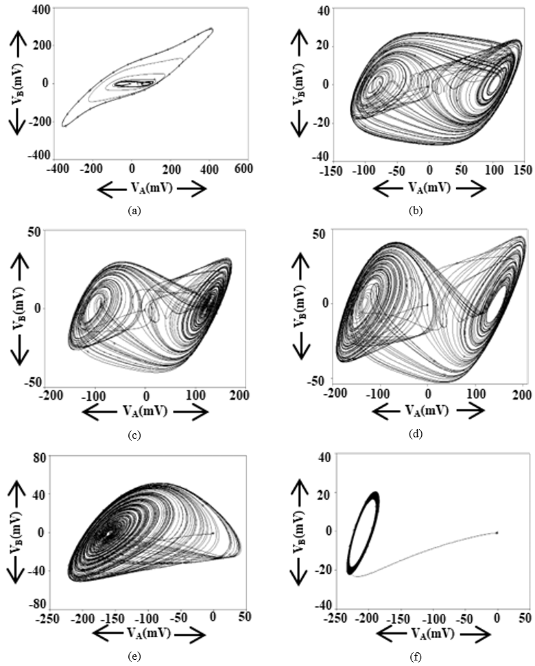
The Chua circuit of Figure 4 is subsequently simulated with the CMOS realization of the VDCC (shown in Figure 2(c)) in TSMC 180 nm CMOS technology. Table 2 lists the widths and lengths of the MOSFETs used in Figure 2(c). A supply of ±0.9 V is applied for proper biasing of the circuit. With bias currents set to I1 = I2 = I3 = 50 µA, the simulated transconductance gain of the input differential pair is gm = 458.20 µA/V. The passive elements in this simulation are C1 = C3 = 10 pF, C2 = 100 pF, R1 = 3.3 kΩ, R2 = 27 kΩ, and R3 = 0.82 kΩ. Because all three capacitor values are scaled down by a factor of one hundred relative to the IC-based case, the chaotic waveforms VA, VB, and IL of Figure 8 evolve much faster. The FFT of the chaotic voltage at node B, shown in Figure 8(d), reveals a dominant operating frequency of 2.7 MHz. Varying Rvar again produces multiple chaotic attractors, shown in Figure 9, confirming that the proposed circuit sustains chaotic signal generation.
Table 2. Width (W) and Length (L) of MOSFETs used in Figure 2(c)
|
MOSFET |
M1-M2 |
M3-M4 |
M5-M6 |
M7-M8 |
M9, M11 |
M10, M12 |
|
W (µm) |
3.6 |
16.64 |
3.06 |
9 |
14.4 |
0.72 |
|
L (µm) |
0.36 |
0.36 |
0.72 |
0.72 |
0.72 |
0.72 |
Figure 8. Chaotic waveforms and FFT (a) VA, (b) VB, (c) IL and (d) FFT of VB
Figure 9. Simulated attractors of the CMOS-based Chua's circuit (a) Large limit cycle at Rvar = 1500 Ω, (b) Double-scroll attractor at Rvar = 1600 Ω, (c) Double-scroll attractor at Rvar = 1700 Ω, (d) Double-scroll attractor at Rvar = 1850 Ω, (e) Rossler-type attractor at Rvar = 1885 Ω, and (f) I-periodic attractor at Rvar = 1940 Ω
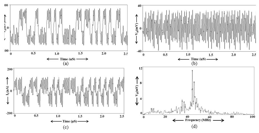
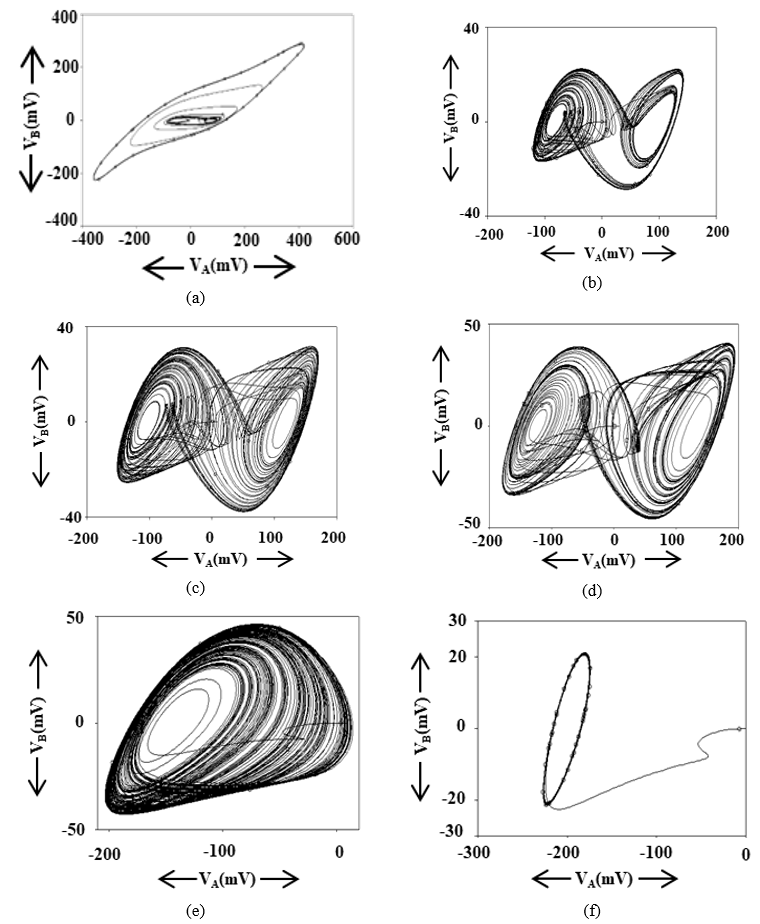
Simulations of the proposed circuit with the CMOS implementation of the VDCC further show that scaling down the capacitors C1, C2, and C3 in Figure 4 raises the frequency of the generated chaotic signals. Sustainable chaotic signals at the highest frequency of 44.4 MHz are obtained by selecting the capacitor values as C1 = 0.5 pF, C2 = 5 pF, and Leq = 1.4 µH. The resulting high-frequency chaotic waveforms (VA, VB, and IL) and the FFT of VB are depicted in Figure 10. The FFT plot of the VB waveform in Figure 10(d) confirms the highest dominant operating frequency of 44.4 MHz, and Figure 11 shows the corresponding chaotic attractors of this fast circuit.
Figure 10. Chaotic voltage and current waveforms and FFT (a) VA, (b) VB, (c) IL and (d) FFT of VB
Figure 11. Simulated attractors of the CMOS-based high-frequency Chua's circuit (a) Large limit cycle at Rvar = 1500 Ω, (b) Double-scroll attractor at Rvar = 1600 Ω, (c) Double-scroll attractor at Rvar = 1700 Ω, (d) Double-scroll attractor at Rvar = 1800 Ω, (e) Rossler-type attractor at Rvar = 1900 Ω, (f) I-periodic attractor at Rvar = 2270 Ω
This section examines how the non-ideal characteristics of the active element influence the performance of the proposed Chua's circuit. Since the VDCC serves as the active element, the consequences of its non-idealities deserve careful attention. Two main sources of non-ideality are considered: gain errors and parasitic impedances at the various ports of the VDCC.
5.1 Non-ideality due to gain errors
Gain errors appear in the transconductance gain, voltage gain, and current gain of the VDCC. Their coefficients are denoted α for the voltage gain, β for the transconductance gain, and γ for the current gain, each ideally equal to unity. Including these non-idealities transforms the VDCC port relationship of Eq. (1) into:
$\begin{gathered}I_P=I_N=0 ; I_z=\beta_1 g_m\left(V_P-V_N\right) ; \\ V_X=\alpha V_Z ; I_{W \pm}= \pm \gamma I_X\end{gathered}$ (16)
The analysis now turns to Chua's diode, the central element of Chua's circuit, and to the simulated inductor. To evaluate the effect of the various gain errors on the proposed circuit, Chua's diode and the simulated inductor are analyzed with the modified VDCC port relationship given in (16). Routine analysis of the diode in Figure 3(c) produces the modified inner slope m1(NI), outer slope m0(NI), and breakpoints VBP1(NI), which are stated in Eqs. (17)–(19), respectively.
Innerslope:
$m_{1(N I)}=-\beta_1 g_m-\frac{\alpha \gamma}{R_1}$ (17)
Outerslope:
$m_{o(N I)}=-\beta_1 g_m+\frac{1}{R_2}$ (18)
Breakpoints:
$\pm V_{B P 1}= \pm V_{s a t} ; \pm V_{B P 2}=\frac{\pm V_{s a t}}{1+\frac{\alpha \gamma R_2}{R_1}}$ (19)
Inspection of Eqs. (17)–(19) shows that the gain errors introduce noticeable deviations in the parameters of Chua's diode. By applying linearized nodal analysis around the origin, the resulting characteristic equation becomes:
$\begin{gathered}s^3 C_1 C_2 L_{e q}+s^2\binom{C_1 L_{e q} G_{v a r}+}{C_2 L_{e q}\left(G_{v a r}+m_1(N I)\right)} \\ +s\left(L_{e q} G_{v a r} m_1(N I)+C_1+C_2\right)+G_{v a r}+m_1(N I)=0\end{gathered}$
where, $G_{v a r}=1 / R_{v a r}$ and $m_1(N I)=-\beta_1 g_m-\frac{\alpha \gamma}{R_2}$. This shows that deviations in $\alpha, \beta, \gamma$ slightly shift the condition of oscillation and the frequency of oscillation, but can be easily compensated for in practice by adjusting $R_{\text {var}}$.
As a result, the Condition of Oscillation (CO) and the Frequency of Oscillation (FO) of the circuit are also influenced. These deviations remain small, however, because the simulated values of α, β, and γ are close to unity.
The gain errors are additionally frequency-dependent, and the high-frequency operation of Chua's circuit requires these frequency-dependent effects to be considered. Using a single-pole model, the VDCC gain errors, α(s), β(s), and γ(s), are defined as:
$\alpha(s)=\frac{\alpha_0}{1+\frac{s}{\omega_\alpha}} ; \beta(s)=\frac{\beta_0}{1+\frac{s}{\omega_\beta}} ; \beta(s)=\frac{\gamma_0}{1+\frac{s}{\omega_\gamma}}$ (20)
Here, α₀, β₀, and γ₀ denote the DC gain errors, while ωα, ωβ, and ωγ are the corresponding first-order pole frequencies, whose practical values depend on the internal architecture of the VDCC.
5.2 Non-ideality due to parasitic impedances of voltage differencing current conveyor
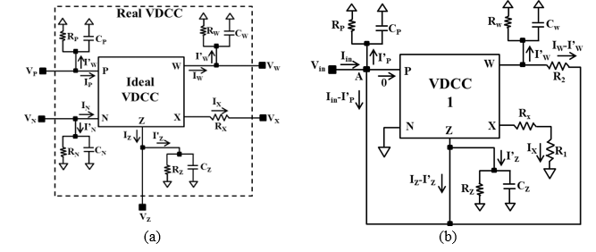
The second non-ideality arises from parasitic impedances at the various ports of the VDCC, as illustrated in Figure 12(a). These parasitics can alter the behavior of both Chua's diode and the simulated inductor, and hence of the overall proposed circuit. Figure 12(b) shows Chua's diode with the parasitic impedances included.
Figure 12. Presence of parasitic impedances on (a) voltage differencing current conveyor (VDCC) and (b) proposed Chua diode
To quantify the influence of the parasitic impedances on Chua's diode, expressions for its inner slope, outer slope, and breakpoints in the presence of parasitics are derived as follows:
By the routine analysis of Figure 12(b), the inner slope $\left(m_{1(P I)}\right)$ and outer slope $\left(m_{o(P I)}\right)$ of the proposed Chua diode, including parasitic, can be expressed as:
$\begin{gathered}m_{1(P I)}=\frac{I_{i n}}{V_{i n}}=-\left(g_m+\frac{1}{R_1+R_X}\right) +\left(\frac{1}{R_P}+S C_P+\frac{1}{R_Z}+S C_z\right) \\ +\frac{\left(\frac{1}{R_1+R_X}+\frac{1}{R_2}\right)\left(\frac{1}{R_W}+S C_W\right)}{\left(\frac{1}{R_2}+\frac{1}{R_W}+S C_W\right)}\end{gathered}$ (21)
$m_{o(P I)}=-g_m+\frac{1}{R_2}+\frac{1}{R_P}+s C_P+\frac{1}{R_Z}+s C_Z$ (22)
The breakpoints, VBP1 and VBP2, of the Chua diode with parasitic impedances are similarly obtained as follows:
$\left.\begin{array}{c} \pm V_{B P 1(P I)}= \pm V_{\text {sat }} \\ \pm V_{B P 2(P I)}=\frac{ \pm V_{\text {sat }}}{1+\frac{R_2}{R_1+R_x}}\end{array}\right\}$ (23)
From the expressions of $m_{1(P I)}, m_{0(P I)}, \pm V_{B P 1(P I)}$, and $\pm V_{B P 2(P I)}$, given in Eqs. (21)–(23), respectively, it can be observed that the VDCC-based Chua diode is affected by the parasitic impedances of the VDCC. However, for the simulated values of the parasitic impedance, given in the simulation section, the impacted expressions, given in Eqs. (21)–(23), can be approximated to the real expressions of the inner-slope, outer-slope, and breakpoints of the Chua diode without parasitic impedances.
The proposed Chua circuit is benchmarked against comparable implementations from the existing literature. Several key parameters are examined, including the number of active and passive components, the fabrication technology, the supply voltage, and the highest dominant operating frequency. Table 3 clearly shows the advantage of the proposed design in terms of higher operating frequency, fewer components, and better power efficiency. The dominant operating frequency of 44.4 MHz achieved here is well above the highest value reported in earlier works [17]. The combination of VDCCs and simulated inductors underlies this improvement by extending the frequency range and lowering power consumption. The comparison confirms that the proposed design surpasses state-of-the-art implementations and resolves key limitations such as a narrow frequency range and high power consumption.
Table 3. Comparison with existing Chua circuit implementations
|
Ref., Year |
No. of ABBs Used |
No. of PCs Used (R + L + C) |
Technology Used |
Supply Voltage (Volts) |
Inductorless Implementation |
Separate Terminal for Inductor Current |
Highest Dominant Operational Frequency |
|
[26], 2011 |
3, OA & 2, diode |
13R + 3C |
BJT-based IC |
±15 |
YES |
NO |
NA |
|
[27], 2011 |
3, OA & 6, diode |
12R + 3C |
BJT-based IC |
±15 |
YES |
NO |
5 kHz |
|
[28], 2014 |
2, CFOA |
8R + 3C |
BJT-based IC |
NA |
YES |
NO |
1.03MHz |
|
[29], 2016 |
3, DVCCTA |
6R + 3C |
CMOS 0.25µm |
±15 |
YES |
NO |
NA |
|
[30], 2016 |
3, OTRA |
10R + 4C |
CMOS 0.5µm |
NA |
YES |
NO |
NA |
|
[31], 2017 |
11, CCII |
19R + 3C |
BJT-based IC |
NA |
NA |
NO |
910 kHz & 65 kHz |
|
[14], 2020 |
1, VDTA |
2R + 1L + 2C |
CMOS 0.18 µm |
±0.9 |
NO |
NO |
20MHz |
|
[15], 2022 |
2, VDGA |
3C |
CMOS 0.18µm |
±0.9 |
YES |
NO |
21.1MHz |
|
[16], 2023 |
1, EXCCCII |
1R + 1L + 2C |
CMOS 0.25µm |
±1.25 |
NO |
NO |
NA |
|
[17], 2024 |
1, CCTA |
3R + 1L + 2C |
CMOS 0.18µm |
±0.9 |
NO |
NO |
37.5MHz |
|
[18], 2025 |
2, DXCCII |
6R + 3C |
CMOS 0.18µm |
±0.9 |
YES |
NO |
NA |
|
Proposed work |
2, VDCC |
3C + 3R + 1Rvar |
CMOS 0.18µm |
±0.9 |
YES |
YES |
44.4MHz |
*ABBs: Active Building Blocks; *PCs: Passive Components, *NA: Not Available
A novel, high-efficiency VDCC-based design of Chua's circuit has been presented, delivering strong performance for high-frequency chaotic oscillation. The design overcomes major shortcomings of existing methods and offers practical benefits in power efficiency and component count. The work introduces an innovative VDCC-based Chua's diode together with a high-speed Chua's circuit. Careful PSPICE simulations with MAX435 and AD844 IC macro-models and TSMC 0.18µm CMOS technology capture the non-linear characteristics of Chua's diode under DC sweep analysis. Replacing physical inductors with simulated counterparts improves manufacturability without sacrificing performance. The chaotic waveforms and attractors observed in simulation firmly confirm the circuit's ability to generate chaotic dynamics. The design attains substantial speed gains and an extended frequency spectrum, reaching a dominant operating frequency of 44.4 MHz. Comparative analysis with the existing literature underscores the superior performance of the proposed configuration. Future work will focus on experimental chip fabrication, layout-level post-layout simulations, and integrating this high-frequency chaotic core into hardware encryption and random number generation modules.
The authors thank the anonymous reviewers for their valuable suggestions, which improved the quality of the manuscript. This work is supported by Telkom University PPM (Grant number: 056/LIT06/PPM-LIT/2025).
[1] Donoghue, K.O., Kennedy, M.P., Forbes, P., Qu, M., Jones, S. (2005). A fast and simple implementation of Chua’s oscillator with “cubic-like” nonlinearity. International Journal of Bifurcation and Chaos, 15(9): 2959-2971. https://doi.org/10.1142/S0218127405013800
[2] Elwakil, A.S., Kennedy, M.P. (2000). Improved implementation of Chua’s chaotic oscillator using current feedback op amp. IEEE Transactions on Circuits and Systems I: Fundamental Theory and Applications, 47(1): 76-79. https://doi.org/10.1109/81.817395
[3] Sprott, J.C. (2011). A new chaotic jerk circuit. IEEE Transactions on Circuits and Systems II: Express Briefs, 58(4): 240-243. https://doi.org/10.1109/TCSII.2011.2124490
[4] Nguenjou, L.P.N., Kom, G.H., Pone, J.R.M., Kengne, J., Tiedeu, A.B. (2019). A window of multistability in Genesio-Tesi chaotic system, synchronization and application for securing information. AEU - International Journal of Electronics and Communications, 99: 201-214. https://doi.org/10.1016/j.aeue.2018.11.033
[5] Vaidyanathan, S., Volos, C. (2016). Advances and Applications in Chaotic Systems (1st ed.). Springer International Publishing.
[6] Rincu, C.I., Iana, V.G. (2007). Aspects regarding chaotic maps hardware implementations. Revue Roumaine des Sciences Techniques – Électrotechnique et Énergétique, 52(2): 219-227.
[7] Chua, L.O., Komuro, M., Matsumoto, T. (1986). The double scroll family. IEEE Transactions on Circuits and Systems, 33(11): 1072-1118. https://doi.org/10.1109/TCS.1986.1085869
[8] Aguilar-López, R., Mata-Machuca, J.L. (2023). Stabilization of a chaotic oscillator via a class of integral controllers under input saturation. Scientific Reports, 13: 5927. https://doi.org/10.1038/s41598-023-33201-3
[9] Petrzela, J. (2024). Chaotic systems based on higher-order oscillatory equations. Scientific Reports, 14: 72034. https://doi.org/10.1038/s41598-024-72034-6
[10] Kennedy, M.P. (1992). Robust op-amp realization of Chua’s circuit. Frequenz, 46(3-4): 66-80. https://doi.org/10.1515/FREQ.1992.46.3-4.66
[11] Li, H., Liu, J., Li, C., Du, L. (2024). Vibrational resonance and chaos control in the canonical Chua’s circuit with a smooth nonlinear resistor. Scientific Reports, 14: 31013. https://doi.org/10.1038/s41598-024-82250-9
[12] Lee, W., Kim, H., Jung, H., Choi, Y., Jeon, J., Kim, C. (2025). Correlation-free large-scale probabilistic computing using a true-random chaotic oscillator p-bit. Scientific Reports, 15: 8018. https://doi.org/10.1038/s41598-025-93218-8
[13] Choubey, C.K., Paul, S.K. (2020). Implementation of chaotic oscillator by designing a simple Chua's diode using a single VDTA. AEU - International Journal of Electronics and Communications, 124(11): 1-15. https://doi.org/10.1016/j.aeue.2020.153360
[14] Choubey, C.K., Paul, S.K. (2022). Systematic realisation of inductorless and resistorless Chua's chaotic oscillator using VDGA. International Journal of Electronics, 110(6): 1006-1027. https://doi.org/10.1080/00207217.2022.2068200
[15] Bhatt, V., Ranjan, A., Singh, Y.S. (2022). Resistorless Chua's diode implementation for chaotic oscillation employing single EXCCCII. AEU - International Journal of Electronics and Communications, 156: 154398. https://doi.org/10.1016/j.aeue.2022.154398
[16] Choubey, C.K., Pathak, A., Tiwari, M.K. (2024). A method to design a fast chaotic oscillator using CCTA. MethodsX, 13: 102801. https://doi.org/10.1016/j.mex.2024.102801
[17] Choubey, C.K., Gupta, A., Pathak, A. (2025). Design methodology for low-power, low-voltage inductor-less Chua's chaotic oscillator. MethodsX, 14: 103365. https://doi.org/10.1016/j.mex.2025.103365
[18] Güney, A., Kuntman, H., Kaçar, F. (2021). CMOS realization of electronically tunable VDCC based single-input–dual-output filter. AEU - International Journal of Electronics and Communications, 132: 153627. https://doi.org/10.1016/j.aeue.2021.153627
[19] Arena, P., Baglio, S., Fortuna, L., Manganaro, G. (1995). Chua’s circuit can be generated by CNN cells. IEEE Transactions on Circuits and Systems I, 42(2): 123-125. https://doi.org/10.1109/81.372854
[20] Morgül, O. (1995). Inductorless realization of Chua oscillator. Electronics Letters, 31(17): 1403-1404. https://doi.org/10.1049/el:19950975
[21] Senani, R., Gupta, S. (1998). Implementation of Chua’s chaotic circuit using current feedback op-amp. Electronics Letters, 34(9): 829-830. https://doi.org/10.1049/el:19980621
[22] Torres, L.A.B., Aguirre, L.A. (2000). Inductorless Chua’s circuit. Electronics Letters, 36(23): 1915-1916. https://doi.org/10.1049/el:20001363
[23] Gandhi, G. (2006). An improved Chua’s circuit and its use in hyperchaotic circuit. Analog Integrated Circuits and Signal Processing, 46: 173-178. https://doi.org/10.1007/s10470-005-0376-0
[24] Tlelo-Cuautle, E., Gaona-Hernández, A., García-Delgado, J. (2006). Implementation of a chaotic oscillator by designing Chua's diode with CMOS CFOAs. Analog Integrated Circuits and Signal Processing, 48: 159-162. https://doi.org/10.1007/s10470-006-7299-2
[25] Kilic, R. (2006). Experimental study on impulsive synchronization between two modified Chua's circuits. Nonlinear Analysis: Real World Applications, 7(5): 1298-1303. https://doi.org/10.1016/j.nonrwa.2005.12.004
[26] Gopakumar, K., Premlet, B., Gopchandran, K.G. (2011). Implementation of Chua's circuit using simulated inductance. International Journal of Electronics, 98(5): 667-677. https://doi.org/10.1080/00207217.2010.520151
[27] Gopakumar, K., Premlet, B., Gopchandran, K.G. (2011). Chua's oscillator in integrated circuit form with inbuilt control option. Journal of Circuits, Systems and Computers, 20(8): 1591-1604. https://doi.org/10.1142/S0218126611008079
[28] Jothimurugan, R., Suresh, K., Ezhilarasu, P.M., Thamilmaran, K. (2014). Improved realization of canonical Chua's circuit with simulated inductor using current feedback operational amplifiers. AEU - International Journal of Electronics and Communications, 68(5): 413-421. https://doi.org/10.1016/j.aeue.2013.11.004
[29] Kushwaha, A.K., Paul, S.K. (2016). Inductorless realization of Chua's oscillator using DVCCTA. Analog Integrated Circuits and Signal Processing, 88(1): 137-150. https://doi.org/10.1007/s10470-016-0746-9
[30] Kushwaha, A.K., Paul, S.K. (2016). Chua's oscillator using operational transresistance amplifier. Revue Roumaine des Sciences Techniques – Électrotechnique et Énergétique, 61(3): 299-303.
[31] Li, Z., Ma, M., Wang, M., Zeng, Y. (2017). Realization of current-mode SC-CNN-based Chua's circuit. AEU - International Journal of Electronics and Communications, 71: 21-29. https://doi.org/10.1016/j.aeue.2016.11.003