Adrián Rodríguez* | Omar J. Tafur | Christian V. Rodriguez | Gustavo O. Guarniz Avalos
© 2026 The authors. This article is published by IIETA and is licensed under the CC BY 4.0 license (http://creativecommons.org/licenses/by/4.0/).
OPEN ACCESS
The hydraulic behaviour of a centrifugal pump is strongly conditioned by the geometry of its impeller, particularly by the shape of the blade trailing edge. This study examines how alternative trailing-edge configurations affect the hydraulic head delivered by the Grundfos NB 80-250/270 pump. The original geometry was modeled in Autodesk Inventor, and mesh independence and validation tests were carried out in ANSYS Fluent using the SST k-ω turbulence model. The numerical predictions showed an average deviation of 2.586% from experimental data, demonstrating good agreement between the numerical and experimental results. After validation, three modified trailing-edge profiles: sinusoidal, rectangular, and trapezoidal, were analysed. The results indicate that, under low-flow conditions (≤20 m³/h), all modified geometries produce a higher hydraulic head than the original design, with the sinusoidal profile yielding the greatest increase (5.86% at 10 m³/h). At moderate flow rates, the trapezoidal configuration improves performance by 2.17% at 40 m³/h. However, at higher flow rates (>60 m³/h), the unmodified impeller retains the best hydraulic response. These findings show that smooth geometric adjustments at the blade exit can enhance energy transfer when the pump operates at low flow, suggesting opportunities for targeted optimization of impeller profiles based on specific operating requirements.
centrifugal pump, computational fluid dynamics, impeller, blade trailing edge, hydraulic head
The purpose of centrifugal pumps is to transform the mechanical energy transmitted by the shaft into hydraulic energy, expressed in terms of fluid pressure and velocity, which ultimately results in the pump head [1]. In this process, the impeller becomes the key component of the system, particularly due to the number of blades and the angular arrangement of their outlet, since these parameters directly influence the transfer of energy to the fluid [2]. The study of the rotor in a centrifugal pump is therefore crucial for improving its hydraulic performance and ensuring maximum efficiency during operation. In this context, computational fluid dynamics (CFD) has become an essential tool for modeling and predicting flow behavior within rotating machines, allowing the evaluation of flow structures, pressure distributions, and the effects of geometric variations and operating conditions [3, 4]. In the study of Wang et al. [5], an integrated CFD-based optimization platform was recently developed, merging parametric modeling, automatic mesh generation, Kriging surrogate models, and multi-objective genetic algorithms to simultaneously improve the hydraulic design of a centrifugal pump. According to the authors, the geometric variables with the greatest impact on efficiency and hydraulic head are the number of vanes and the volute throat size. They also experimentally verified the simulations through hydraulic tests and Particle Image Velocimetry (PIV) measurements, achieving discrepancies of less than 10% between the experimental and numerical data, thus demonstrating the reliability of CFD as a tool for optimizing and designing centrifugal pumps.
One of the most influential variables in centrifugal pump design is the blade exit angle of the rotor. This parameter determines the flow direction at the impeller outlet and consequently affects the internal velocity and pressure distributions. Several studies have demonstrated that the blade design angle significantly influences the fluid velocity profile as well as the overall efficiency and stability of the system. In the study of Sakran et al. [6], it was determined that an impeller exit angle of 15° contributed to reducing structural stresses, load fluctuations, and the shaft power requirement, estimated at 3945 W, achieving a pump efficiency of 84%. Similarly, Sakran et al. [7] showed that the blade exit angle influences entropy generation and the interaction of fluid structures, which may alter velocity distribution and lead to operational instabilities. Another study demonstrated that as the blade wrap angle increases from 85° to 125°, the pump head tends to decrease, while the efficiency increases by approximately 4.2% to 11.1% [2]. In the study of Susilo and Setiawan [8], three impeller blade exit angles of 130°, 150°, and 160° were proposed. For the 130° configuration, the pressure increased from 0.45 to 2.45 bar; for the 150° angle, it increased from 0.14 to 2.96 bar; and for the 160° angle, the pressure increased from 0.29 to 3.07 bar. In another investigation [9], exit angles of 16°, 20°, 24°, 28°, and 32° were analysed, concluding that an exit angle of 16° provided the best anti-cavitation flow field and improved efficiency by 3%. These studies indicate that changes in the rotor exit angle are associated with an increase in hydraulic efficiency, since larger angles tend to reduce internal friction losses and promote better flow adaptation to the blade contour.
In addition to the exit angle, other geometric characteristics of the impeller such as blade thickness, blade length, and trailing-edge geometry play a fundamental role in pump performance. Several studies have demonstrated that modifying blade geometry can improve hydraulic performance by reducing energy losses. Blade thickness also affects efficiency, operational stability, and structural strength in centrifugal pumps. Recent studies indicate that even small changes in this parameter can alter the internal flow field and consequently modify the pump performance curve. A clear example is presented in a previous study [10], where increasing the blade thickness between 3.5 and 4.5 mm resulted in increases in pump head and efficiency of 1.9% and 1.8%, respectively. However, when the thickness exceeded 4.5 mm, this parameter no longer contributed significantly to efficiency improvements. On the other hand, blade thickness directly influences friction losses and the formation of turbulent zones within the impeller. The results reported by Xu et al. [11] show that excessive blade thickness alters the velocity distribution inside the impeller, leading to a reduction in hydraulic efficiency from 42.4% to 30% due to increased friction and turbulent losses.
The literature also shows that reducing the rotor blade length not only improves volumetric efficiency but also decreases the magnitude of pressure pulsations. Zhang et al. [12] demonstrated that partially reducing blade length decreased internal pressure pulsations by up to 21%, thereby improving operational stability. Similarly, Ding et al. [13] observed that reducing blade length reduced pressure pulsations during pump startup by up to 32.23%. Another study reported a reduction in pressure fluctuations of 49.01% [14].
Regarding the trailing edge of the impeller blade, several studies have demonstrated that modifications to this region can lead to improvements in pump hydraulic performance. According to Cui et al. [15], under the rated flow condition, the elliptical trailing-edge cuts applied to the pressure surface and suction surface reduced the mean pressure pulsation amplitude by 36.7% and 18.2%, respectively, relative to the original impeller. It has also been shown that altering the geometric shape of the trailing edge through angled cuts in the suction surface optimizes hydraulic behavior and reduces pressure oscillations in high-speed centrifugal pumps [16]. In this study, large eddy simulations (LES), which were experimentally validated, were performed to evaluate three trailing edge configurations with cutting angles of 15°, 30°, and 45°. The findings indicated that the 15° configuration increased the hydraulic head by 1.24% and the efficiency by 0.996%, but the 15° and 30° designs decreased the intensity of pressure pulsations in the volute flap area by 3.92% and 4.07%, respectively. These modifications not only optimize hydraulic efficiency but also reduce risks associated with cavitation and vibration, thereby extending the pump service life without requiring a complete system redesign. Furthermore, some researchers have adopted bio-inspired approaches in the design of rotor blade geometries. A notable example is the use of sinusoidal trailing edges inspired by natural forms, which have proven effective in reducing hydraulic losses in the rotor. In this regard, Lin et al. [17] analysed three new rotor trailing-edge configurations known as Sinusoidal Tubercle Trailing Edge (STTE), inspired by the fins of humpback whales. The results showed that, in two of the proposed designs, the pressure pulsation amplitudes at the pump outlet were reduced by 47.10% and 44.20%, respectively. Similarly, at the volute tongue, reductions of 30.36% and 25.97% were observed, indicating that these designs significantly improve flow stability within the pump. In the research of Lin et al. [18], three Sinusoidal Tubercle Volute Tongue (STVT) configurations were also proposed. The results showed that modifying the rotor trailing-edge profile led to reductions in fluid rotation of 8%, 8.2%, and 9%, decreases in pressure fluctuations of 20.6%, 21.7%, and 23.3%, and increases in pump efficiency of 1.5%, 2%, and 2.45%, respectively. The STTE configuration increased pumping head and hydraulic efficiency by 2.3% and 0.93%, respectively, under nominal operating conditions [19]. Furthermore, the pressure pulsation amplitude at the vane pass frequency was reduced by between 3.3% and 10.4% at the volute monitoring points due to the attenuation of vortex shedding and rotor-stator interaction. Among the three biomimetic designs in the research of Lin et al. [20], STTE3 exhibited the greatest amplitude and wavelength of the sinusoidal waveform at the blade trailing edge. This configuration achieved the greatest reduction in energy consumption, exceeding 5% under all operating conditions and reaching 16.95% at 120% of the design flow rate, thanks to its superior suppression of vortex shedding and lower generation of turbulent entropy. These results demonstrate that such design modifications significantly improve hydraulic efficiency and system stability. These advances suggest that the integration of biomimetic concepts into blade design can open new opportunities for optimizing the efficiency of centrifugal pumps. These findings corroborate that local changes at the trailing edge, through bio-inspired profiles or traditional geometric cuts, influence the rotor-volute interaction. This reduces the influence of pressure pulsations and shed vortices, which has a direct impact on increasing hydraulic stability and slightly improving the overall pump performance [16].
In the present study, the trailing edge of the rotor blades of a centrifugal pump is analysed to improve its hydraulic head using CFD. First, Autodesk Inventor software is used to model the initial three-dimensional geometry of the pump. Subsequently, a mesh independence study of the numerical model is carried out using ANSYS Fluent, and the model is validated by comparing numerical results with experimental measurements reported in the literature. Finally, using the mesh selected in the independence study, three new trailing-edge configurations of the impeller blades are simulated: sinusoidal, rectangular, and trapezoidal blade shapes.
The main contribution of this research lies in the analysis of the hydraulic head obtained from three new trailing-edge configurations of the impeller blades, especially at low flow rates.
In this study, the hydraulic head of a centrifugal pump is determined as a function of different operating flow rates using CFD simulations. Mesh independence and validation studies are conducted on the initial rotor geometry of the pump, followed by the analysis of various blade trailing-edge geometries. This procedure enables the comparison of different impeller configurations, with results validated based on technical and quantifiable criteria through numerical simulations performed using ANSYS Fluent.
2.1 Geometry modelling
The single-stage axial suction centrifugal pump used in this study is the Grundfos NB 80-250/270 model, which is widely used in industrial applications for transporting clean water in supply, air conditioning, irrigation, industrial processes, and distribution networks. This model was chosen because it represents a common hydraulic configuration widely used in the industrial sector, with functional and geometric characteristics representative of a large group of centrifugal pumps with similar performance. Furthermore, the manufacturer provides detailed and reliable technical data that allows for the creation of a numerical model with validated operating and geometric parameters, thus ensuring the reproducibility and reliability of the simulations.
Tables 1 and 2 show the geometric dimensions and operating parameters required for the modeling; these were extracted from the manufacturer's technical data sheet [21]. Based on this information, a three-dimensional model was created using Autodesk Inventor software, as shown in Figure 1. Although the research focuses on a specific pump model, the suggested method for analyzing the impact of the rotor vane outlet angle through CFD simulations can be applied to other axial-suction centrifugal pumps with similar operating conditions and geometries. Therefore, the results obtained provide design criteria that can help optimize the hydraulics of centrifugal pumps used in various industrial applications, especially those where energy efficiency is a key factor.

(a)

(b)
Figure 1. Centrifugal pump geometry: (a) cross-sectional view, (b) sectional view
Table 1. Pump technical specifications
|
Parameters |
Values |
|
Maximum flow rate |
140 m³/h |
|
Rated speed |
1470 rpm |
|
Nominal head |
23.12 m |
|
Liquid temperature |
-25 ℃ to 120 ℃ |
|
Maximum operating pressure |
16 bar |
Table 2. Impeller technical specifications
|
Parameters |
Values |
|
Actual impeller diameter |
270 mm |
|
Nominal impeller diameter |
250 mm |
|
Shaft diameter |
32 mm |
|
Seal arrangement |
Single |
|
Number of blades |
6 |
2.2 Governing equations
The fluid behavior inside a centrifugal pump can be described by a set of fundamental equations representing the conservation of mass and momentum; these are presented in Eq. (1) and Eq. (2), respectively.
$\frac{D \rho}{D t}+\rho(\nabla \cdot V)=0$ (1)
$\rho \frac{D V}{D t}=\rho g-\nabla p+\mu \nabla^2 V$ (2)
where, $\rho$ represents the fluid density, $\mu$ is the dynamic viscosity, $V$ is the velocity vector, and $g$ corresponds to the gravitational acceleration.
The equation used to calculate the head generated by a centrifugal pump (hydraulic head, H) is directly derived from Bernoulli’s principle. The energy per unit weight transferred by the pump to the fluid is represented in Eq. (3), which includes two essential contributions: the increase in pressure and the change in kinetic energy. It should be noted that, in the present study, the elevation difference between the pump inlet and outlet is not considered, as in the study of Zanini et al. [22].
$H=\frac{P_d-P_s}{\rho g}+\frac{v_d^2-v_s^2}{2 g}$ (3)
where, $P_d$ and $P_s$ are the static pressures at the discharge and suction of the pump, respectively, $v_d$ and $v_s$ are the discharge and suction velocities.
2.3 Turbulence model
The Shear Stress Transport (SST) k–ω turbulence model was employed to simulate the internal flow of a centrifugal pump with different blade exit angles [19]. The results showed that the SST k–ω model provides better agreement with experimental data compared to other models such as k–ε and the standard k–ω, demonstrating its effectiveness. Similarly, the SST k–ω turbulence model was also used to examine the impact of sinusoidal trailing edges on centrifugal pump blades [18]. The authors emphasized the importance of selecting an appropriate turbulence model to accurately predict the effects of geometric modifications on the flow behavior inside pumps.
For the present study, the SST k–ω turbulence model is selected, as it has proven to be the most suitable for predicting near-wall flow behavior in centrifugal pumps. Eqs. (4) and (5) describe the transport of turbulent kinetic energy (k) and the specific dissipation rate (ω), respectively, in the SST k–ω turbulence model.
$\frac{\partial}{\partial_t}(\rho k)+\frac{\partial}{\partial_{x i}}\left(\rho k u_i\right)=\frac{\partial}{\partial_{x j}}\left(\Gamma_k \frac{\partial k}{\partial_{x j}}\right)+\tilde{G}_k-Y_k+S_k$ (4)
$\frac{\partial}{\partial_t}(\rho \omega)+\frac{\partial}{\partial_{x i}}\left(\rho \omega u_i\right)=\frac{\partial}{\partial_{x j}}\left(\Gamma_\omega \frac{\partial \omega}{\partial_{x j}}\right)+G_\omega-Y_\omega+D_\omega+S_\omega$ (5)
where, $\tilde{G}_k$ represents the generation of turbulent kinetic energy due to mean velocity gradients, $G_\omega$ is the generation of $\omega, \Gamma_{\mathrm{k}}$ and $\Gamma_\omega$ symbolize the effective diffusivity of $k$ and $\omega$, respectively, $Y_k$ and $Y_\omega$ represent the dissipation of $k$ and $\omega$ due to turbulence, $D_\omega$ is the cross-diffusion term, and $S_k$ and $S_\omega$ are user-defined source terms.
2.4 Computational domain
The computational domain is constructed based on the geometry of the centrifugal pump and represents the fluid within it, divided into three regions: the inlet pipe, the impeller (rotor), and the volute (including the outlet pipe).
Figure 2 shows the components of the computational domain of the numerical model of the centrifugal pump.

(a)

(b)

(c)
Figure 2. Parts of the computational domain: (a) inlet pipe, (b) impeller, (c) volute
2.5 Setup
The present study uses water as the working fluid. The flow rate is specified at the pump inlet. The impeller rotation is defined in the counterclockwise direction, while the pump outlet is set to a gauge pressure of 0. The fluid properties were maintained at the default values provided by ANSYS Fluent. The SIMPLE algorithm is employed for pressure–velocity coupling. The discretization schemes used in the simulation are presented in Table 3.
Table 3. Discretization schemes used in the simulations
|
Equation/Variable |
Scheme |
|
Pressure |
Second-order |
|
Momentum |
Second-order Upwind |
|
Turbulent Kinetic Energy |
Second-order Upwind |
|
Specific dissipation rate |
Second-order Upwind |
2.6 Mesh independence study
For the mesh independence study, three meshes with different levels of refinement were generated: coarse, medium, and fine. The details of the refinement for each mesh are presented in Table 4.
Table 4. Mesh refinement
|
Mesh |
Refinement (m) |
Number of Elements |
||
|
Inlet pipe |
Volute |
Impeller |
||
|
Coarse |
0.00649 |
0.00464 |
0.00278 |
1 757 808 |
|
Medium |
0.00490 |
0.00350 |
0.00210 |
3 665 379 |
|
Fine |
0.00385 |
0.00275 |
0.00165 |
7 077 148 |
Table 5. Mesh independence analysis
|
Mesh |
Number of Elements |
Height (H) |
Error (%) |
|
Coarse |
1 757 808 |
22.447 |
1.633 |
|
Medium |
3 665 379 |
22.820 |
|
|
0.760 |
|||
|
Fine |
7 077 148 |
22.648 |
The findings of the mesh independence assessment, conducted for a flow rate of 140 m³/s and a rotation speed of 1470 rpm, are shown in Table 5. As can be seen, the discrepancies in the results obtained with the coarse, medium, and fine meshes are less than 2 percent. This indicates that the numerical solution has low sensitivity to changes in mesh refinement. Considering both the accuracy of the results and the computational cost, the Medium mesh was selected for the subsequent simulations, corresponding to the model validation and case studies. This mesh, composed of approximately 3.6 million elements, requires a run time of between 5 and 6 hours per simulation. In contrast, the Fine mesh, with approximately 7.07 million elements, requires a calculation time of between 10 and 11 hours, representing a significant increase in computational cost. Similarly, the discrepancy between the results obtained with the Medium and Fine meshes is only 0.76%, a figure that demonstrates that more exhaustive mesh refinement does not lead to a significant improvement in the accuracy of the solution. Therefore, the Medium mesh represents the optimal balance between numerical precision and computational efficiency, and was thus used for the remaining simulations. The distribution and characteristics of the components that make up the Medium mesh used in this research are illustrated in Figure 3.

(a)

(b)

(c)
Figure 3. Mesh medium: (a) isometric view, (b) impeller, (c) boundary layers
2.7 Validation
The numerical model of the centrifugal pump is validated by comparing the values of H obtained for flow rates of 20, 40, 60, 80, 100, 120, and 140 m³/h with experimental data extracted from the technical datasheet of the Grundfos NB 80-250/270 pump [21].
Figure 4 presents the results of the validation study. The average error obtained from the validation process was 2.586%, demonstrating that the numerical model accurately predicts the value of H compared to the experimental results. In particular, the highest error of 8.389% occurs at a flow rate of 140 m³/h, which corresponds to the condition of greatest turbulence. Since this level of error occurred at a single point, the selected computational mesh and CFD simulation configuration were used for the remainder of the study. To further reduce this error, a more comprehensive study of the computational mesh would be necessary, involving not only local refinement but also the determination of the optimal turbulence model and its parameters. Due to the computational effort involved, this improvement is beyond the scope of this study.

Figure 4. H vs. Q
The validation performed in this study demonstrates a high level of agreement between the experimental results and those obtained through CFD simulations. Similarly, differences of less than 2% were achieved during the validation process using the SST k–ω turbulence model in ANSYS CFX 18.0 [18]. In the same context, Li et al. [19] reported an error margin between 2% and 3% when comparing their numerical results with experimental data. This confirms that the numerical results obtained in the present study are consistent with those reported in the literature.
2.8 Case studies
Using the medium mesh, three new trailing-edge configurations of the impeller blades are simulated: sinusoidal, rectangular, and trapezoidal blade shapes, as shown in Figure 5.

(a)

(b)

(c)
Figure 5. Model of the proposed geometries: (a) sinusoidal geometry, (b) rectangular geometry, (c) trapezoidal geometry
3.1 Simulation of the modified geometries
Considering the three trailing-edge geometries described in Figure 5, a localized mesh refinement was implemented in these regions, with 90 elements distributed along their edges, in order to accurately capture flow variations and ensure adequate resolution in these critical areas. As a result of this refinement, the meshes reached a total of 4.26, 4.37, and 4.42 million elements for the sinusoidal, rectangular, and trapezoidal geometries, respectively, enabling a sufficient level of detail for the subsequent numerical analysis.

(a)

(b)

(c)
Figure 6. Detail of the mesh at the impeller trailing edge for the geometries: (a) sinusoidal, (b) rectangular, (c) trapezoidal
Figure 6 illustrates the mesh regions corresponding to the new trailing edges, where the geometric differences among the three configurations can be observed.
3.2 Pressure contours
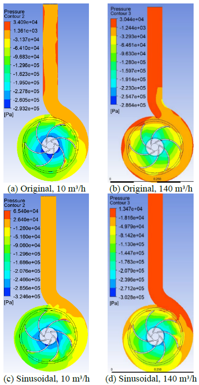
In order to examine the fluid behavior inside the pump when modifying the rotor trailing edges, the pressure contours shown in Figure 7 are generated for flow rates of 10 and 140 m³/h.
Figure 7. Pressure contours showing the effect of modifications on the trailing edge at the lowest (10 m³/h) and highest (140 m³/h) flow rates
For the lowest flow rate (10 m³/h), the sinusoidal and rectangular geometries increase the maximum fluid pressure and reduce the minimum pressure, which explains the higher hydraulic head (H) obtained. On the other hand, for the highest flow rate (140 m³/h), the pressure pattern changes; For the three modified geometries, the difference between maximum and minimum pressure decreases, suggesting a lower hydraulic head compared to the original geometry.
The sinusoidal and rectangular configurations, under the lowest flow conditions, exhibit a more balanced pressure distribution in the rotor discharge area. This results in increased pressure on the pressure side of the blade and, simultaneously, a reduction in low-pressure areas near the impeller inlet. This behavior indicates lower vortex intensity at the trailing edge, which in turn means less hydraulic energy dissipation. This leads to more efficient energy transfer to the fluid and an increase in hydraulic head. These findings are consistent with previous research, which indicates that geometric changes in the discharge zone help stabilize the pressure field and reduce losses caused by the interaction between stationary parts of the pump and vortex structures. Conversely, for the highest flow rate, the increased flow velocity alters the pressure pattern inside the pump. A decrease in the pressure gradient between the rotor outlet and the volute is observed in the modified geometries, demonstrating a reduced ability to convert mechanical energy into static pressure. This behavior can be explained by the increased interaction between the volute and the vane wake, as well as the intensification of flow separation and turbulent mixing. These phenomena increase hydraulic losses and decrease the pump's head compared to its original geometry. The mechanism mentioned above is consistent with studies that link the reduction of hydraulic performance in high flow circumstances with the increase in energy dissipation and the strengthening of the interaction between the rotor and the stator [18].
3.3 Velocity on the trailing edge of the impeller
For this analysis, Figures 8 and 9 show the flow velocity vectors at the impeller outlet for flow rates of 140 and 20 m³/h, respectively, for the original and trapezoidal trailing edge geometries. In Figure 8, the flow at the outlet of the impeller with the original blade geometry is uniform, with velocities between 10 and 16 m/s. Conversely, a turbulent zone, represented by velocities less than 5 m/s, is present near the outlet of the impeller with the trapezoidal blade geometry. This would cause a loss of flow energy and explain the lower head achieved by the pump with this blade geometry compared to the original one.

(a) Original

(b) Trapezoidal
Figure 8. Velocity vector at a flow rate of 140 m³/h
On the other hand, for a flow rate of 20 m³/h (Figure 9), the flow behavior for the original and trapezoidal geometries is inverted in relation to the flow rate of 140 m³/h. The blades with a trapezoidal trailing edge show a flow with velocities between 8 and 16 m/s at the exit of the impeller, these being greater than those of the original geometry. In the turbulent zone at the exit of the impeller with blades of original geometry, the speeds are less than 8 m/s. In the same way, the turbulence generated by the trailing edge of the original geometry would cause a loss of energy, making the head generated by the pump lower than that with a trapezoidal trailing edge.

(a) Original

(b) Trapezoidal
Figure 9. Velocity vector at a flow rate of 20 m³/h
3.4 Analysis of the characteristic curves
The flow rates studied in this research fall within the operating ranges described in the specialized literature. In the research of Xu et al. [11], for example, low flow rates, between 0 and 60 m³/h, were used to calculate the head (H) when analyzing the pump's characteristic curve. Similarly, the hydraulic behavior analysis shown in the study of Li et al. [23] used a flow rate range of 0 to 30 m³/h. On the other hand, to determine the head, Aliuly et al. [24] analyzed the hydraulic performance under high flow rate conditions, ranging from 200 to 400 m³/h. While some studies have simulated pumps with nominal flow rates, others have simulated pumps for low flow rates. Therefore, in this research, a wide flow rate range was chosen, from 10 m³/h to 140 m³/h, which is the maximum flow rate specified in the pump's technical data sheet.
The results of H as a function of flow rate, obtained from the simulations performed for the modified blades, are presented in Figure 10. It is observed that the original blade geometry yields higher H values than the modified geometries for flow rates above 60 m³/h. This behavior indicates that, in high-speed contexts, the consequences of the interaction between the rotor and the volute, as well as boundary layer separation and turbulent mixing, become more pronounced, leading to an increase in energy dissipation losses. Therefore, the hydraulic head achieved is limited because the impeller reduces the pressure gradient. It is important to note that, for a flow rate of 40 m³/h, the trapezoidal geometry was the only configuration that could surpass the original design by 2.17% in terms of height (H). However, at 60 m³/h, it decreases drastically compared to the others, showing a rather irregular behavior.

Figure 10. Effect of trailing-edge geometry on the hydraulic load curve (H–Q)
For flow rates lower than 20 m³/h, all three modified geometries exhibit higher H values compared to the original impeller configuration. This behavior could be linked to a reduction in local hydraulic losses in the rotor discharge zone, as well as a more uniform pressure distribution. The trailing edge can be modified to generate a more uniform flow, which reduces vortex strength and improves the use of the energy provided by the impeller.
These results demonstrate that the suggested modifications improve hydraulic performance, especially under low flow conditions. As the flow rate increases, the performance discrepancy between the geometries decreases, and the head values shown by the modified configurations are lower than those achieved with the original geometry.
When analyzing sinusoidal outlet geometries, an increase in H of 2.4% at nominal flow rates and 7.8% at high flow rates was reported [18]. On the other hand, in the present study, the maximum benefit of the sinusoidal configuration is observed for a low flow rate of 10 m³/h, which produces an H of 29.241 m, higher than the 27.623 m obtained with the original geometry, representing an increase of 5.86%.
The literature has studied the implementation of a sinusoidal trailing edge on the rotor blades, which reduces energy losses and pressure pulsations caused by rotor-stator interaction, while simultaneously increasing the pump's hydraulic performance [18]. Similarly, in the field of geometric optimization of centrifugal pumps, several studies have examined how impeller and volute parameters jointly affect hydraulic performance. In this context, a multi-objective optimization methodology was developed that employs CFD simulations, genetic algorithms, and response surface Kriging (MOGA), taking into account the impeller outlet width as a design variable [5]. In the field of trailing edge optimization for centrifugal pump impellers, several studies have explored the implementation of biomimetic geometries to regulate vortex shedding and increase flow stability. Unlike previous research [17-20] focused on sinusoidal tubercle trailing edges, the main contribution of the present work focuses on the analysis of three novel trailing edge geometries for centrifugal pump impellers, where rectangular and trapezoidal configurations had not been previously evaluated in this context. This makes it possible to determine their effect on head and contribute new criteria for improving the design of centrifugal pump impellers. The results of this study further corroborate that smooth geometric transitions at the trailing edge of the impeller blades help reduce internal hydraulic losses in centrifugal pumps.
In the present study, the effect of modifying the trailing-edge geometry of the rotor blades of the Grundfos NB 80-250/270 centrifugal pump on its hydraulic head H was investigated. CFD simulation was used to evaluate the hydraulic performance of three new geometries on the trailing edges of the rotor blades; the geometries correspond to a sinusoidal, rectangular, and trapezoidal shape.
The three proposed geometries showed a higher H value than the original at speeds of 10 m³/h and 20 m³/h, with the sinusoidal shape standing out at the lower speed. The sinusoidal and rectangular configurations showed lower H values compared to the original at higher speeds. However, the trapezoidal configuration exhibited more irregular behavior, surpassing the original geometry up to a speed of 40 m³/h, after which its H value dropped drastically with increasing speed. The analysis of pressure and velocity around the impeller's trailing edge demonstrates that the studied geometries influence energy dissipation losses through vortex shedding, positively and negatively at high and low speeds, respectively. These results show that it is feasible to optimize the trailing edge to improve the performance of centrifugal pumps within specific operating ranges, without requiring significant changes to the overall impeller geometry. From a design perspective, the results offer guidelines for new impellers that are better suited to diverse operating conditions, which can allow for more efficient and stable performance throughout their lifespan. The CFD-based methodology further confirms its reliability as a tool for investigating and optimizing trailing-edge geometric configurations to improve pump performance in industrial applications. Future research will include a parametric analysis of the amplitude and wavelength combinations of the sinusoidal, rectangular, and trapezoidal waveforms proposed in this study. The research will also be expanded to include other centrifugal pump models with different specific speeds and operating conditions. Finally, the experimental validation of these proposed configurations will be developed through tests on a test bench to evaluate the reliability of the numerical model.
The authors would like to acknowledge the project “Diseño de un biosensor plasmónico de tin para detección precisa de creatina mediante pit y resonancias fano” (code 23-2025-004102) from the Universidad Nacional de Ingeniería for supporting the use of the software that made this research possible. The authors also acknowledge the Universidad Tecnológica del Perú for providing the facilities that supported this research.
|
$g$ |
gravitational acceleration, m‧s⁻² |
|
H |
hydraulic head, m |
|
k |
turbulent kinetic energy, m²‧s⁻² |
|
$\tilde{G}_k$ |
generation of turbulent kinetic energy due to mean velocity gradients, kg m⁻¹‧s⁻³ |
|
$G_\omega$ |
generation of specific dissipation rate, kg‧m⁻³‧s⁻² |
|
$D_\omega$ |
cross-diffusion term, kg m⁻³‧s⁻² |
|
$p$ |
static pressure, Pa |
|
$S_k$ |
user-defined source term in the k-equation, kg‧m⁻¹‧s⁻³ |
|
$S_\omega$ |
user-defined source term in the ω-equation, kg‧m⁻³‧s⁻² |
|
t |
time, s |
|
$u_i$ |
velocity component in the i-direction, m‧s⁻¹ |
|
$V$ |
velocity vector, m‧s⁻¹ |
|
$x_i, x_j$ |
cartesian coordinates, m |
|
$Y_k$ |
dissipation term of turbulent kinetic energy, kg‧m⁻¹‧s⁻³ |
|
$Y_\omega$ |
dissipation term of the specific dissipation rate, kg‧m⁻³‧s⁻² |
|
Greek symbols |
|
|
$\Gamma_k$ |
effective diffusivity of turbulent kinetic energy, kg‧m⁻¹‧s⁻¹ |
|
$\Gamma_\omega$ |
effective diffusivity of the specific dissipation rate, kg‧m⁻¹‧s⁻¹ |
|
$\mu$ |
dynamic viscosity, kg‧m-1‧s-1 |
|
$\rho$ |
fluid density of water, kg‧m-3 |
|
$\omega$ |
specific dissipation rate, s⁻¹ |
|
Subscripts |
|
|
$d$ |
discharge (pump outlet) |
|
$i$ |
cartesian coordinate direction |
|
$j$ |
cartesian coordinate direction |
|
$k$ |
turbulent kinetic energy |
|
$s$ |
suction (pump inlet) |
|
$\omega$ |
specific dissipation rate |
[1] Song, Z., Chen, Y., Yu, T., et al. (2024). Influence of the trailing edge shape of impeller blades on centrifugal pumps with unsteady characteristics. Processes, 12(3): 508. https://doi.org/10.3390/pr12030508
[2] Wang, Y., Deng, X., Geng, M., Tao, R., Li, Y., Zhu, Z. (2024). Influence of blade wrap angle on internal flow and wear performance of solid-liquid two-phase centrifugal pump with semi-open impeller. Advances in Mechanical Engineering, 16(6): 16878132241258827. https://doi.org/10.1177/16878132241258827
[3] Riahinezhad, L., Nooraeen, A., Mohammadkhah, M., Hassani, K. (2026). Coupled computational fluid dynamics–Aeroacoustic analysis of fan noise: Influence of rotational speed, inflow, and blade serrations. Power Engineering and Engineering Thermophysics, 5(1): 1-17. https://doi.org/10.56578/peet050101
[4] Piancastelli, L. (2025). CFD-Based analysis and optimization of depressurization systems for engine test benches of small propeller aircraft. Power Engineering and Engineering Thermophysics, 4(2): 110-120. https://doi.org/10.56578/peet040203
[5] Wang, X., Wu, H., Xia, Y. (2026). Optimization and validation of a micro-centrifugal pump based on a CFD simulation and optimization platform. Applied Sciences, 16(10): 4599. https://doi.org/10.3390/app16104599
[6] Sakran, H.K., Abdul Aziz, M.S., Khor, C.Y. (2025). Blade exit angle impact on centrifugal pump performance: Entropy generation and fluid–structure interaction analysis. Arabian Journal for Science and Engineering, 50(4): 2509-2525. https://doi.org/10.1007/s13369-024-09200-5
[7] Sakran, H.K., Aziz, M.S.A., Khor, C.Y. (2024). Blade wrap angle impact on centrifugal pump performance: Entropy generation and fluid-structure interaction analysis. Computer Modeling in Engineering and Sciences, 140(1): 109-137. https://doi.org/10.32604/CMES.2024.047245
[8] Susilo, S.H., Setiawan, A. (2021). Analysis of the number and angle of the impeller blade to the performance of centrifugal pump. EUREKA: Physics and Engineering, (5): 62-68. https://doi.org/10.21303/2461-4262.2021.002001
[9] Peng, G., Chen, Q., Zhou, L., Pan, B., Zhu, Y. (2020). Effect of blade outlet angle on the flow field and preventing overload in a centrifugal pump. Micromachines, 11(9): 811. https://doi.org/10.3390/MI11090811
[10] Zhao, W., Liu, M., Liu, Y., Sheng, J., Song, Q. (2015). Effects of blade thickness on performance of low-specific-speed centrifugal pump. Journal of Drainage and Irrigation Machinery Engineering, 33(12): 1033-1037. https://doi.org/10.3969/j.issn.1674-8530.14.1005
[11] Xu, Z., Kong, F., Tang, L., Liu, M., Wang, J., Qiu, N. (2022). Effect of blade thickness on internal flow and performance of a plastic centrifugal pump. Machines, 10(1): 61. https://doi.org/10.3390/machines10010061
[12] Zhang, N., Gao, B., Wang, X., Liu, X., Ni, D. (2020). Effects of cutting the blade on the performance and pressure pulsation of a centrifugal pump. Energy Science & Engineering, 8(5): 1510-1523. https://doi.org/10.1002/ESE3.608
[13] Ding, H., Ge, F., Wang, K., Lin, F. (2023). Influence of blade trailing-edge filing on the transient characteristics of the centrifugal pump during startup. Processes, 11(8): 2420. https://doi.org/10.3390/pr11082420
[14] Huang, B., Zeng, G., Qian, B., Wu, P., Shi, P., Qian, D. (2021). Pressure fluctuation reduction of a centrifugal pump by blade trailing edge modification. Processes, 9(8): 1408. https://doi.org/10.3390/pr9081408
[15] Cui, B.L., Sun, F.Y., Zhang, Y.L., Liu, J.X., Xiao, J.J. (2023). Influence of blade trailing edge profile on unsteady pressure pulsations in a multistage centrifugal pump. Energy Science & Engineering, 11(4): 1471-1483. https://doi.org/10.1002/ESE3.1404
[16] Cui, B., Chen, Z., Zhang, Y. (2024). Influence of blade trailing edge profile on pressure pulsation in high-speed centrifugal pump. AIP Advances, 14(6). https://doi.org/10.1063/5.0211199
[17] Lin, Y., Li, X., Li, B., Jia, X., Zhu, Z. (2021). Influence of impeller sinusoidal tubercle trailing-edge on pressure pulsation in a centrifugal pump at nominal flow rate. Journal of Fluids Engineering, 143(9): 091205. https://doi.org/10.1115/1.4050640
[18] Lin, P., Wang, C., Song, P., Li, X. (2023). Analysis of the energy loss and performance characteristics in a centrifugal pump based on sinusoidal tubercle volute tongue. Entropy, 25(3): 545. https://doi.org/10.3390/e25030545
[19] Li, B., Li, X., Jia, X., Chen, F., Fang, H. (2019). The role of blade sinusoidal tubercle trailing edge in a centrifugal pump with low specific speed. Processes, 7(9): 625. https://doi.org/10.3390/pr7090625
[20] Lin, Y., Li, X., Zhu, Z., Wang, X., Lin, T., Cao, H. (2022). An energy consumption improvement method for centrifugal pump based on bionic optimization of blade trailing edge. Energy, 246: 123323. https://doi.org/10.1016/j.energy.2022.123323
[21] Grundfos. Technical Data Sheet: NB 80-250/270 Centrifugal Pump.
[22] Zanini, N., Suman, A., Piovan, M., Pinelli, M. (2025). Centrifugal pump performance derating with non-Newtonian slurries. Journal of the Global Power and Propulsion Society, 9: 47-57. https://doi.org/10.33737/jgpps/202255
[23] Li, J., Tang, L., Zhang, Y. (2020). The influence of blade angle on the performance of plastic centrifugal pump. Advances in Materials Science and Engineering, 2020(1): 7205717. https://doi.org/10.1155/2020/7205717
[24] Aliuly, A., Amanzholov, T., Seitov, A., Momysh, N., Jaichibekov, N., Kaltayev, A. (2024). Hydraulic design and CFD-based parametric study for optimizing centrifugal pump impeller performance. Applied Sciences, 14(22): 10161. https://doi.org/10.3390/APP142210161