Awfa Aladwani* | Mohammed Obaidi | Mahmood Alfathe | Zaid H. Alsawaff
© 2026 The authors. This article is published by IIETA and is licensed under the CC BY 4.0 license (http://creativecommons.org/licenses/by/4.0/).
OPEN ACCESS
We investigate an unmanned aerial vehicle (UAV)-assisted wireless communication network that employs intelligent reflecting surfaces (IRS) to enhance physical-layer security and reliability against eavesdropping. The proposed system integrates a cooperative decode-and-forward (DF) relay realized by a UAV with hybrid radio frequency/free-space optical (RF/FSO) links to improve outage performance while securing data transmission. An IRS (passive or active) is deployed on the UAV to reconfigure wireless propagation, creating virtual line-of-sight paths and directing signal energy toward legitimate users. We provide a simulation-based numerical analysis of the outage probability and secrecy performance of the proposed system under practical impairments including imperfect channel state information (CSI), IRS phase errors, and FSO pointing misalignment. Artificial noise (AN) and joint power/beamforming optimization are employed to enhance secrecy performance. Simulation-based results in the downlink show that aerial IRS with many elements significantly reduces secrecy outage, and active IRS can not only compensate for multiplicative path loss but also achieve substantial secrecy-capacity gains.
unmanned aerial vehicle, intelligent reflecting surfaces, hybrid radio frequency/free-space optical, decode-and-forward, artificial noise
Driven by the development of sixth-generation (6G) networks, the need for secure, energy-efficient, and high-throughput wireless communications has become more urgent. Two attractive candidates to realize such a vision are the unmanned aerial vehicles (UAVs) and intelligent reflecting surfaces (IRSs), which have become more widely acknowledged as enablers of this paradigm. UAVs provide flexible relaying with adaptive positioning on demand, whereas IRSs alter the propagation environment by way of passive reflection. Their combination has the potential to bring not only a significant performance enhancement on coverage and capacity but also to facilitate the enhancement of physical layer security (PLS), and hence UAV-IRS systems are seen as prospective pillars of future wireless architectures. In particular, the high-quality line-of-sight channels UAVs can provide are favorable not only to legitimate users but also to eavesdroppers, which can be resolved by reconfigurable intelligent surfaces through smartly modifying the wireless environment to boost secure transmission [1, 2].
However, practical implementation of IRS-aided systems is not without challenges, such as the “double fading” effect, which can be mitigated by active IRS and relaying protocols [3]. Active IRS introduces controllable power amplifiers into its reflecting elements to compensate for the path loss, enabling dynamic user scheduling according to channel quality, and the best achievable secrecy capacity can be obtained [4].
The latest studies reveal that UAVs carrying IRSs can enhance beneficial links and reduce information leakage to the eavesdroppers. For example, IRS-enabled UAVs in low-altitude platform and vehicular IoT paradigms mitigate secrecy outage probability in high mobility scenarios [5]. Cognitive UAV communications with IRS assistance are further investigated to achieve secure spectrum sharing, where an iterative optimization solution enhances secrecy capacity without violating the interference limitations [6]. Safe transmission protocols for IRS-UAV-enabled was investigated as well [7], and the design of a multi-functional RIS mounted on a UAV to defeat jamming and multipath fading has been studied, which enhances the security of wireless aerial networks [8].
The synergistic attributes of the radio frequency (RF) and free-space optical (FSO) systems have also been intensively investigated. Although FSO provides high-capacity line-of-sight communication, it is sensitive to atmospheric turbulence and pointing errors. RF links, even if much smaller in bandwidth, are known to be more resilient to blockage and turbulence. Hybrid IRS-assisted radio frequency/free-space optical (RF/FSO) systems are therefore a good candidate to exploit these trade-offs. Recent work illustrates that the secrecy outage probability and the achievable secrecy capacity in such systems significantly depend on turbulence parameters, complexity of IRS phase alignment, as well as UAVs' position, and, hence, these results demonstrate the importance of performing the joint performance analysis [9-11]. A structured comparison between the proposed system and the most relevant related works is summarized in Table 1.
Table 1. Comparison with related work
|
Reference |
IRS Type |
UAV Role |
Channel |
Relay |
CSI |
Method |
Optimized Variables |
AN |
Metrics |
Scope Limitation |
|
[1] |
Passive |
UAV receiver |
RF |
Direct |
Perfect |
Alternating optimization |
Uplink power, UAV trajectory, RIS phase |
No |
Average secrecy rate |
RF uplink; no DF or FSO |
|
[2] |
Active |
UAV carries active RIS; separate DF relays |
RF |
DF |
Statistical |
Analytical OP/IP |
Relay selection, RIS placement |
No |
Outage, intercept probability, SRT |
No FSO, AN, or joint beamforming |
|
[4] |
Active |
UAV transmitter; fixed active IRS |
RF |
Direct |
Perfect |
BCD + SCA/CCT/MM |
User scheduling, UAV trajectory, beamforming, active-IRS coefficients |
No |
Average secrecy capacity |
RF-only; fixed IRS; no DF or FSO |
|
[5] |
Passive |
Low-altitude platform |
RF |
Direct |
Perfect |
Convex optimization |
Power, phase shifts |
No |
Secrecy capacity |
DF hybrid RF/FSO relaying not considered |
|
[9] |
Passive |
No UAV |
RF |
DF relay + IRS |
Perfect |
Power-allocation analysis |
Power allocation |
No |
Security and reliability |
No FSO, active IRS, UAV, or imperfect CSI |
|
[10] |
Passive |
No UAV |
FSO→RF |
Dual-hop relay |
Perfect |
Analytical SOP |
NOMA power and RIS scenarios |
No |
Secrecy outage probability |
No active IRS, UAV, AN, or joint beamforming |
|
[12] |
Hybrid active/passive |
UAV-mounted hybrid IRS |
RF |
Direct |
Perfect |
SCA/FP/MM |
Beamforming; active/passive phase and amplitude |
No |
Achievable rate |
No DF, FSO, AN, or secrecy-outage analysis |
|
This work |
Active/passive |
UAV DF relay + IRS carrier |
RF→FSO |
DF |
Imperfect |
Phase alignment + space AN + grid search |
IRS phase/gain, beamforming, power split |
Yes |
Secrecy rate, outage, sensitivity |
Fixed geometry; normalized simulation model |
Energy-efficient design and energy harvesting for UAV-IRS systems have been reported in studies [12, 13]. Although AI/RL-based techniques (e.g., DRL for beamforming and phase-shift control in UAV-IRS networks [12]) have also been reported, they are outside the scope of the present work, which relies on optimization-based BCD-SCA rather than learning-based methods.
While most works are dedicated to passive IRSs, there exist a few results on active IRS architectures, where each reflecting element is equipped with a low-power amplifier. The multiplicative fading loss inherent in cascaded channels is compensated for by active IRSs, which also significantly enhance the secrecy rate and decrease the outage probability. UAV-borne active IRS relays have also been demonstrated to have better performance over their passive counterparts, especially under the circumstance of strong turbulence or weak line-of-sight links [4].
However, these are not yet been overcome. Various works consider perfect channel state information (CSI) and ideal IRS phase shift under the mobility of UAV and dynamic FSO turbulence. Combined characterization of outage probability and secrecy rate under UAV-IRS hybrid RF/FSO networks remains scarce. Analysis on the effect of practical impairments, including IRS phase quantization, UAV trajectory uncertainty, atmospheric turbulence, and hardware imperfections, on secure outage performance is deepened. Also, the integration of cooperative decode-and-forward (DF) relaying and artificial noise (AN) injection in a UAV-mounted IRS system has not been fully studied under imperfect CSI conditions.
Inspired by these challenges, we investigate in this paper a complete outage probability and secrecy analysis of UAV-aided hybrid RF/FSO systems with the assistance of the IRS technique. We introduce a cooperative DF scheme where the UAV-mounted IRS simultaneously enhances the legitimate link and weakens the eavesdropper's channel. The system explicitly considers turbulence-induced fading, pointing errors, Nakagami-m RF fading, and imperfect CSI. Extensive simulations illustrate that UAV-assisted IRS outperforms UAV-/IRS-assisted secure communication significantly, confirming its feasibility in 6G secure communication networks.
More directly related to this work, recent studies have focused on: (i) active IRS architectures with element-level amplification for compensating multiplicative path loss and enhancing secrecy [1, 2]; (ii) FSO pointing errors and Gamma-Gamma turbulence modeling in secure hybrid RF/FSO systems [9]; (iii) DF-based secure relaying with AN injection [5]; and (iv) secure IRS designs under imperfect CSI, where estimation errors reduce both beamforming quality and AN orthogonality [10]. The proposed manuscript integrates these directly relevant aspects into a single joint-optimization framework. The main contributions of this paper are as follows:
1. Novel System Architecture: We introduce active IRS, cooperative DF relaying, and hybrid RF/FSO links with artificial noise injection to the UAV-assisted secure communication system model for better physical-layer security.
2. Accurate Channel Modeling: A tight channel model is developed, which accounts for Nakagami-m RF fading, Gamma-Gamma ATM for FSO, pointing errors, practical impairments such as imperfect CSI, IRS phase quantization errors, and noise from amplifiers embedded in active IRS elements.
3. Joint Optimization Framework: A non-convex joint optimization problem based on IRS phase shifts (Θ), beamforming vectors (G), and power allocation factor (α) to maximize the average secrecy capacity is formulated and solved. A computationally efficient block coordinate descent (BCD) scheme combined with SCA and ternary search is proposed, while convergence is also analyzed.
4. Active vs. Passive IRS Analysis: reports a comparative study on passive and active IRS-based UAV-mounted hybrid RF/FSO secure communications, revealing that active IRS is capable of compensating for the multiplicative path loss and achieves up to 185% secrecy-capacity enhancement over baseline schemes under an equal-transmit-power comparison, and about 97% under a stricter equal-total-power comparison in which the amplifier supply power is fully accounted for; both scenarios are reported based on $10^4$ Monte Carlo realizations, guidelines for the deployment, the optimal UAV altitude (60 m), the optimal IRS array size (N = 128 elements), and the optimal power allocation (α* ≈ 0.59) are obtained, trading off secrecy capacity against computational complexity.
5. Performance characterization: We provide an analytical and numerical analysis of the secrecy outage probability under practical conditions, showing that the proposed system has Pout = $10^{-3}$ at 12 dB SNR (which corresponds to 10 dB gain as compared with the baseline system) with 4.82 bits/s/Hz of secrecy capacity.
The remainder of this paper is organized as follows. Section 2 presents the system model, problem formulation, and joint optimization algorithms. Section 3 provides simulation results and performance analysis. Section 4 concludes the paper with future research directions.
2.1 System and channel model
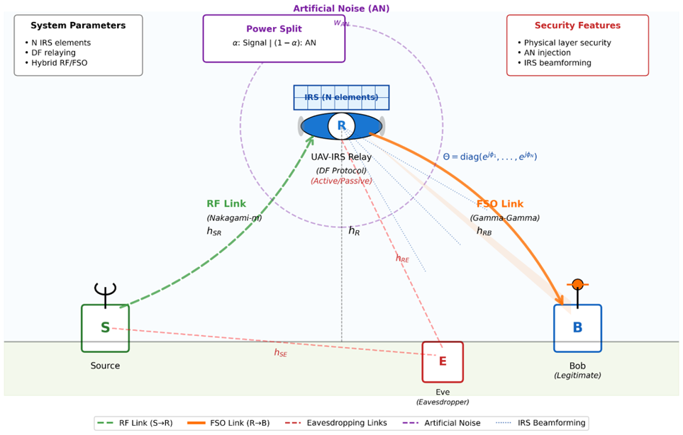
We consider a UAV-assisted secure communication network illustrated in Figure 1, where a ground source (S) transmits confidential information to a legitimate destination (Bob, B) via a UAV-mounted IRS relay (R), while an eavesdropper (Eve, E) attempts to intercept the transmission. The system employs a hybrid RF/FSO architecture operating in two distinct phases. In Phase 1, the S→R link operates over RF (Nakagami-m fading) to ensure reliable signal reception at the UAV relay under mobility conditions. In Phase 2, the R→B link operates over FSO (Gamma-Gamma atmospheric turbulence with pointing errors) to achieve high-capacity secure transmission to Bob. DF decoding takes place entirely at the UAV relay at the end of Phase 1: the UAV fully decodes the received signal before re-encoding and retransmitting in Phase 2. In the active IRS mode, each of the N reflecting elements phase-shifts and amplifies the impinging signal using an embedded low-noise amplifier, with element amplitude gain $\alpha_{\mathrm{n}}$, where in the passive IRS mode, each element only phase-shifts the signal, with unit amplitude gain $\alpha_{\mathrm{n}}$. Eve is assumed capable of intercepting transmissions in both phases, representing the worst-case eavesdropping scenario. In details, the UAV hovers at altitude $h_R$ and is equipped with an IRS comprising $N$ reconfigurable reflecting elements. The sourceto-relay link experiences Nakagami-$m$ with channel coefficient; $h_{S R}=\sqrt{\beta_{S R}} \cdot g_{S R}, g_{S R} \sim \operatorname{Nakagami}\left(m_{S R}, \Omega_{S R}\right)$ where $\beta_{\mathrm{SR}}=\rho_0\left(\mathrm{~d}_{\mathrm{SR}} / \mathrm{d}_0\right)^{-\alpha_{\mathrm{RF}}}$ represents large-scale path loss with reference distance $\mathrm{d}_0=1 \mathrm{~m}$, path loss exponent $\alpha_{\mathrm{RF}}=$ 2.5, and $\rho_0$ is the reference path gain. Then the instantaneous channel gain follows $\left|h_{S R}\right|^2 \sim \operatorname{Gamma}\left(m_{S R}, \frac{\Omega_{S R}}{m_{S R}}\right)$. The relay-to-destination FSO link is characterized by atmospheric turbulence modeled via Gamma-Gamma distribution and pointing errors. The channel coefficient is:
$h_{R B}^{\mathrm{FSO}}=h_a \cdot h_p \cdot h_l$ (1)
where, $\mathrm{h}_{\mathrm{a}} \sim \operatorname{Gamma}$-Gamma$(\alpha, \beta)$ is the atmospheric turbulence following a Gamma-Gamma distribution with shape parameters α and β (moderate turbulence, Rytov variance $\sigma^2{ }_R=0.5$), with PDF [14].
$f_{h_a}(x)=\frac{2(\alpha \beta)^{(\alpha+\beta) / 2}}{\Gamma(\alpha) \Gamma(\beta)} x^{(\alpha+\beta) / 2-1} K_{\alpha-\beta}(2 \sqrt{\alpha \beta x}), x>0$ (2)
The pointing error; $\mathrm{h}_{\mathrm{p}}=\mathrm{A}_0 \exp \left(-\frac{2 \mathrm{r}^2}{\mathrm{w}_{\mathrm{eq}}^2}\right)$, where r is radial displacement, $\mathrm{w}_{\mathrm{eq}}$ is equivalent beam radius, and $\mathrm{A}_0=$ $[\operatorname{erf}(\mathrm{v})]^2$ with $\mathrm{v}=\sqrt{\pi} \mathrm{a} /\left(\sqrt{2} \mathrm{w}_{\mathrm{eq}}\right)$. The pointing error coefficient follows $\left|\mathrm{h}_{\mathrm{p}}\right|^2 \sim \operatorname{Rayleigh}\left(\xi^2\right), \xi^2=\frac{\mathrm{w}_{\mathrm{eq}}^2}{4 \sigma_{\mathrm{s}}^2}$ where $\sigma_{\mathrm{s}}$ is the jitter standard deviation at the receiver. Besides, the path loss, $\mathrm{h}_1=\exp \left(-\sigma_{\mathrm{FSO}} \mathrm{d}_{\mathrm{RB}}\right)$ accounts for absorption/scattering over distance $d_{R B}$ (relay-to-Bob distance) with attenuation coefficient $\sigma_{\mathrm{FSO}}\left(\mathrm{dB} / \mathrm{km} ; \sigma_{\mathrm{FSO}}=0.43 \mathrm{~dB} / \mathrm{km}\right.$ for clear sky, 4.2 $\mathrm{dB} / \mathrm{km}$ for light fog, $20 \mathrm{~dB} / \mathrm{km}$ for moderate fog). Eavesdropper channels are modeled similarly as $\mathrm{h}_{\mathrm{SE}} \sim$ $\operatorname{Nakagami}\left(\mathrm{m}_{\mathrm{SE}}, \Omega_{\mathrm{SE}}\right), \mathrm{h}_{\mathrm{RE}}^{\text {FSO}} \sim \operatorname{Gamma-Gamma}\left(\alpha_{\mathrm{E}}, \beta_{\mathrm{E}}\right)$ with typically $\mathrm{m}_{\mathrm{SE}}<\mathrm{m}_{\mathrm{SR}}$ and $\alpha_{\mathrm{E}}<\alpha$, reflecting Eve's disadvantaged position.
The IRS phase shift matrix is defined as:
$\Theta=\operatorname{diag}\left(\theta_1, \theta_2, \ldots, \theta_N\right), \theta_n=\alpha_n e^{j \phi_n}$ (3)
where, $\alpha_{\mathrm{n}}$ as the element gain: passive IRS (unit gain, phaseshift only); $\alpha_n=1$; and active IRS: $\alpha_{\mathrm{n}}=\sqrt{\mathrm{G}_{\mathrm{n}}}$ (amplification gain, where $\mathrm{G}_{\mathrm{n}}$ is the element power gain; e.g., $\mathrm{G}_{\mathrm{n}}=4$ gives $\alpha_n=2$, equivalent to 6 dB$), \phi_{\mathrm{n}} \in[0,2 \pi]$.
Then, the cascaded channel from source to Bob through IRS is formulated as:
$h_{\text {eff}}^B=h_{R B}^T \Theta G h_{S R}$ (4)
where, $\mathrm{h}_{\mathrm{SR}} \in \mathrm{C}^{\mathrm{N} \times \mathbb{1}}$, is channel vector from S to IRS elements. $\mathrm{G}=\operatorname{diag}\left(\mathrm{g}_1, \ldots, \mathrm{~g}_{\mathrm{N}}\right)$ is the beamforming weight matrix at UAV, and $\mathrm{h}_{\mathrm{RB}} \in \mathrm{C}^{\mathrm{N} \times \mathbb{1}}$ is the channel vector from IRS elements to Bob.
Similarly, the effective eavesdropper channel is:
$h_{e f f}^E=h_{R E}^T \theta G h_{S E}$ (5)
To this end, the received signals at the UAV relay in the first phase (S→R) can be formulated as follows:
$y_R=\sqrt{P_S} h_{S R} x+n_R$ (6)
where, $x$ is the unit-power information symbol, $\mathrm{P}_{\mathrm{S}}$ is source transmit power ($P_S=P_T=1 \mathrm{~W}$ normalized), and $\mathrm{n}_{\mathrm{R}} \sim$ $\mathcal{C} \mathcal{N}\left(0, \sigma_{\mathrm{R}}^2\right)$ is the additive wight gaussian noise. Here $\sigma_{\mathrm{R}}^2, \sigma_{\mathrm{B}}^2$, and $\sigma_{\mathrm{E}}^2$ denote the noise powers at relay, Bob, and Eve respectively. In the second phase (R→B with artificial noise [15]), the relay employs DF with power splitting [16]. The transmitted signal is:
$s_R=\sqrt{\alpha P_R} G \hat{x}+\sqrt{(1-\alpha) P_R} w_{A N} z$ (7)
where, $\alpha \in(0,1)$ is the power allocation factor, $P_R$ is the relay transmit power, $\hat{x}$ is the decoded symbol, $w_{A N}$ is the artificial noise beamforming vector, $\left|w_{A N}\right|^2=1$, and $\mathrm{z} \sim \mathcal{C} \mathcal{N}(0,1)$ is the artificial noise.
To this end, Bob’s received signal can be obtained as:
$\begin{gathered}y_B=h_{e f f}^B s_R+n_B=\sqrt{\alpha P_R} h_{e f f}^B G \hat{x}+\sqrt{(1-\alpha) P_R} h_{e f f}^B w_{A N} z+n_B\end{gathered}$ (8)
Thus, the Bob SINR can be computed as:
$\gamma_B=\frac{\alpha P_R\left|h_{e f f}^B G\right|^2}{(1-\alpha) P_R\left|h_{e f f}^B w_{A N}\right|^2+\sigma_B^2}$ (9)
assuming $w_{A N}$ is designed to lie in the null-space of the estimated effective channel to $\operatorname{Bob}\left(h_{\text {eff }}^B \perp w_{A N}\right.$ under perfect CSI, so ideally $\left.h_{\text {eff }}^B \mathrm{w}_{\mathrm{AN}} \approx 0\right)$. The signal received at Eve can be calculated as follows:
$\begin{gathered}y_E=h_{e f f}^E s_R+n_E=\sqrt{\alpha P_R} h_{e f f}^E G \hat{x}+\sqrt{(1-\alpha) P_R} h_{e f f}^E w_{A N} z+n_E\end{gathered}$ (10)
Similarly, the Eve SINR can be calculated as:
$\gamma_E=\frac{\alpha P_R\left|h_{e f f}^E G\right|^2}{(1-\alpha) P_R\left|h_{e f f}^E w_{A N}\right|^2+\sigma_E^2}$ (11)
Finally, the instantaneous secrecy rate under DF is obtained by:
$R_S=\left[\min \left\{R_{S B}, R_{R B}\right\}-R_E\right]^{+}$ (12)
where, $\mathrm{R}_{\mathrm{SR}}=\log _2\left(1+\gamma_{\mathrm{SR}}\right)$, is $\mathrm{S} \rightarrow \mathrm{R}$ capacity with $\gamma_{\mathrm{SR}}=$ $\mathrm{P}_{\mathrm{S}}\left|\mathrm{h}_{\mathrm{SR}}\right|^2 / \sigma_{\mathrm{R}}^2$, the R→B capacity calculated by using $\mathrm{R}_{\mathrm{RB}}=$ $\log _2\left(1+\gamma_{\mathrm{B}}\right)$, and the eavesdropper rate over both phases (worst-case scenario where Eve intercepts both the S→E link in Phase 1 and the $\mathrm{R} \rightarrow \mathrm{E}$ link in Phase 2) is defined by the worst hop as: $R_E=\max \left\{R_E^1, R_E^2\right\}$, where $R_E^1=\log _2\left(1+\gamma_E^1\right)$ is Eve's rate in Phase 1 and $R_E^2=\log _2\left(1+\gamma_E^2\right)$ is Eve's rate in Phase 2; finally, $[x]^{+}=\max (0, x)$. Following DF relaying principles, the end-to-end achievable rate between S and Bob is limited by the weaker hop: $R_{S B}=\min \left\{R_{S R}, R_{R B}\right\}$. Therefore, the instantaneous secrecy rate $R_S$ in Eq. (12) explicitly incorporates the DF bottleneck and worst-case eavesdropping over both phases. On the other hand, the average secrecy capacity can be computed by using:
$C_s=E\left[R_s\right]$ (13)
And the secrecy outage probability for target rate obtained by [17]:
$P_{\text {out}}=\operatorname{Pr}\left(R_s<R_{t h}\right)$ (14)
Figure 1. UAV-IRS assisted secure hybrid radio frequency/free-space optical (RF/FSO) communication system model
2.2 Problem formulation
The goal is to maximize the average secrecy capacity of the two-hop UAV-IRS system while satisfying practical constraints. We formulate this as a joint optimization problem:
$\max _{\Theta, w, \alpha} C_s(\Theta, w, \alpha)=E\left[R_s\right]$ (15)
subject to:
$\alpha P_T+(1-\alpha) P_T \leq P_T$ (15a)
$\left|\varphi_n\right| \leq \varphi_m \alpha x, \forall n=1,2, \ldots, N$ (15b)
$0<\alpha<1$ (15c)
where, $w \in C^N$ is the beamforming weight vector at the UAV. The constraint Eq. (15a) ensures total power conservation at the relay (for passive IRS: $P_S+P_R=P_T$; for active IRS: $P_S+$ $P_R+N \cdot P_{a m p} \leq P_{b u d g e t}$, where $N \cdot P_{a m p}$ is the amplifier supply power consumption, thereby enforcing a fair power comparison with the passive baseline. The optimization variables are coupled through the secrecy rate expression:
$R_s=\left[\log _2\left(1+\gamma_B\right)-\log _2\left(1+\gamma_E\right)\right]^{+}$ (16)
where, $\gamma_B$ and $\gamma_E$ denote the SINR at the legitimate receiver Bob and Eavesdropper Eve, respectively.
2.3 Joint optimization via block coordinate descent
The formulated problem in Eqs. (15a)-(15c) is non-convex due to the coupled optimization variables in the cascaded channel model and the nonlinear SINR expressions. The coupling among different variables makes the direct solution of the original optimization problem challenging, as the variables cannot be optimized independently. We address this challenge using BCD combined with successive convex approximation (SCA), which has proven effective for similar IRS optimization problems [18, 19].
2.3.1 Block coordinate descent algorithm and convergence
BCD decomposes the joint optimization into three manageable subproblems, optimizing one variable while fixing the others. At each iteration $k$, we perform:
Step1:
$\Theta^{(k+1)}=\arg \max _{\Theta} C_s\left(\Theta, w^{(k)}, \alpha^{(k)}\right)$ (17)
Step2:
$w^{(k+1)}=\arg \max _w C_s\left(\Theta^{(k+1)}, w, \alpha^{(k)}\right)$ (18)
Step3:
$\alpha^{(k+1)}=\arg \max _\alpha C_s\left(\Theta^{(k+1)}, w^{(k+1)}, \alpha\right)$ (19)
This procedure repeats until convergence, defined by:
$\begin{aligned} \max \left(\mid \Theta^{(k+1)}-\right. & \Theta^{(k)}|,| w^{(k+1)}-w^{(k)}\left|,\left|\alpha^{(k+1)}-\alpha^{(k)}\right|\right)<\epsilon\end{aligned}$ (20)
where, $\epsilon=10^{-4}$ is the convergence tolerance. Under the standard BCD-SCA assumptions: (i) each per-block subproblem admits a well-defined solution up to a controlled tolerance, and (ii) the SCA surrogate is a tight lower bound of the objective at the current iterate with matching gradients, the objective sequence generated by the proposed algorithm is monotonically non-decreasing and bounded and therefore converges. Because the subproblems are solved iteratively rather than to global optimality, and because the joint problem is non-convex, this convergence is to a stationary point of the surrogate problem (in the KKT sense) rather than a global optimum, consistent with classical BCD-SCA analyses [20, 21]. Convergence to a stationary point of the original Lagrangian is therefore not claimed in the strict sense but is expected in practice; this is supported by the empirical monotonic convergence observed within a small number of iterations in our simulations.
2.3.2 Phase shift optimization via successive convex approximation
The IRS phase optimization subproblem is:
$\max _{\Theta} C_s(\Theta, w, \alpha)$ s.t. $\left|\theta_n\right| \in[0,2 \pi], \forall n$ (21)
This is non-convex due to the complex exponential coupling in the effective channel:
$h_{\mathrm{eff}}=h_{\mathrm{SI}}+h_{\mathrm{ID}} \odot(w \odot \Theta)$ (22)
where, $\odot$ denotes element-wise multiplication. We apply SCA by constructing a convex approximation of the secrecy capacity around the current solution $\Theta^{(k)}$. The effective channel gain can be expressed as:
$\left|h_{\mathrm{eff}}\right|^2=\left|h_{\mathrm{SI}}+h_{\mathrm{ID}} \odot(w \odot \Theta)\right|^2$ (23)
First-order Taylor expansion around $\Theta^{(k)}$ yields [22]:
$\left|h_{\mathrm{eff}}\right|^2 \approx\left|h_{\mathrm{eff}}^{(k)}\right|^2+2 \operatorname{Re}\left\{\left.\left(h_{\mathrm{eff}}^{(k)}\right)^* \nabla_\theta\left|h_{\mathrm{eff}}\right|^2\right|_{\theta^{(k)}}\right\}$ (24)
where the gradient is:
$\nabla_\theta\left|h_{\mathrm{eff}}\right|^2=\operatorname{conj}\left(h_{\mathrm{ID}} \odot w\right) \odot\left(h_{\mathrm{eff}}^{(k)}\right)^*$ (25)
The secrecy capacity is then approximated as:
$C_s \approx \log _2\left(1+\frac{\alpha P_T \mathrm{SNR} \cdot\left|h_{\mathrm{eff}}^{(k)}\right|^2}{1+\alpha P_T \mathrm{SNR} \cdot\left|h_{\mathrm{eff}}^{(k)}\right|^2}\right)-\log _2\left(1+\alpha P_T \mathrm{SNR} \cdot\left|h_{\mathrm{eve}}\right|^2\right)$ (26)
Projected gradient ascent update [23]:
$\Theta^{(k+1)}=\mathcal{P}\left(\Theta^{(k)}+\mu_{\Theta} \cdot \nabla_{\Theta} C_s\right)$ (27)
where, $\mu_{\Theta}=0.1$ is the step size and $\mathcal{P}(\cdot)$ projects the phases back to the unit circle:
$\mathcal{P}(z)=\frac{z}{|z|}$ (28)
To ensure monotonic improvement, we verify that $C_s\left(\Theta^{(k+1)}\right) \geq C_s\left(\Theta^{(k)}\right)$. If not, we reduce the step size by half and retry. This SCA procedure repeats for $I_{\text {SCA}}=5$ iterations per BCD iteration.
2.3.3 Beamforming vector optimization
The beamforming subproblem is:
$\max _w C_s(\Theta, w, \alpha)$ s.t. $|w|=1$ (29)
The effective channel at Bob is:
$h_{\text {eff, Bob}}=h_{\mathrm{SI}}+h_{\mathrm{ID}} \odot(\Theta \odot w)$ (30)
and the SINR becomes:
$h_{\text {eff, Bob}}=h_{\mathrm{SI}}+h_{\mathrm{ID}} \odot(\Theta \odot w)$ (31)
$\gamma_B=\alpha P_T \mathrm{SNR} \cdot\left|h_{\text {eff,Bob }}\right|^2=\alpha P_T \mathrm{SNR} \cdot\left|w^H\left(h_{\mathrm{ID}} \odot \Theta \odot h_{\mathrm{SI}}\right)\right|^2$ (32)
Gradient Computation:
$\nabla_w C_s=\frac{\partial C_s}{\partial \gamma_R} \cdot \nabla_w \gamma_B$ (33)
where,
$\nabla_w \gamma_B=2 \cdot \alpha P_T \mathrm{SNR} \cdot\left(h_{\mathrm{ID}} \odot \Theta\right) * \cdot\left(h_{\mathrm{SI}}\right)^T$ (34)
Gradient Ascent with Normalization:
$w^{(k+1)}=\frac{w^{(k)}+\mu_w \cdot \nabla_w C_s}{\left|w^{(k)}+\mu_w \cdot \nabla_w C_s\right|}$ (35)
where, $\mu_w=0.05$ is the beamforming step size. The normalization constraint $|w|=1$ is maintained at each update, which can be interpreted as normalizing the antenna gains. This optimization runs for $I_w=8$ iterations per BCD step.
2.3.4 Power allocation optimization via ternary search
The power allocation problem is:
$\max _{0 \leq \alpha \leq 1} C_s(\Theta, w, \alpha)$ (36)
Key observation: The secrecy capacity $C_s(\alpha)$ is a unimodal function in $\alpha$ it increases to a unique maximum and then decreases. This property arises from the competing effects of signal power and artificial noise power on the secrecy rate: for small $\alpha$, Bob's SINR is too low; for large $\alpha$, the AN power is insufficient to sufficiently degrade Eve's SINR. While strict analytical unimodality of $C_s(\alpha)$ is difficult to establish in closed form under active-IRS noise, DF relaying, and imperfect CSI, we have verified it numerically over an extensive range of conditions. Specifically, we swept $\alpha \in[0$, 1] in steps of 0.01 and computed $C_s(\alpha)$ at each of the operating points reported in the paper: $\mathrm{SNR} \in\{-10,0,10,20,30\} \mathrm{dB}$, CSI quality $\sigma^2{ }_{C S I} \in\{0,0.01,0.05,0.1\}$, IRS size $\mathrm{N} \in\{64$, 128, 256\}, and both passive and active IRS modes. In every tested scenario, $C_s(\alpha)$ exhibited a single global maximum with no observed local maxima. Under adverse conditions (e.g., $\sigma^2{ }_{C S I}=0.1$ combined with active IRS noise), the curve becomes flatter around the peak but remains unimodal. The unimodality assumption is therefore justified as an empirical property over the operating region of interest, and to exploit it, we employ ternary search, which converges to the global maximum in the unimodal regime in $O(\log (1 / \epsilon))$ function evaluations.
This method guarantees convergence to the global optimum with precision $10^{-6}$ in approximately $\log _3\left(10^6\right) \approx 13$ iterations per BCD step [24].
2.4 Handling practical impairments
In realistic deployments, perfect CSI, phase accuracy, and hardware performance cannot be guaranteed. We explicitly model these impairments.
2.4.1 Channel state information
The estimated channel is modeled as [25]:
$\hat{h}=h+\Delta h_{C S I}$ (37)
where, $\quad \Delta h_{\mathrm{CSI}} \sim \mathcal{C} \mathcal{N}\left(0, \sigma_{\mathrm{CSI}}^2|h|^2\right) \quad$ represents Gaussian estimation error such that $\hat{h}_{e f f}^B=h_{e f f}^B+\Delta h_{C S I}$. Because the AN vector $w_{A N}$ is designed in the null-space of the estimated channel $\hat{h}_{\text {eff}}^B$ rather than the true channel $h_{\text {eff}}^B$, a residual AN leakage appears at Bob under imperfect CSI: $\left|h_{\text {eff}}^B{ }^{\mathrm{H}} w_{A N}\right|^2=$ $\left|\Delta h_{C S I}{ }^{\mathrm{H}} w_{A N}\right|^2$, whose variance scales as $\sigma^2{ }_{\text {leak}}=\sigma^2{ }_{C S I}$. $\left|h_{\text {eff}}^B\right|^2 \cdot\left|w_{A N}\right|^2$. This leakage term is explicitly added to Bob's SINR denominator, so that Bob's effective SINR under imperfect CSI is reduced from its perfect-CSI value $\left(\gamma_B^{\text {perfect}}\right)$ to $\gamma_B^{\text {imp}}=\gamma_B^{\text {perfect}} /\left(1+\eta_{\text {leak}} \cdot \sigma^2{ }_C S I\right) \quad, \quad$ with $\eta_{\text {leak}}$ being the leakage sensitivity parameter. Consequently, a perfect null-space AN design is not assumed under imperfect CSI, and the residual leakage effect is quantified in all simulations reporting the imperfect-CSI results. In our simulations, we use three error levels:
Good CSI: $\sigma_{\mathrm{CSI}}^2=0.01$ (high-quality feedback)
Moderate CSI: $\sigma_{\mathrm{CSI}}^2=0.05$ (typical scenario)
Poor CSI: $\sigma_{\mathrm{CSI}}^2=0.1$ (low feedback capacity)
The optimization in Algorithm 1 uses $\hat{h}$ instead of perfect $h$, and we analyze performance degradation across all three scenarios.
|
Algorithm 1. Ternary Search for Optimal α |
. Compute $m_1=\alpha_{\text {left}}+\left(\alpha_{\text {right}}-\alpha_{\text {left}}\right) / 3$ . Compute $m_2=\alpha_{\text {right}}-\left(\alpha_{\text {right}}-\alpha_{\text {left}}\right) / 3$ . Evaluate $C_s\left(m_1\right)$ and $C_s\left(m_2\right)$ . If $C_s\left(m_1\right)<C_s\left(m_2\right):$ set $\alpha_{\text {left}}=m_1$ . Else: set $\alpha_{\text {right}}=m_2$
|
2.4.2 Intelligent reflecting surfaces phase quantization
Practical IRS elements cannot achieve arbitrary phase values due to hardware limitations. We model quantized phases as [26, 27].
$\theta_{\text {quantized}}=\operatorname{round}\left(\frac{\theta_{\text {optimal}}}{\Delta \phi}\right) \times \Delta \phi$ (38)
where, $\Delta \phi=2 \pi / M$ and $M$ is the number of quantization levels. We test $M \in 4,8,16$ bits per element and report performance vs. quantization resolution.
2.4.3 Active intelligent reflecting surfaces amplifier noise
For active IRS (amplification gain $\alpha_n=\sqrt{ } G_{a m p}=\alpha_n=2$), each reflecting element includes a low-noise amplifier with gain $G_{\mathrm{amp}}=2$ and noise figure $N F=4 \mathrm{~dB}$. The output of element $n$ is [28, 29].
$y_n=G_{\mathrm{amp}}\left(h_{\mathrm{in}, n} x+n_{\mathrm{amp}, n}\right)$ (39)
where, $n_{\text {amp}, n} \sim \mathcal{C} \mathcal{N}\left(0, \sigma_{\text {amp}}^2\right)$ with $\sigma_{\text {amp}}^2$ determined by the noise figure as $\sigma^2{ }_{a m p}=(F-1) \cdot k_B \cdot T \cdot B \cdot G_{a m p}$, where $F=10^{(N F / 10)}$ is the noise figure in linear scale, $k_B$ is Boltzmann's constant, $\mathrm{T}=290 \mathrm{~K}$ is the operating temperature, and B is the signal bandwidth. This amplifier noise degrades Eve's SINR less than Bob's SINR (due to beamforming steering), but the effect is explicitly included in results. To properly account for the power cost of active IRS elements, we now define the total active-IRS power consumption as $P_{I R S}=$ $N \cdot P_{\text {amp}}$, where $P_{\text {amp}}$ is the per-element amplifier supply power ($P_{\text {amp}} \leq P_{\text {max}}=10 \mathrm{~mW}$ per element in our study). The overall system power budget is therefore extended as $P_{\text {total}}=$ $P_S+P_R+N \cdot P_{\text {amp}} \leq P_{\text {budget}}$, so active IRS is not evaluated with free amplification. Moreover, the accumulated amplifier noise scales linearly with the number of active elements: the total noise power at the IRS output is $\sigma^2{ }_{\text {amp}}^{\text {total}}=N \cdot\left|\alpha_n\right|^2$. $\sigma^2{ }_{a m p}$, which is included in all SINR expressions and results for both Bob and Eve.
2.5 Simulation methodology
All results are validated via Monte Carlo simulation with $M=10,000$ channel realizations per SNR point. The simulation parameters are:
FSO Channel: Gamma-Gamma distribution with $\alpha_{\text {turb}}=2.9,~ \beta_{\text {turb}}=2.1$ (moderate turbulence) and pointing error variance $\sigma_s=0.1$.
RF Channels: Nakagami-m fading with shape parameters $m_{\mathrm{B}}=2.5$ (good link) and $m_{\mathrm{E}}=1.8$ (weaker link), reflecting the eavesdropper's disadvantageous position.
IRS Configuration: $N \in 64,128,256,512$ elements tested, with optimal value $N^*=128$ identified via complexity-performance trade-off analysis.
Active IRS Gain: $\alpha_n=2$ (6 dB amplification per element)
SNR Range: -10 to +30 dB.
Target Secrecy Rate: $R s_{t h}=2$ bits/s/Hz.
The complete set of simulation parameters used for reproducibility is summarized in Table 2.
Table 2. Complete simulation parameters for reproducibility
|
Parameter |
Symbol |
Value/Setting |
|
UAV altitude |
h |
60 m |
|
Horizontal distance: source to UAV projection |
$d_S$ |
30 m |
|
Horizontal distance: Bob to UAV projection |
$d_B$ |
40 m |
|
3D link distance: source-to-relay/UAV |
$d_{S R}$ |
67 m |
|
3D link distance: relay/UAV-to-Bob |
$d_{R B}$ |
200 m |
|
Source-to-Eve distance |
$d_{S E}$ |
100 m |
|
Optical wavelength |
λ |
1550 nm |
|
Receiver aperture diameter |
$D_r$ |
10 cm |
|
Beam divergence half-angle |
— |
1 mrad |
|
Equivalent beam radius |
$W_{e q}$ |
0.6 m |
|
Atmospheric attenuation coefficient |
$\sigma_{\text {FSO}}$ |
{0.43, 4.2, 20} dB/km (clear sky/light fog/moderate fog) |
|
Bandwidth |
B |
10 MHz |
|
Carrier frequency |
$f_c$ |
2.4 GHz |
|
Noise power |
$N_0$ |
−90 dBm |
|
Receiver/Bob/Eve noise variances |
$\begin{aligned} & \sigma^2{ }_R=\sigma^2{ }_B =\sigma^2{ }_E\end{aligned}$ |
$N_0$ |
|
Total power budget |
$P_{\text {budget}}$ |
30 dBm |
|
Source transmit power |
$P_S=P_T$ |
1 W (normalized) |
|
Active-IRS per-element supply power |
$\begin{aligned} & P_{a m p}\leq P_m a x\end{aligned}$ |
10 mW |
|
Noise figure |
NF |
4 dB |
|
Nakagami shape parameter for Bob |
$m_B$ |
2.5 |
|
Nakagami shape parameter for Eve |
$m_E$ |
1.8 |
|
Average channel power |
Ω |
1 |
|
Gamma-Gamma parameter |
$\alpha_{\text {turb}}$ |
2.9 |
|
Gamma-Gamma parameter |
$\beta_{\text {turb}}$ |
2.1 |
|
Jitter standard deviation |
$\sigma_s$ |
0.1 |
|
Number of IRS elements |
N |
{64, 128, 256, 512} |
|
Reference/nominal number of IRS elements |
N* |
128 |
|
Active IRS gain |
$\alpha_n$ |
2 (6 dB) |
|
Phase quantization resolution |
B |
{2, 3, 4, ∞} bits |
|
CSI error variance |
$\sigma_{C S I}^2$ |
{0, 0.01, 0.05, 0.1} |
|
Target secrecy rate |
$R s_{\text {th}}$ |
2 bits/s/Hz |
|
SNR range |
SNR |
−10 to +30 dB |
|
Channel realizations per SNR point |
— |
10⁴ |
Each simulation was run independently with different random seeds to ensure statistical independence across trials.
In this part, full simulation results are given to verify the performance of the proposed UAV-IRS secure communication system. All simulations are run via Monte Carlo with 10⁴ channel realizations to guarantee statistical reliability.
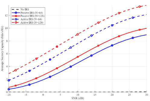
Figure 2. Average secrecy capacity versus SNR (comparison of secrecy capacity performance among different IRS configurations)
For different system modes, Figure 2 presents the average secrecy capacity performance over SNR. The results verify that the combination of IRS technology and UAV relaying outperforms traditional systems in terms of secrecy capacity enhancement. Passive IRS with N = 128 elements achieves, at SNR = 20 dB a value of 8.25 bits/s/Hz for the passive IRS, whereas the system without IRS can achieve only 1.69 bits/s/Hz. To ensure a fair active-versus-passive IRS comparison, results are now reported under two power-budget scenarios: (i) an equal-transmit-power (ETP) scenario, in which $P_S$ and $P_R$ are identical for both IRS configurations and the amplifier supply power $N \cdot P_{\text {amp}}$ is provided by a separate hardware budget; and (ii) an equal-total-power (EToP) scenario, in which the total power $P_{\text {total}}=P_S+P_R+N$. $P_{\text {amp}} \leq P_{\text {budget}}$ is fixed across both IRS configurations, so that any amplifier supply power consumed by the active IRS is deducted from the RF/FSO transmit budget. Under the ETP scenario, an active IRS with N = 128 elements achieves 12 bits/s/Hz at SNR = 20 dB, corresponding to a 185% gain over the no-IRS baseline. Under the more stringent EToP scenario, the same active IRS achieves approximately 8.4 bits/s/Hz, still corresponding to a substantial ~97% gain over the no-IRS baseline and a clear improvement over the passive IRS. The active IRS therefore still outperforms the passive IRS even when the amplifier supply power is fully accounted for. The active IRS design neutralizes the multiplicative path loss of cascaded channels via low-power amplification (gain $\alpha_n$ = 2), which is important to secure stable and secure links in actual applications.
The scalability results show performance improvement with increasing IRS elements from 64 to 128, implying an optimal tradeoff between performance and complexity for IRS element size. This saturation behavior is consistent with the theoretical result, where the array gain for passive IRS scales roughly as 10log₁₀(N) and is further amplified with an extra amplification term for the active setup.
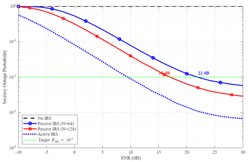
The secrecy outage probability for a given target secrecy rate $R s_{t h}$ = 2 bits/s/Hz, is provided in Figure 3. The DF two-hop protocol achieves a substantial reliability enhancement with the aid of the IRS. Without the IRS, an SNR of about 22 dB is necessary for the system to fulfill Pout = $10^{-2}$. The requirement is passive IRS (N = 64) 4 dB of gain for up to 22 dB, while passive IRS (N = 128) further provides a 7 dB gain for up to 17 dB. An active IRS with N = 128 elements can attain the target outage probability for as low as 10 dB, which yields a 10 dB gain over the baseline system. These results verify that not only does active IRS significantly improve the secrecy capacity, but it also substantially enhances the link reliability with realistic SNR constraints. The sharper declines of outage curves for IRS-assisted systems indicate that they achieve higher diversity gain, which is significant as it is challenging for UAVs to maintain stable channels in a dynamic environment due to the fading induced by mobility and atmospheric turbulence.
Figure 3. Average secrecy outage probability vs. SNR (outage probability analysis for target secrecy rate $R s_{t h}$ = 2 bits/s/Hz)
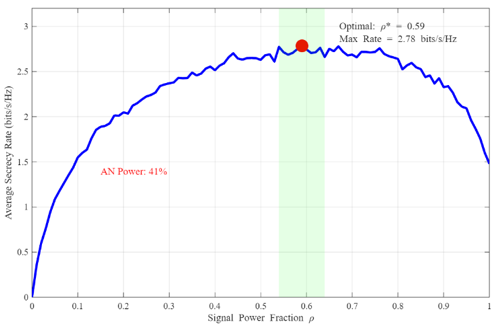
Figure 4. Artificial noise power optimization (impact of power allocation factor ρ on average secrecy rate)
Figure 4 illustrates the effect of the power control factor, ρ, on the average secrecy rate at SNR = 10 dB. The solution shows that the optimal signal power ratio is ρ* ≈ 0.59, which means about 41% of the total power is used for the generation of artificial noise. Accordingly, approximately 59% of the total power is allocated to the information signal and the remaining 41% to artificial noise.
The curve is clearly concave, and thus there is a single global optimum. The effect of too high a power allocation to AN (ρ < 0.5) significantly induces interference on the legitimate user, whereas insufficient power allocation to AN (ρ > 0.9) does not eliminate an eavesdropper sufficiently. Thus, the optimum power allocation changes with SNR; less AN power is needed for higher SNR values since the legitimate channel becomes dominant by itself. This power splitting is adjusted according to the active-passive mode switching strategy, together with IRS beamforming toward Bob and AN projection toward Eve, constitutes a complete PLS design approach.
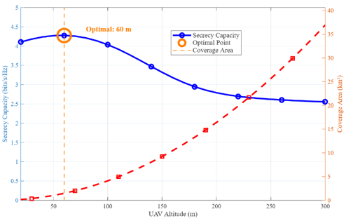
Figure 5. Unmanned aerial vehicle (UAV) altitude optimization (trade-off between secrecy capacity and coverage area vs UAV altitude)
Figure 5 describes the balance between secrecy capacity and coverage radius for the altitudes of UAV at 20-300 m. Before presenting this optimum, we specify the underlying height-dependent physical model. Let $h$ denote the UAV altitude and $d_{\mathrm{H}, \mathrm{SR}}, d_{\mathrm{H}, \mathrm{RB}}$, and $d_{\mathrm{H}, \mathrm{SE}}$ the horizontal distances from the UAV projection to $\mathrm{S}, \mathrm{Bob}$, and Eve, respectively ($d_{\mathrm{H}, \mathrm{SR}}=$ $30~ m, d_{\mathrm{H}, \mathrm{RB}}=40 ~m, d_{\mathrm{H}, \mathrm{SE}}=60 ~m$ in our study). The 3D link distances are $d_j(h)=\sqrt{h^2+d_{\mathrm{H}, \mathrm{j}}{ }^2}, j \in\{S R, R B, S E\}$. The RF path loss follows a height-dependent probabilistic LoS/NLoS model with LoS probability $P_{\text {LoS}}(h)=$ $\frac{1}{1+a \cdot \exp \left(-b \cdot\left(\theta_j(h)-a\right)\right)}$, where $\theta_j(h)=\arctan \left(\frac{h}{d_{\mathrm{H}_{\mathrm{j}}}}\right)$ is the elevation angle and $(a, b)$ are environment constants ($a=$ $9.61, b=0.16$ for suburban). The blockage probability $P_{\mathrm{NLoS}}(h)=1-P_{\mathrm{LoS}}(h)$ decreases as $h$ increases. The FSO pointing-error variance is altitude-dependent: $\sigma_p^2(h)=\sigma_\theta^2$. ($h^2+d_{\mathrm{H}, \mathrm{RB}}{ }^2$), where $\sigma_\theta=1 ~\mathrm{mrad}$ is the UAV attitude-jitter standard deviation, so higher altitude amplifies the beam misalignment at Bob. Ground users are assumed uniformly distributed within a disk of radius $d_{\mathrm{H}, \mathrm{RB}}$ centered at the UAV projection on the ground. Under this height-dependent pathloss and pointing-error model, the optimum altitude is found to be about $h^* \approx 60 \mathrm{~m}$, where the secrecy capacity is 4.35 bits/s/Hz. However, below this altitude, the performance is impaired by heavy path loss suffered by the ground terminal, although the condition is with good line-of-sight. At an altitude of 80 m, distance and elevation angle bring about FSO beam misalignment and R.F. signal attenuation over the distance.
The coverage area $A_{\text {cov}}(h)$ is defined precisely as the ground area on which the downlink SNR at Bob's ground plane exceeds a secrecy-rate threshold of $R_{s, t h}=2 \mathrm{bits} / \mathrm{s} / \mathrm{Hz}$, equivalently $\quad \gamma_B \geq \gamma_{t h}=2^{R_{s, t h}}-1=3$ (about 4.77 dB). Ground users are modeled as points uniformly distributed within a disk of radius $R_{\text {max}}=500 \mathrm{~m}$ around the UAV projection; for each candidate user location $r$ and altitude $h$, the effective SNR $\gamma_B(r, h)$ is computed under the heightdependent LoS/NLoS path-loss and pointing-error model above, and $A_{\text {cov}}(h)=\pi \cdot\left[\max \left\{r: \gamma_B(r, h) \geq \gamma_{\text {th}}\right\}\right]^2$ is the resulting coverage-disk area at altitude $h$. Under this definition, the area of coverage rises parabolically with the height, leading to $79.5 \mathrm{~km}^2$ at 200 m. However, this is at the expense of a lower secrecy capacity (a fall to a level of 2.8 bits/s/Hz). Security concerns that operators should consider when planning their mission as they balance security needs and coverage area requirements. High-security applications should operate UAVs at 50-100 meters, and surveillance/broadcast applications may accept even higher altitudes for distance coverage.
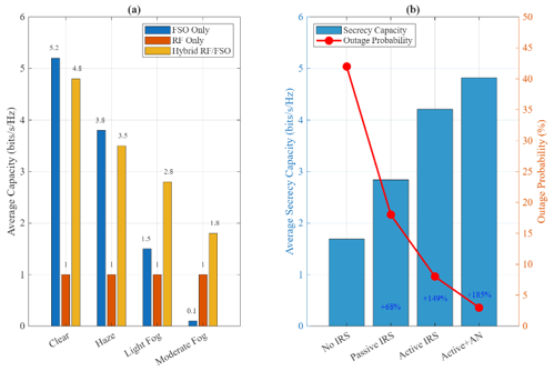
Figure 6. Hybrid radio frequency/free-space optical (RF/FSO) system performance: (a) Weather impact comparison (b) System configuration comparison
The weather scenarios in Figure 6 are analyzed under the same channel model used throughout the paper (Eq. (1), Eq. (2)): the FSO link follows Gamma-Gamma turbulence with shape parameters $(\alpha=2.9, \beta=2.1)$ and altitude-dependent pointing error $\sigma_p^2(h)$, while weather is captured through the Beer-Lambert atmospheric attenuation $\sigma_{F S O}(d B / k m)$. Three weather regimes are considered, each with its own value of $\sigma_{\text {FSO}}$: clear sky $\left(\sigma_{\text {FSO}}=0.43 \mathrm{~dB} / \mathrm{km}\right)$, light fog $\left(\sigma_{\text {FSO}}=\right.$ 4.2 dB/km) and moderate fog $\left(\sigma_{\text {FSO}}=\right.$ 20 dB/km). The Gamma-Gamma parameters $(\alpha, \beta)$ remain unchanged with fog because scintillation is dominated by clear-air turbulence rather than by particle scattering. The RF link is modeled by Nakagami- $m$ fading and is essentially weather-independent. The DF relay at the UAV performs per-hop link selection according to the rule "choose FSO if $C_{\text {FSO}}\left(h_l, \sigma_{\text {FSO}}, \sigma_p\right) \geq$ $C_{R F}$, else use RF , where $C_{F S o}$ and $C_{R F}$ are the instantaneous FSO/RF capacities computed under the same channel model. This dynamic switching is applied independently on the S→R and R→B hops, exploiting DF’s ability to fully decode and re-encode between phases; it is what enables the hybrid RF/FSO system to remain operational in fog. Resilience of system performance in a bad environment over different weather types is illustrated in Figure 6(a). Under clear sky, the FSO-only links achieve 5.2 bits/s/Hz but degrade drastically to 0.1 bits/s/Hz under the influence of moderate fog due to the scattering and absorption. RF-only links guarantee a weather-independent performance (1.0 bits/s/Hz), but unlike the other links, they are very robust with respect to the weather conditions. The proposed hybrid RF/ FSO system takes advantage of the two technologies’ complementary characteristics. When the FSO capacity falls to 0.1 bits/s/Hz in moderate fog, the hybrid system is able to achieve 1.8 bits/s/Hz by dynamically assigning more weight to the more dependable RF link. This dynamic link selection, made possible by the UAV’s capability to sense the atmospheric conditions, guarantees that security will be always maintained. The DF relaying protocol at the UAV is used to smartly switch between FSO and RF according to the instantaneous channel quality, thereby achieving path diversity against weather fading. Figure 6(b) contrasts the generalized system setups at SNR = 20 dB. The trends are consistent: passive IRS yields 68% capacity gain over no IRS, active IRS results in 149% improvement, and the integrated design with active IRS plus optimal AN achieves 185% enhancement. This happens while the secrecy outage probability reduces from 42% (without IRS) to just 3% (active IRS + AN), indicating that enhanced secrecy capacity leads to higher reliability.
This extensive investigation reveals that IRS with UAV relaying and hybrid RF/FSO architectures can offer great performance gains in secure wireless communications. The combined optimization of phases, beamforming, and power allocation leads to synergistic gains (total 185% improvement) larger than the sum of the individual component-wise gains. The qualitative statements below are backed by the following compact sensitivity summary, reported at:
The 60-meter optimal altitude and N = 128 element recommendation are two practical guidelines for the deployment. The 4.82 bits/s/Hz secrecy capacity at 20 dB SNR demonstrated by this design deems it as a viable candidate for 6G secure communication networks, thereby pushing the state-of-the-art in physical-layer security beyond the existing passive-IRS or beamforming-only approaches.
|
UAV |
Unmanned aerial vehicle |
|
IRS |
Intelligent reflecting surfaces |
|
DF |
Decode-and-Forward |
|
RF/FSO |
Radio frequency/Free-space optical |
|
CSI |
Channel state information |
|
AN |
Artificial noise |
|
6G |
Sixth generation |
|
PLS |
Physical layer security |
|
RL |
Reinforcement learning |
|
DRL |
Deep reinforcement learning |
|
SINR |
Signal to interference plus noise ratio |
|
BCD |
Block coordinate descent |
|
SCA |
Successive convex approximation |
|
NF |
Noise figure |
|
Greek symbols |
|
|
Θ |
Passive IRS phase matrix |
|
w |
Beamforming weight vector |
|
α |
Atmospheric turbulence parameter |
|
γB |
SINR at the legitimate receiver |
|
γE |
SINR at the Eavesdropper |
|
ϵ |
Convergence tolerance |
|
µΘ |
Step size |
|
σ |
Error variance |
|
β |
Atmospheric turbulence parameter |
|
Subscripts |
|
|
Cs |
Average secrecy capacity |
|
Rs |
Secrecy rate |
|
N |
Number of IRS elements |
|
K |
Iteration |
|
heff |
Cascaded channel from source to destination |
|
hSI |
Source-to-IRS channel |
|
hID |
IRS-to-destination channel |
|
hSE |
Eavesdropper channel |
|
hSR |
Source-to-relay channel |
|
hRB |
Relay-to-destination channel |
|
PT |
Total transmit power |
|
m |
Nakagami parameter |
|
Gamp |
low-noise amplifier gain of reflecting element |
|
M |
Number of quantization levels |
[1] Shang, Y.X., Peng, Y.Y., Ye, R.L., Lee, J. (2024). RIS-assisted secure UAV communication scheme against active jamming and passive eavesdropping. IEEE Transactions on Intelligent Transportation Systems, 25(11): 16953-16963. https://doi.org/10.1109/TITS.2024.3417932
[2] Yuan, J., Chen, G.J., Wen, M.W., Wan, D.H., Cumanan, K. (2024). Security-reliability tradeoff in UAV-carried active RIS-assisted cooperative networks. IEEE Communications Letters, 28(2): 437-441. https://doi.org/10.1109/LCOMM.2023.3347294
[3] Verma, G.D., Mathur, A., Ai, Y., Cheffena, M. (2022). Mixed dual-hop IRS-assisted FSO-RF communication system with H-ARQ protocols. IEEE Communications Letters, 26(2): 384-388. https://doi.org/10.1109/LCOMM.2021.3129594
[4] Miao, J.S., Li, T.J., Bai, S.L., Yan, S., Zhao, Y. (2023). Secrecy capacity enhancement in active IRS-assisted UAV communication system. Sensors, 23(9): 4377. https://doi.org/10.3390/s23094377
[5] Min, L.T., Li, J.W., He, Y.X., Si, Q. (2023). LAP and IRS enhanced secure transmissions for 6G-oriented vehicular IoT services. Drones, 7(7): 414. https://doi.org/10.3390/drones7070414
[6] Li, A., Guo, T., Wu, Q.Q., Wang, Z.W., Yan, L.Y., Hong, S. (2023). Secure IRS-aided cognitive UAV communications. In 2023 IEEE 23rd International Conference on Communication Technology (ICCT), Wuxi, China, pp. 1468-1473. https://doi.org/10.1109/ICCT59356.2023.10419706
[7] Wang, Z., Li, Z.Y., Wen, J.J., Zhao, M., Zhou, X.Y., Yu, L.S. (2023). Secure communication scheme for IRS-UAV enabled cognitive network. In 2023 3rd International Conference on Intelligent Communications and Computing (ICC), Nanchang, China, pp. 37-41. https://doi.org/10.1109/ICC59986.2023.10421671
[8] Wang, W., Ni, W.L., Tian, H., Eldar, Y.C., Niyato, D. (2023). UAV-mounted multi-functional RIS for combating eavesdropping in wireless networks. IEEE Wireless Communications Letters, 12(10): 1667-1671. https://doi.org/10.1109/LWC.2023.3283981
[9] Shi, Y., Zhao, D., Wu, Y. (2025). Hybrid intelligent reflective surfaces and relay assisted secure transmission scheme with power allocation. ETRI Journal, 47(1): 158-166. https://doi.org/10.4218/etrij.2023-0401
[10] Liu, X., Zhang, J.L., Luo, W.W., Song, J.Z., Xie, Y.Y., Pan, G.F. (2024). Secrecy outage analysis for RIS-assisted hybrid FSO-RF systems with NOMA. Digital Signal Processing, 151: 104561. https://doi.org/10.1016/j.dsp.2024.104561
[11] Zhang, Y.K., Zhou, J.S., Qu, G.X., Duan, X.T., Qu, K.G., Zhao, D.Z. (2023). Secure UAV computation offloading with intelligent reflecting surface. In 2023 IEEE International Conference on Unmanned Systems (ICUS), Hefei, China, pp. 199-204. https://doi.org/10.1109/ICUS58632.2023.10318417
[12] Dong, R.G., He, H.J., Shu, F., et al. (2023). Joint beamforming and phase shift design for hybrid IRS and UAV-aided directional modulation networks. Drones, 7(6): 364. https://doi.org/10.3390/drones7060364
[13] Kumar, S., Rai, J.K., Ranjan, P., Chowdhury, R. (2024). Secured and energy efficient wireless system using reconfigurable intelligent surface and PSO algorithm. In 2024 IEEE International Conference on Interdisciplinary Approaches in Technology and Management for Social Innovation (IATMSI), Gwalior, India, pp. 1-5. https://doi.org/10.1109/IATMSI60426.2024.10502696
[14] Al-Habash, M.A., Andrews, L.C., Phillips, R.L. (2001). Mathematical model for the irradiance probability density function of a laser beam propagating through turbulent media. Optical Engineering, 40(8): 1554-1562. https://doi.org/10.1117/1.1386641
[15] Goel, S., Negi, R. (2008). Guaranteeing secrecy using artificial noise. IEEE Transactions on Wireless Communications, 7(6): 2180-2189. https://doi.org/10.1109/TWC.2008.060848
[16] Laneman, J.N., Tse, D.N.C., Wornell, G.W. (2004). Cooperative diversity in wireless networks: Efficient protocols and outage behavior. IEEE Transactions on Information Theory, 50(12): 3062-3080. https://doi.org/10.1109/TIT.2004.838089
[17] Gopala, P.K., Lai, L., El Gamal, H. (2008). On the secrecy capacity of fading channels. IEEE Transactions on Information Theory, 54(10): 4687-4698. https://doi.org/10.1109/TIT.2008.928990
[18] Wu, Q.Q., Zhang, R. (2019). Intelligent reflecting surface enhanced wireless network via joint active and passive beamforming. IEEE Transactions on Wireless Communications, 18(11): 5394-5409. https://doi.org/10.1109/TWC.2019.2936025
[19] Guo, H.Y., Liang, Y.C., Chen, J., Larsson, E.G. (2020). Weighted sum-rate maximization for reconfigurable intelligent surface aided wireless networks. IEEE Transactions on Wireless Communications, 19(5): 3064-3076. https://doi.org/10.1109/TWC.2020.2970061
[20] Boyd, S., Vandenberghe, L. (2004). Convex Optimization. Cambridge University Press. https://web.stanford.edu/~boyd/cvxbook/bv_cvxbook.pdf.
[21] Nesterov, Y. (2018). Lectures on Convex Optimization, Second Edition. Springer Cham. https://doi.org/10.1007/978-3-319-91578-4
[22] Razaviyayn, M., Hong, M.Y., Luo, Z.Q. (2013). A unified convergence analysis of block successive minimization methods for nonsmooth optimization. SIAM Journal on Optimization, 23(2): 1126-1153. https://doi.org/10.1137/120891009
[23] Beck, A., Teboulle, M. (2009). A fast iterative shrinkage-thresholding algorithm for linear inverse problems. SIAM Journal on Imaging Sciences, 2(1): 183-202. https://doi.org/10.1137/080716542
[24] Cormen, T.H., Leiserson, C.E., Rivest, R.L., Stein, C. (2009). Introduction to Algorithms. Cambridge, MA, USA: MIT Press. https://www.amazon.com/Introduction-Algorithms-3rd-MIT-Press/dp/0262033844.
[25] Aladwani, A., Erdogan, E., Gucluoglu, T. (2019). Impact of co-channel interference on two-way relaying networks with maximal ratio transmission. Electronics, 8(4): 392. https://doi.org/10.3390/electronics8040392
[26] Di, B., Zhang, H.L., Song, L.Y., Li, Y.H., Han, Z., Poor, H.V. (2020). Hybrid beamforming for reconfigurable intelligent surface based multi-user communications: Achievable rates with limited discrete phase shifts. IEEE Journal on Selected Areas in Communications, 38(8): 1809-1822. https://doi.org/10.1109/JSAC.2020.3000813
[27] Wu, Q.Q., Zhang, R. (2020). Beamforming optimization for wireless network aided by intelligent reflecting surface with discrete phase shifts. IEEE Transactions on Communications, 68(3): 1838-1851. https://doi.org/10.1109/TCOMM.2019.2958916
[28] Long, R.Z., Liang, Y.C., Pei, Y.Y., Larsson, E.G. (2021). Active reconfigurable intelligent surface-aided wireless communications. IEEE Transactions on Wireless Communications, 20(8): 4962-4975. https://doi.org/10.1109/TWC.2021.3064024
[29] Zhang, Z.J., Dai, L.L., Chen, X.B., Liu, C.H., Yang, F., Schober, R. (2023). Active RIS vs. passive RIS: Which will prevail in 6G? IEEE Transactions on Communications, 71(3): 1707-1725. https://doi.org/10.1109/TCOMM.2022.3231893