Abbas Nasser Hasein* | Haibat Lafta
© 2026 The authors. This article is published by IIETA and is licensed under the CC BY 4.0 license (http://creativecommons.org/licenses/by/4.0/).
OPEN ACCESS
In piping systems, typically in oil and gas applications, welding between similar and dissimilar steel is often required. In this study, 5 mm thick API 5L carbon steel (CS) and AISI 316L stainless steel (SS) pipes were joined using Tungsten Inert Gas (TIG) welding with ER309L filler metal. Three joint configurations were prepared: carbon steel–carbon steel (CS–CS), stainless steel–stainless steel (SS–SS), and dissimilar carbon steel–stainless steel (CS–SS). Microstructural examination was carried out for all welded joints, while tensile testing was performed only for the SS–SS and CS–SS configurations to evaluate the influence of material mismatch on mechanical performance. The CS–CS joint was intentionally excluded from tensile testing and was used as a baseline reference for microstructural comparison. The differences in material properties and the microstructural gradients along the weld line were found to be responsible for the reduction in elongation in the CS–SS joint compared to the SS–SS joint, which had the greatest tensile strength and elongation. The results indicate the correlation between the weld's structure and the mechanical behavior of similar and dissimilar pipe joints.
Tungsten Inert Gas welding, dissimilar metals, carbon steel, stainless steel, AISI 316L, API 5L, ER309L, microstructure
Because of the Arc stability, controlled heat input and ability to produce clean and high-quality welds, Tungsten Inert Gas (TIG) welding is one of the most widely incorporated techniques in pipe fabrication. Dissimilar metal welding (DMW) between API 5L carbon steel (CS) and AISI 316L stainless steel (SS) is often demanded in corrosive environments in oil and gas pipelines. These transition joints must have mechanical integrity to provide reliable service in demanding operating conditions.
Since there are thermal expansion differences, carbon migration and microstructural changes at the fusion boundary, the dissimilar welding of CSs to SSs has been extensively investigated. Particularly, Oktadinata and Putra [1] have reported important hardness variation in the heat-affected zone (HAZ) of the SS–CS joints, especially on the CS side. Sabzi et al. [2] found that the most frequently occurring failure mode of dissimilar gas tungsten arc welding (GTAW) joints is due to mechanical incompatibility on the CS side of the joint. Rogalski et al. [3] also showed that the fusion boundary is a key factor in the localization of strain and initiation of fracture. Huang et al. [4] investigated S355JR/316L dissimilar joints produced by GTAW and reported significant microstructural and mechanical differences across the joint.
Another critical consideration is the choice of filler metal and its impact on the weld structure and properties. Khan et al. [5] confirmed that ER309L filler promotes formation of an austenitic weld structure with improved crack resistance, and Soleimani and Mostafaei [6] demonstrated the effect of filler composition on delta ferrite distribution and hardness development. Tayeb et al. [7] correlated the microstructural refinement of dissimilar SS joints with their mechanical performance, and found the strength of such dissimilar joints to be controlled by the weakest HAZ rather than the weld metal (WM). ER309L has also been used successfully for TIG joining of 316L stainless steel and P355GH carbon steel, with microstructural and mechanical characterization of the resulting joint [8].
The structural performance of welded joints has been the subject of several studies as well. Mechanical heterogeneity among base metal (BM), HAZ, and WM regions of pipeline girth welds was the focus of Zhang et al. [9] in studying fracture performance. Similarly, Krishnan et al. [10] studied fracture resistance on dissimilar steel welds and showed the effect of strength mismatch and stress concentration. Recent GTAW studies on 316L and mild steel have likewise linked the weld microstructure with tensile performance and fracture location [11]. However, the investigations were mostly done on a plate specimen or fracture mechanics sample and not a thin-walled pipe joint.
Besides the experimental studies, the optimization of welding processes, inspection techniques, numerical simulations and computational approaches have also helped in a better understanding of the performance of welded joints. Touileb et al. [11, 12], as well as Sharma and Dwivedi [13], found that the welding parameters have a significant influence on the penetration, microstructure, and mechanical performance of TIG and A-TIG welds. Aulia et al. [14] did a comparison of the tensile properties of steel pipes welded by shielded metal arc welding (SMAW) and metal inert gas (MIG) processes in pipe applications.
Moreover, Hasein et al. [15] proved that numerical modeling is beneficial in studying the mechanical behavior, fatigue performance, and heat transfer of welded joints. Data-driven and computational approaches have also demonstrated their ability to analyze stress distribution, deformation behavior, and the mechanical performance of engineering joints under various loading conditions, which is complementary to the present study. While these investigations are conducted with different materials, joints, and engineering applications, they all show the general use of experimental, numerical, and computational tools for assessing the structural integrity and mechanical performance of engineering joints.
Previous works have been carried out on fracture behavior and mechanical performance of similar and dissimilar steel welded joints. However, systematic comparison of thin-wall pipe welded joints made by similar (CS–CS and SS–SS) and dissimilar (CS–SS) welds under the same conventional TIG welding conditions is limited. Furthermore, the combined influence of the ferrite–pearlite CS microstructure, the fully austenitic SS microstructure, and the ER309L WM on tensile behavior has not been extensively clarified for practical pipe applications.
Therefore, this study aims to experimentally evaluate the microstructural features and tensile behavior of TIG-welded API 5L CS and AISI 316L SS pipe joints using ER309L filler metal. By comparing homogeneous and dissimilar configurations under practical conditions, this work seeks to improve the understanding of the relationship between microstructure and tensile behavior in pipeline transition joints.
In the present work, the CS–CS joint was included primarily as a reference for microstructural comparison, while mechanical evaluation focused on the SS–SS and CS–SS joints to investigate the influence of material mismatch.
2.1 Materials
In this work, the base materials used were:
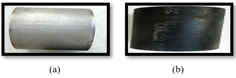
•API 5L carbon steel pipes (5 mm thickness) as in Figure 1(a).
•AISI 316L stainless steel pipes (5 mm thickness) as in Figure 1(b).
Figure 1. Base materials: (a) API 5L carbon steel (CS) pipe and (b) AISI 316L stainless steel (SS) pipe
The chemical composition of base materials and the main mechanical properties of base materials are mentioned in Tables 1 and 2.
Table 1. Nominal chemical composition of the base materials according to the relevant material specifications
|
Material |
C |
Mn |
Si |
P (max) |
S (max) |
Cr |
Ni |
Mo |
|
API 5L CS |
≤0.26 |
≤1.20 |
≤0.40 |
≤0.030 |
≤0.030 |
— |
— |
— |
|
AISI 316L SS |
≤0.03 |
≤2.00 |
≤1.00 |
≤0.045 |
≤0.030 |
16.0–18.0 |
10.0–14.0 |
2.0–3.0 |
Note: The symbol “≤” indicates the maximum permissible content specified by the applicable material standard, whereas “—” indicates that no specific value is specified for the corresponding element in the applicable standard. The chemical compositions presented in this table correspond to the nominal specification limits provided by the applicable material standards, as mill test certificates for the supplied materials were not available.
Table 2. Main mechanical properties of base materials
|
Material |
Yield Strength (YS), MPa |
Ultimate Tensile Strength (UTS), MPa |
Elongation, % |
|
API 5L |
≥245 |
≥415 |
≥22 |
|
AISI 316L (Annealed) |
≥170 |
≥485 |
≥40 |
Note: The mechanical properties presented in Table 2 correspond to the base materials in their as-received condition and are not measured properties of the welded joints. The tensile properties obtained from the welded joint specimens are reported separately in Table 5.
2.2 Specimen preparation
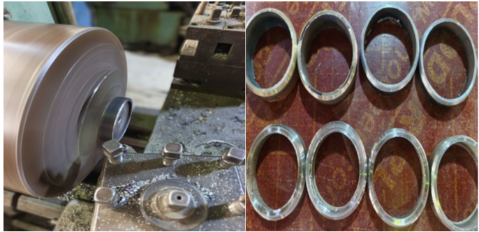
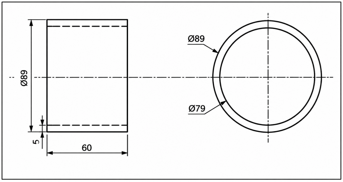
The pipes were prepared using a mechanical cutting saw and a lathe machine to obtain precise and consistent dimensions for all specimens, as shown in Figures 2 and 3, and then properly aligned prior to welding.
Figure 2. Specimen preparation
2.3 Joint configuration
Three joint configurations were prepared for this study, as shown in Figure 4:
·Stainless steel–stainless steel (SS–SS).
·Carbon steel–stainless steel (CS–SS).
·Carbon steel– carbon steel (CS–CS).
Figure 3. The specimen dimensions (all dimensions in mm)
Figure 4. Representation of welded pipe configurations
2.4 Welding procedure
TIG welding was used to make the joints and the welding parameters are mentioned in Table 3.
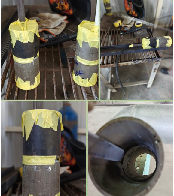
Shielding gas was supplied to prevent oxidation during both homogeneous and dissimilar welding operations, ensuring acceptable weld quality and minimizing surface oxidation of the specimens.
Filler metal (ER309L) was used during welding in the root pass, the filling stage, and the capping stage. The gas shielding and filler application procedure are illustrated in Figure 5.
Table 3. Tungsten Inert Gas (TIG) welding parameters
|
Parameter |
Value |
|
Welding process |
TIG |
|
Joint type |
Single-V butt joint |
|
Number of passes |
3 (Root–Fill–Cap) |
|
Root pass current |
65 A |
|
Root pass voltage |
11 V |
|
Fill pass current |
95 A |
|
Fill pass voltage |
12 V |
|
Cap pass current |
110 A |
|
Cap pass voltage |
13 V |
|
Shielding gas |
Argon (99.99%) |
|
Gas flow rate |
10 L/min |
|
Tungsten electrode |
EWTh-2 |
|
Electrode diameter |
2.4 mm |
|
Filler metal |
ER309L |
|
Filler diameter |
2.4 mm |
|
Root gap |
3 mm |
|
Bevel angle |
36° |
|
Travel speed |
80–120 mm/min |
|
Pipe outside diameter |
89 mm |
|
Pipe wall thickness |
5 mm |
Figure 5. The gas shielding and filler application procedure
2.5 Non-destructive testing
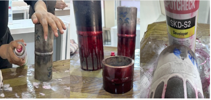
After welding, all joints were first subjected to visual inspection to identify any visible surface discontinuities. Liquid penetrant testing (PT) was then performed using the Magnaflux Spotcheck system, including SKC-S cleaner/remover, SKL-SP2 visible red penetrant, and SKD-S2 developer. The inspection procedure consisted of surface cleaning, penetrant application with a dwell time of approximately 10 min, removal of excess penetrant, followed by the application of the developer for approximately 10 min before visual evaluation. The inspection procedure was carried out in accordance with the general principles of ASTM E165/E165M, while the weld acceptance was assessed according to API 1104 [16, 17].
Figure 6. The procedure of liquid penetrant testing (PT)
Table 4. Summary of visual and dye penetrant inspection results
|
Joint Type |
Surface Cleaning |
Penetrant Application Time (min) |
Developer Type |
Developer Time (min) |
Inspection Result |
|
SS–SS |
Surface cleaned and dried according to the procedure described in Section 2.5 |
10 |
Wet Developer |
10 |
No relevant surface indications detected |
|
CS–SS |
Surface cleaned and dried according to the procedure described in Section 2.5 |
10 |
Wet Developer |
10 |
No relevant surface indications detected |
The main stages of the inspection procedure are illustrated in Figure 6, and the inspection results are summarized in Table 4.
2.6 Metallographic preparation
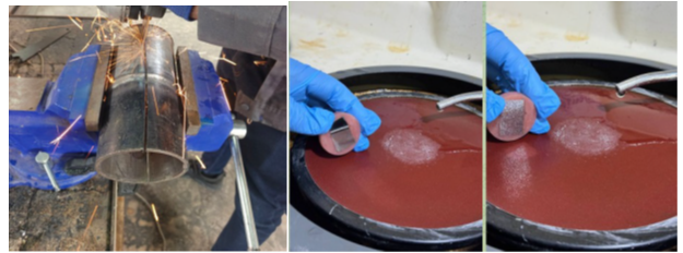
Transverse sections were cut from the welded joints of the three joint configurations (CS–CS, SS–SS, and CS–SS) for metallographic examination. We prepared the specimens using standard metallographic procedures. Grinding was performed sequentially using silicon carbide abrasive papers with grit sizes of 240, 400, 600, 800, 1000, and 1200, followed by mechanical polishing to obtain a mirror-like surface, as shown in Figure 7.
The CS–CS specimens were etched using a commercially prepared Nital reagent, while the SS–SS and dissimilar CS–SS specimens were etched using a commercially prepared Glyceregia reagent. Glyceregia was selected for the dissimilar joint because it provided adequate contrast for revealing the fusion boundary and the adjacent microstructural regions without excessive attack on the SS side. The etching time for all specimens was approximately 10 s.
We performed optical microstructural examinations of all welded joints using an OPTIKA optical microscope equipped with a 10× objective lens (100× total magnification). To guarantee comparability between the observed areas, images of the BM, HAZ and WM were taken at the same magnification under the same observation conditions.
Figure 7. Metallographic preparation
2.7 Tensile testing
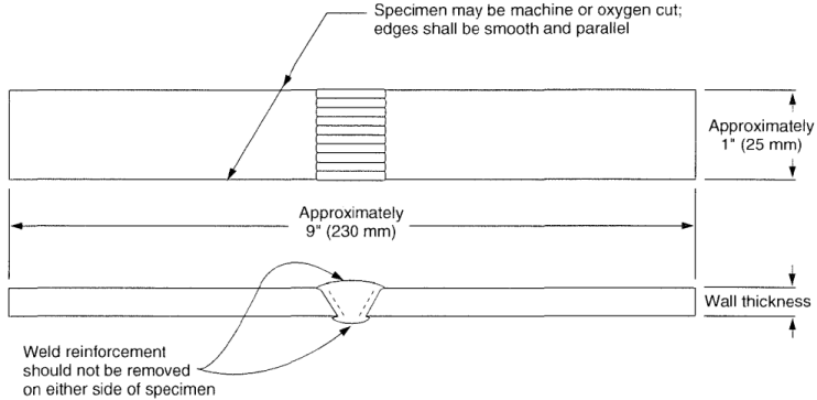
The tensile tests were performed as prescribed by API 1104 for pipeline girth welds [17]. From the welded pipes, transverse rectangular specimens were machined that contained the complete weld cross-section and the weld centerline was located near the center of the specimens. The geometry of the specimen is shown in Figure 8.
Figure 8. Dimensions of specimens [17]
The mechanical assessment was only done on the SS–SS and CS–SS joints; this is because the aim of this work is to investigate the effect of mismatch on tensile properties. Only the CS–CS joint was retained for microstructural comparison.
Three specimens were tested for each mechanically evaluated joint configuration with a Hira Universal Testing Machine at a crosshead speed of 20 mm/min and the generated engineering stress-strain curve was averaged across the three specimens to report the tensile properties. Following the test, the fracture area was inspected to determine the area of failure with respect to the WM and HAZ.
3.1 Non-destructive examination
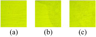
Visual inspection followed by PT was performed to evaluate the surface quality of the welded joints. Representative inspection results are shown in Figure 9. No relevant surface indications, such as surface cracks or open porosity, were detected in either the SS–SS or the CS–SS welded joints. According to the applied inspection procedure and the acceptance requirements of API 1104 [17], the examined welds satisfied the acceptance criteria for surface discontinuities under the selected welding conditions.
Figure 9. Visual inspection and liquid penetrant testing (PT) results
These results indicate that the selected TIG welding parameters produced sound weld surfaces suitable for subsequent metallographic and mechanical evaluation.
3.2 Tensile behavior
Tensile testing was limited to the SS–SS and CS–SS configurations, as the main objective of this study was to evaluate the effect of material mismatch on mechanical response. The CS–CS joint was excluded from mechanical testing and used mainly for structural comparison. Therefore, the discussion of tensile properties is restricted to the mechanically tested configurations.
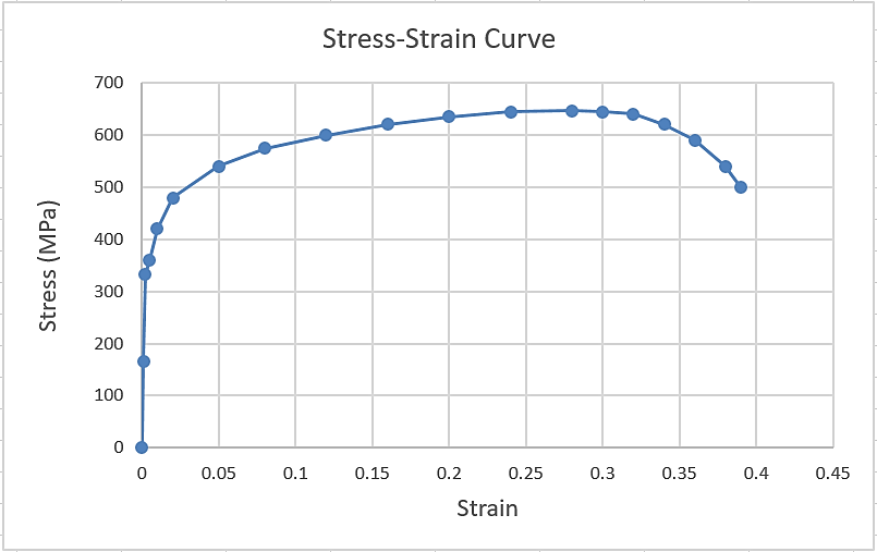
The stress–strain response of the SS–SS joint indicated a typical ductile behavior. The ultimate tensile strength (UTS) was found to be approximately 647 MPa, accompanied by an elongation of about 39%. A noticeable strain hardening stage developed prior to fracture, which is consistent with the behavior of austenitic SS.
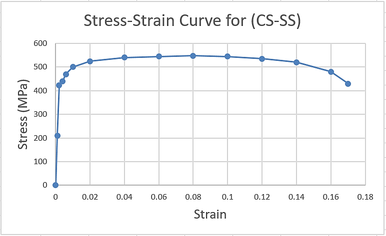
While the UTS of the CS–SS joint decreased to around 548 MPa, the elongation fell to nearly 17%. While the yield strength (YS) looked slightly higher than that of the SS–SS joint, the total plastic deformation ability was more limited. This drop in ductility may be attributed to the mismatch in mechanical properties between CS and SS, as well as the microstructural changes occurring in the HAZ.
The stress–strain curves of the two joints are presented in Figures 10 and 11. The tensile properties got from the experimental tests are summarized in Table 4.
Table 5. Average tensile properties of the welded joints obtained from three specimens for each configuration (n = 3)
|
Type of Joint |
Yield Strength (YS), MPa |
Ultimate Tensile Strength (UTS), MPa |
Elongation, % |
UTS/YS Ratio |
|
SS–SS (316L–316L) |
332 |
647.6 |
39 |
1.95 |
|
CS–SS (API 5L–316L) |
422 |
548.8 |
17 |
1.30 |
Note: The values reported in Table 5 represent the arithmetic mean of three tensile specimens for each joint configuration (n = 3). The original individual test records required to calculate the standard deviation were not available at the time of manuscript revision; therefore, only the average values are reported.
The differences in the microstructural and mechanical properties of the two materials can be seen by comparing the elongation and UTS of the two joints in Table 5, where the SS–SS joint has the best ductility, while the CS–SS joint has the lowest. The tensile test results indicate that the welded joints have satisfactory mechanical properties for the given test conditions.
3.3 Fracture behavior
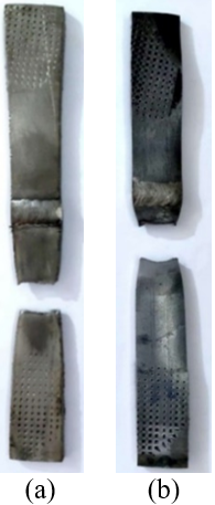
The fracture location for the SS–SS joint was in the middle of the necking that was very pronounced before the fracture, while the fracture location of the CS–SS joint was in the middle of the necking that was not so pronounced because its elongation was lower, as was obtained from the tensile test. Representative fractured specimens for both joint configurations are shown in Figure 12. The observed fracture characteristics are consistent with the tensile behavior and the microstructural features described in the following section.
Figure 12. Representative tensile-tested specimens after fracture: (a) Stainless steel–stainless steel (SS–SS) joint and (b) carbon steel–stainless steel (CS–SS) joint
3.4 Microstructural observations
3.4.1 Microstructural analysis of carbon steel–stainless steel joint
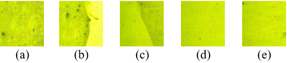
Figure 13 illustrates the locations from which the optical micrographs were obtained across the dissimilar CS–SS welded joint, including the CS BM, CS HAZ, WM, SS HAZ, and SS BM. The corresponding microstructures are presented in Figure 14.
The dissimilar CS–SS joint exhibited a distinct microstructural transition across the weld region. The CS BM displayed the typical ferrite–pearlite microstructure characteristic of low-CSs, whereas the SS BM retained its fully austenitic structure. Noticeable grain coarsening was observed within the HAZ on the CS side as a result of the welding thermal cycle, while the SS HAZ showed only limited microstructural changes. The WM exhibited a predominantly austenitic solidification structure, consistent with the use of the ER309L filler metal. Overall, the observed microstructural characteristics were in agreement with the different tensile behaviors obtained for the CS–SS and SS–SS welded joints.
3.4.2 Microstructural analysis of carbon steel–carbon steel joint
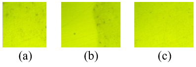
The microstructure of the CS–CS welded joint in Figure 15 exhibited a gradual transition across the BM, HAZ, and WM. The BM displayed the typical ferrite–pearlite microstructure of CS. Grain coarsening was observed in the HAZ as a result of the welding thermal cycle, while no obvious phase transformation was identified. The WM exhibited a relatively uniform solidification structure without visible welding discontinuities. Overall, the microstructural observations indicated acceptable weld quality under the selected welding conditions.
3.4.3 Microstructural analysis of stainless steel–stainless steel joint
The microstructure of the SS–SS welded joint in Figure 16 remained relatively uniform across the examined regions. The BM exhibited the typical fully austenitic microstructure of AISI 316L SS. Slight grain growth was observed within the HAZ after welding, while the overall austenitic structure remained stable. The WM exhibited a predominantly austenitic solidification structure, consistent with the use of the ER309L filler metal. Overall, the microstructural observations indicated good metallurgical compatibility and stable welding conditions.
3.4.4 Comparative microstructural–mechanical analysis
A clear difference was observed between the mechanically tested similar (SS–SS) and dissimilar (CS–SS) welded joints. The comparison was limited to these two configurations because tensile testing was performed only for them. The SS–SS joint exhibited higher ductility and more stable plastic deformation than the CS–SS joint, which is consistent with the tensile test results. Optical microscopy (OM) revealed noticeable microstructural variations across the dissimilar joint, particularly between the CS BM, HAZ, and WM. These variations are consistent with the lower ductility and UTS measured for the CS–SS joint. The observed tensile behavior is consistent with the microstructural variations identified across the welded joint. However, local hardness measurements were not included in the present investigation; therefore, the present interpretation is based on the combined evidence obtained from tensile testing and OM.
The present study focused on the mechanical evaluation of the SS–SS and CS–SS welded joints, whereas the CS–CS joint was included only for microstructural comparison. A limitation of the present study is that microhardness profiling was not performed; therefore, local hardness variations across the WM, HAZ, and BM could not be quantitatively correlated with the tensile behavior. Consequently, the present interpretation of material mismatch is based on the combined evidence obtained from tensile testing and OM.
Future work will include microhardness profiling together with tensile evaluation of the CS–CS joint to provide a more comprehensive comparison among the three welded joint configurations.
Based on the experimental findings, the main conclusions of this study can be summarized as follows:
(1) Sound welded pipe joints were successfully produced using the TIG welding process with ER309L filler metal for the SS–SS, CS–SS, and CS–CS joint configurations, without visible surface welding defects.
(2) The SS–SS joint had the best tensile properties with the average YS of 332 MPa, the UTS of 647.6 MPa and the elongation of 39%. The corresponding tensile strength, YS and ductility of the CS–SS joint were 422 MPa, 548.8 MPa and 17%, respectively, which were lower than those of the other joints.
(3) Optical microstructural examination showed significant differences between the WM, HAZ and BM. The dissimilar joint exhibited greater microstructural heterogeneity than the similar SS joint, particularly near the CS side.
(4) The combined tensile and microstructural results indicate that material mismatch influences the mechanical response of the dissimilar welded joint, leading to reduced ductility and lower UTS compared with the SS–SS joint.
(5) The present study provides experimental data on TIG welding of similar and dissimilar pipe joints. Mechanical evaluation was limited to the SS–SS and CS–SS joints, whereas the CS–CS joint was included as a baseline reference for microstructural comparison.
The authors would like to acknowledge the Department of Petroleum Equipment Inspection and Welding Techniques, Kut Technical Institute, Middle Technical University and for providing the required facilities and assistance.
During the preparation of this work, the authors used ChatGPT in order to assist with language editing and sentence rephrasing to improve the readability of the manuscript. After using this tool/service, the authors reviewed and edited the content as needed and take full responsibility for the content of the published article.
|
D |
Pipe outside diameter, mm |
|
El |
Elongation at fracture, % |
|
ER309L |
Austenitic stainless steel filler metal |
|
L |
Gauge length of tensile specimen, mm |
|
t |
Pipe wall thickness, mm |
|
UTS |
Ultimate tensile strength, MPa |
|
YS |
Yield strength, MPa |
|
Greek symbols |
|
|
ε |
Engineering strain, dimensionless |
|
σ |
Engineering stress, MPa |
|
Abbreviations |
|
|
AISI |
American Iron and Steel Institute |
|
API |
American Petroleum Institute |
|
ASTM |
American Society for Testing and Materials |
|
BM |
Base Metal |
|
CS |
Carbon Steel |
|
SMAW |
Shielded Metal Arc Welding |
|
DMW |
Dissimilar Metal Welding |
|
GTAW |
Gas Tungsten Arc Welding |
|
HAZ |
Heat-Affected Zone |
|
NDT |
Non-Destructive Testing |
|
OM |
Optical Microscopy |
|
PT |
Liquid Penetrant Testing |
|
SS |
Stainless Steel |
|
MIG |
Metal Inert Gas |
|
TIG |
Tungsten Inert Gas |
|
WM |
Weld Metal |
[1] Oktadinata, H., Putra, A.G. (2019). Microstructure and hardness profile of dissimilar lap joint of type 304 stainless steel to SS400 carbon steel. Metal Indonesia, 41(2): 46-53. https://doi.org/10.32423/jmi.2019.v41.47-54
[2] Sabzi, M., Jafarian, H.R., Abdollahzadeh, A., Anijdan, S.M., Eivani, A.R. (2025). Continuous and pulsed TIG welded joint of ASTM A105-AISI 316L steels: Characterization of microstructure, mechanical properties, and fracture analysis. Journal of Materials Research and Technology, 39: 5440-5454. https://doi.org/10.1016/j.jmrt.2025.10.219
[3] Rogalski, G., Świerczyńska, A., Landowski, M., Fydrych, D. (2020). Mechanical and microstructural characterization of TIG welded dissimilar joints between 304L austenitic stainless steel and Incoloy 800HT nickel alloy. Metals, 10(5): 559. https://doi.org/10.3390/met10050559
[4] Huang, B.S., Yang, J., Lu, D.H., Bin, W.J. (2016). Study on the microstructure, mechanical properties and corrosion behaviour of S355JR/316L dissimilar welded joint prepared by gas tungsten arc welding multi-pass welding process. Science and Technology of Welding and Joining, 21(5): 381-388. https://doi.org/10.1080/13621718.2015.1122152
[5] Khan, R., Das, U., Pathak, A.K., Tiwari, D. (2016). Study of microstructure and mechanical properties of feritic stainless steel (AISI 430) weldment using ER309L and ER430 electrodes by MIG welding process. International Journal of Engineering Research & Technology, 5(1): 312-318. https://doi.org/10.17577/IJERTV5IS010336
[6] Soleimani, M.M., Mostafaei, H. (2024). The effect of filler metal on the mechanical behavior of stainless steel welded by GTAW welding. Iranian Journal of Manufacturing Engineering, 11(4): 38-55. https://doi.org/10.22034/IJME.2024.458059.1961
[7] Tayeb, H.H., Seyedpour, S.S., Rafiaei, S.M. (2026). Correlation between the microstructure and mechanical properties of dissimilar AISI 309 and 430 stainless steel joints welded via pulsed GTAW. Results in Materials, 29: 100905. https://doi.org/10.1016/j.rinma.2026.100905
[8] Güzey, B.N., İrsel, G. (2023). Investigation of mechanical and microstructural properties in joining dissimilar P355GH and stainless 316L steels by TIG welding process. International Journal of Pressure Vessels and Piping, 205: 104965. https://doi.org/10.1016/j.ijpvp.2023.104965
[9] Zhang, T., Shuai, Y., Shuai, J., et al. (2024). Study on fracture behaviour of pipeline girth welds based on curved wide plate specimens: Experimental and numerical analysis. Engineering Fracture Mechanics, 311: 110522. https://doi.org/10.1016/j.engfracmech.2024.110522
[10] Krishnan, S.A., Nikhil, R., Parnaik, A., Moitra, A., Vasudevan, M. (2024). Investigation on fracture resistance behaviour of dissimilar metal weld joint of modified 9Cr–1Mo steel and AISI 316LN SS. International Journal of Pressure Vessels and Piping, 211: 105260. https://doi.org/10.1016/j.ijpvp.2024.105260
[11] Touileb, K., Djoudjou, R., Hedhibi, A.C., et al. (2022). Comparative microstructural, mechanical and corrosion study between dissimilar ATIG and conventional TIG weldments of 316L stainless steel and mild steel. Metals, 12(4): 635. https://doi.org/10.3390/met12040635
[12] Touileb, K., Hedhibi, A., Djoudjou, R., Ouis, A., Bouazizi, M.L. (2019). Mixing design for ATIG morphology and microstructure study of 316L stainless steel. Engineering, Technology & Applied Science Research, 9(2): 3990-3997. https://doi.org/10.48084/etasr.2665
[13] Sharma, P., Dwivedi, D.K. (2019). A-TIG welding of dissimilar P92 steel and 304H austenitic stainless steel: Mechanisms, microstructure and mechanical properties. Journal of Manufacturing Processes, 44: 166-178. https://doi.org/10.1016/j.jmapro.2019.06.003
[14] Aulia, Y.T., Ariyon, M., Fitriani, F., Sebayang, A., Tarigan, E. (2025). Comparative analysis of tensile strength of steel tubing pipe welding results using SMAW and MIG welding with 140A current. International Journal of Engineering, Science and Information Technology, 5(1): 140-144. https://doi.org/10.52088/ijesty.v5i1.645
[15] Hasein, A.N., Aned, A.M., Razzaq, M.K.A. (2023). Identifying some regularities of the heat transfer in the welded joint of SUS304 pipe using a numerical approach. Eastern-European Journal of Enterprise Technologies, 5(1): 104-113. https://doi.org/10.15587/1729-4061.2023.290124
[16] ASTM E165/E165M. (2023). Standard Practice for Liquid Penetrant Testing for General Industry. ASTM International, West Conshohocken, PA, USA. https://doi.org/10.1520/E0165_E0165M-23
[17] API 1104. (2001). Welding of Pipelines and Related Facilities. American Petroleum Institute. https://store.accuristech.com/standards/api-1104?product_id=2056.