Hameed Obaid Radhi* | Sheyan Abdallhh Rashied
© 2026 The authors. This article is published by IIETA and is licensed under the CC BY 4.0 license (http://creativecommons.org/licenses/by/4.0/).
OPEN ACCESS
This study introduces a high-fidelity numerical study of the structural and dynamic optimization of hybrid composite pipes, including a 5 mm carbon/epoxy pipe as the inner core (substrate) and a polyethylene-based outer laminate shell, under a 20 MPa internal pressure. The research considers three different placement orders: 2, 5, and 10 layers to assess the transition between simple and high-performing quasi-isotropic reinforcement. The results of the structural analysis show a non-linear relationship between ply count and radial expansion. The 10-layer [0/45/90/135/180/225/270/315/0/0] design obtained a 15% decrease in total deformation, from 1.239 mm to 1.053 mm. Such stabilization is achieved through a combination of the "total" wall thickness and the 90° hoop reinforcement, in which the high-modulus carbon/epoxy core is circumferentially reinforced to provide the desired strain support. Moreover, through the 10-layer design, the safety-critical boundary stress spikes were well controlled to about 1350 MPa, showing significantly improved load shifting off the constraint. The vibrational performance was assessed using a prestressed eigenvalue problem, which showed a 3.5% reduction in the maximum vibrational deformation of the 10-layer assembly. Under such high-pressure conditions, it was important to introduce a stress-stiffness matrix to accurately mimic dynamic resistance. Finally, a possible design guideline is presented to reduce boundary stress singularities from severe to reasonable levels without compromising the structural performance of the high-pressure industrial pipeline, transitioning from a basic cross-ply to a 10-layer quasi-isotropic architecture. While simpler configurations are structurally inadequate under dynamic loading, the 10-layer configuration may offer improved load redistribution, comparable compliance, and enhanced stability.
pre-stressed modal analysis, hoop stress reinforcement, carbon/epoxy and polyethylene laminates, edge effect stress spikes, vibrational stability
Unlike conventional metallic systems, composite pipes and pressure vessels have higher specific strength and corrosion resistance, and are more design-flexible. Therefore, they have been significant objects of research during the last few decades. The parameters that significantly affect the structural performance of these parts include the winding angle, stacking order, material anisotropy, and environmental exposure. This has led to extensive research on how they respond to internal pressure, bending, and hot loading during dynamic loading. Advanced numerical prediction techniques, such as finite element modeling, have been used to predict the burst pressure and deformation behavior. In addition, multiscale and homogenization methodologies have been developed to measure effective ply properties and incorporate prestressing effects into the manufacturing process. Nonetheless, even with these developments, it has posed a research challenge: how to optimize structural efficiency while accurately predicting failure mechanisms. Thus, it is necessary to thoroughly evaluate prior research to identify knowledge gaps and to inform the design of more effective analytical and design techniques for filament-wound composite structures.
Ilinca et al. [1] experimentally analyzed the stress-strain behavior of caviar filament-wound Glass Fiber Reinforced Polymer (GFRP) pipes under internal pressure. They measured stresses (axial and hoop) using tensile and bending tests, as well as full-scale tests with strain gauges. The findings validated a predominantly adhesive reactive conduct and a hoop-dominated conduct. The research verified the ISO 14692 permissible-stress design assumptions by comparing them with direct experimental data. Toh et al. [2] proposed an inverse stress-homogenization approach to estimate ply-level mechanical characteristics of filament-wound FRP pipes from experimentally obtained global responses. It combines an initial estimation based on micromechanics with a refinement via finite element simulations. Validation was performed using standardized tensile, compression, and ring-stiffness tests. The experiment indicated that the ply properties obtained can accurately predict the behaviour of pipes with various geometries.
Yin [3] developed a multiscale homogenization framework to predict comparable elastic characteristics of filament-wound composite tubes, accounting for fiber-winding prestressing. The study assessed the effects of thermal residual stresses and fiber pretension on the axial modulus and geometric stability by incorporating these effects into a modified bridging model. The model was a quasi-three-dimensional laminate theory, coupled with thermal and mechanical alignment. It was found that the predicted outcome was in good agreement with the experimental references, indicating that it can be used to design prestressed composites. Yarashev et al. [4] studied the natural oscillation behavior of curved pipes filled with multilayer composite under pressure. Numerical computations reveal that one of the main factors influencing eigenfrequencies and vibration modes is the internal pressure. Stabla et al. [5] compared filament-wound composite pipes with mosaic winding patterns subjected to radial compression. They used Hashin's damage considerations via finite element modeling, yielding a very explicit expression for zig-zag interweaving areas. It was found that winding patterns influence stress distribution, stiffness reduction, and failure mechanisms. The paper highlights the importance of realistic geometric modeling for predicting the strength of composite pipes. Ouarhim et al. [6] conducted a detailed review of the development, processing, and mechanical properties of natural fiber-based thermosetting composites. They also studied that raw natural fibers generally have high hydrophilicity, which makes the fiber/polymer interfaces vulnerable due to the inferior bonding properties. The authors demonstrated this by carefully tuning the chemical surface treatments of the fibers (such as alkaline, silane, and acetylation) to improve fiber-matrix bonding. Through experimental and numerical studies, Huang et al. [7] investigated the flexural performance of large-scale Filament-wound Carbon Fiber Reinforced Polymer (CFRP) pipes. The various layup sequences were tested under four-point bending to determine their strength and failure mode. A progressive matrix and fiber-damage model, including a damage simulation, was developed. Findings established that the construction's stacking structure exerts a high degree of control over bending performance and failure behavior.
Ozbek [8] reviewed the mechanical performance of filament-wound hybrid composite pipes through intra-ply fiber hybridization. Tensile, axial, and radial compression and crushing tests and evaluations were conducted experimentally at different winding angles. The findings indicated that changes in fiber orientation alter hybridization, thereby affecting stiffness, strength, and energy absorption. The overall performance of the hybrid pipes was comparable to that of non-hybrid composites, providing a customized mechanical response. Guz et al. [9] investigated the distribution of stress and failure in thin-walled, multi-layer, filament-wound composite pipes under pressure and load conditions for offshore applications. An analytical formulation was used to compute radial, hoop, and axial stresses across the wall thickness based on orthotropic elasticity. The paper compared various lay-up structures to determine their effects on structural integrity. Results have also indicated that the winding angle and stacking sequence are very important for increasing pressure resistance and delaying failure.
Ha et al. [10] investigated the debonding behavior caused by interfacial cracks in sprayed FRP laminates bonded to reinforced concrete (RC) beams under four-point bending. The experimental data demonstrated that the fiber volume fraction and laminate thickness are also important factors for the crack load, debonding load, and failure mode. Four predictive models on intermediate crack (IC) debonding were compared with the measured strain values. The results showed scattered, observable predictions indicating a need for better models of debonding in sprayed FRP systems. Jiang et al. [11] developed an analytical model to estimate the three-point bending failure mechanisms of an aluminum foam-core sandwich beam. The model accounted for face yield, core shear, and indentation, taking into account the elastic properties of both constituents. The predicted failure modes and critical loads showed close agreement with the experimental results, and the proposed model outperformed the modified Gibson model in terms of accuracy. Alexander and Augustine [12] conducted a progressive failure analysis of pipes made of basalt/epoxy filament-wound composite under internal pressure. Using finite element modeling and a maximum-stress-based criterion, they determined the first- and last-ply failure pressures for basalt, glass, and hybrid systems. Findings indicated that burst performance is highly affected by ply orientation and blanket combination. The research indicated the relevance of modeling stiffness degradation in predicting the failure of composite pressure vessels.
Júniora et al. [13] examined the effect of environmental conditioning on the burst pressure of the carbon/epoxy filament-wound composite pipes. Using finite element modeling and hygrothermal coefficient evaluation, the authors evaluated winding angles from ±35° to ±75°. Their results indicated that the burst pressure peaked at approximately ±55°, then declined at angles beyond that, confirming that the optimal stress balance is approximately ±55°. Likewise, external influences (water and temperature) reduced the internal pressure capacity by 2–3%, underscoring the importance of durability in service conditions. Madhavi and Venkat [14] have formulated a three-dimensional finite-element prediction technique to govern the structural behaviour and the progressive-failure ideal of filament-wound composite pressure vessels with geodesic end domes. The experiment combined Classical Lamination Theory (CLT) and ply-wise progressive failure analysis to assess mattress fracturing and burst pressure at varied shell positions. Structural safety was evaluated using strength ratios and various failure criteria, including the Tsai-Hill and Tsai-Wu criteria. The suggested methodology served as an effective design validation tool for composite pressure vessels under internal pressure. Sulaiman et al. [15] conducted a finite-element study of filament-wound composite overwrapped pressure vessels (COPVs) under internal pressure across various vessel shapes. Using ABAQUS, the authors compared asymmetric fiber orientations from 0° to 90° and burst pressure and shell displacement using the Tsai-Wu, Tsai-Hill, and maximum stress failure criteria. Their findings showed that, as wave angle increases, the burst pressure rises to about 55° and then decreases, confirming that ±55° is the optimal arrangement. The experiment has shown good correlation between the numerical forecasts, experimental trends, and the classical netting analysis theory.
A special focus of the standard pressure-pipe design practice is the structural design of composite pipes under internal pressure, a field subject to strict standardization and homogenization. In an ISO standard, for example, ISO 14692, the permissible-stress design assumptions were validated by direct experimental correlation on GFRP pipes by Ilinca et al. [1]. To address the trade-off between global responses and local properties, Toh et al. [2] suggested an inverse stress-homogenization method, in which mechanical properties of each layer were estimated directly from standard testing. In addition, the use of advanced failure criteria is essential for predicting the mechanisms of yielding and fracture in an anisotropic material accurately [13]. For this, the effects of fiber-winding prestressing and thermal residual stresses in the material must be taken into account. Meanwhile, the following three steps will be performed to carry this out. Alexander and Augustine [12] used a finite element model with a maximum-stress criterion to determine accurate first- and last-ply failure in hybrid systems. Following the maximum stress criterion, Madhavi and Venkat [14] and Sulaiman et al. [15] used the interactive Tsai-Hill and Tsai-Wu failure criterion in a ply-wise progressive failure analysis: It was found that a winding angle of about 55° maximizes the burst pressure of composite vessels. Recently, Stabla et al. [5] added Hashin's damage to explicitly account for stiffness reduction and zig-zag interweaving damage under radial compression, thereby emphasizing the need for realistic geometric modeling to capture failure.
To put this numerical study in perspective for practical engineering applications, an applied internal pressure of 20 MPa (about 200 bar) was chosen to reflect the most severe engineering conditions in the petroleum, natural gas, and offshore industries. It is a pressure level typical of deep-water subsea risers, high-pressure flowlines, and compressed-fluid storage vessels. In addition, the particular hybrid material construction (carbon/epoxy core with a polyethylene outer shell) was selected to consider both structural and cost industrial constraints. Manufacturing the pipeline with thick walls using a 5 mm inner carbon/epoxy core for critical load-bearing tensile strength would be prohibitively expensive using aerospace-grade carbon/epoxy material. As such, it is highly cost-effective to package the core with a multi-layered composite shell of polyethylene, which will add much-needed geometric bending stiffness, spread hoop stresses, and add excellent environmental corrosion and impact protection for harsh offshore applications.
The main contributions of the present research are clearly stated as follows, which represent the current lack in high-pressure composite modelling:
(1) Mathematical quantification of the non-linear relationship between layer accumulation and global structural compliance, which has confirmed that a 10-layer quasi-isotropic polyethylene shell can reduce the total radial deformation by 15% over a commercial 2-layer baseline.
(2) Showing that it is possible to effectively reduce severe boundary stress singularities around fixed connections of pipelines using dedicated 90° hoop reinforcement and geometric stiffness driven by a thickness increase in the pipe section.
(3) The dependence of the pre-stress-stiffness matrix (S) is essential for a reliable prediction of the dynamic stability of pressurized composites, and it is shown that the added mass of the pre-stressed 10-layer assembly is an important dynamic damper that attenuates the response to high-frequency oscillatory swings.
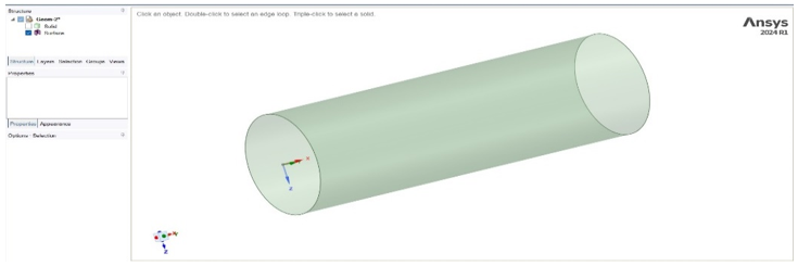
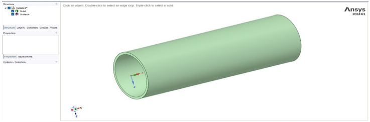
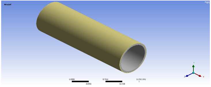
The composite pipe discussed in this section is a two-region cylindrical design with an internal structural carbon/epoxy layer. A versatile polyethylene-based composite laminate is an outer multilayer laminate with variable ply numbers and orientations. It is assumed that the pipe is straight, axisymmetric, and operates under high-pressure conditions. The ANSYS model was designed using ANSYS SpaceClaim. The model was 350 mm long, with an inner diameter of 65 mm, a 5 mm-thick inner carbon/epoxy layer, and a variable outer diameter of a polyethylene-based composite ranging from 71 mm to 80 mm, according to the ply numbers on the outer surface of the pipe. The inner diameter is designed as a solid part in ANSYS SpaceClaim. In contrast, the outer layer is designed as a surface to control its thickness later during the simulation process and to transform it separately into the ACP ANSYS model. Figure 1 shows the simulation geometry designed in ANSYS SpaceClaim and its final design after finishing the ACP setup parameters and combining both models. Table 1 shows the mechanical properties of the simulation model for the two materials.
(a) Pipe surface design
(b) Pipe solid design
(c) Complete pipe model after ACP mode completion
Figure 1. ANSYS model geometry design
Table 1. Mechanical properties of carbon/epoxy and polyethylene composite
|
Property |
Carbon/Epoxy (Typical Range) |
Polyethylene Composite (Typical Range) |
|
Density (kg/m³) |
1550 |
930 |
|
Longitudinal Young’s Modulus E1 (GPa) |
130 |
10 |
|
Transverse Young’s Modulus E2 (GPa) |
8 |
1.2 |
|
In-Plane Shear Modulus G12 (GPa) |
5 |
0.4 |
|
Major Poisson’s Ratio ν12 |
0.25 |
0.4 |
|
Tensile Strength Longitudinal (MPa) |
1200 |
200 |
|
Tensile Strength Transverse (MPa) |
60 |
30 |
|
Compressive Strength Longitudinal (MPa) |
1000 |
150 |
|
Shear Strength (MPa) |
80 |
20 |
|
Coefficient of Thermal Expansion α1 (10⁻⁶/℃) |
1 |
110 |
|
Coefficient of Thermal Expansion α2 (10⁻⁶/℃) |
30 |
150 |
|
Thermal Conductivity Longitudinal (W/m·K) |
8 |
0.4 |
|
Thermal Conductivity Transverse (W/m·K) |
1 |
0.35 |
Table 2. The individual ply thickness and the total outer wall thickness for all three configurations
|
Configuration |
Individual Ply Thickness |
Total Outer Polyethylene Wall Thickness |
Total Outer Pipe Diameter |
|
2-Layer [0/45] |
0.5 mm |
1 mm |
76 mm |
|
5-Layer [0/45/90/135/180] |
0.5 mm |
2.5 |
77.5 mm |
|
10-Layer [0/45/90/135/180/225/270/315/0/0] |
0.5 mm |
5 |
80 mm |
Table 2 provides the exact individual and total thicknesses of the polyethylene outer shell for each of the three simulated composite pipe configurations. It shows that the intrinsic expansion of the total wall thickness contributes to the increasing complexity of the layup from 2 to 10, as does the quasi-isotropic model, with a maximum outside diameter of 80 mm. This data precisely quantifies these dimensions and clarifies the interplay between the addition of structural reinforcement plies and the natural increase in geometry during production.
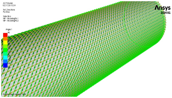
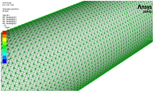
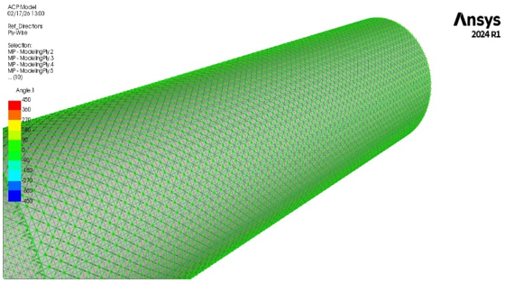
The numerical simulation in this research included three ANSYS modes: the geometry created using ANSYS SpaceClaim as explained above, and two copies of this design, which were used with the ACP and mechanical modes in ANSYS, as explained sequentially in Table 3. The first ANSYS geometry model consists of the surface portion of the complete design, as illustrated in Figure 1(a), for use with the ACP mode. The second consists of the solid part used in the mechanical mode, as illustrated in Figure 1(b). Three ACP models were fabricated, each with 2, 5, and 10 layers. Using a 45° step, the layer orientations were determined. For the 10-layer model, this automated stepping within the ANSYS ACP module generated an initial angular sequence of (0°, 45°, 90°, 135°, 180°, 225°, 270°, 315°, 360°, 0°). The 9th and 10th plies are essentially the same ply, with added thickness in the 0° axial direction, since 360° is considered the same fiber direction as 0°. For mechanical clarity, this sequence is consistently denoted [0/45/90/135/180/225/270/315/0/0] in the rest of this study. Once the setup was complete, a solid body was formed within the ACP mode. The solid body in Figure 1(b) was transferred to the ANSYS mechanical mode to generate the mesh, and the materials for the pipe's internal part were assigned as Epoxy Carbon UD (230 GPa). The two final body parts from the ACP and mechanical modes were combined and transferred to the model section of the third part of this simulation (static structure), as illustrated in Figure 1(c), to calculate the effects of internal pressure on deformation and stress. Figure 2 illustrates the layers of the three investigated models in ACP mode, as explained above.
Table 3. Three-level numerical simulation procedure and data transfer logic
|
Step |
Process and Module |
Action and Data Transfer |
|
Level 1 |
ANSYS SpaceClaim |
Design Phase: Create a 350-mm-long pipe. Solid Body: Inner 5 mm carbon/epoxy layer. Surface Body: Outer polyethylene layer. |
|
|
|
Geometry Transfer: Sends surface to ACP and solid to mechanical. |
|
Level 2 |
ANSYS ACP (Pre) |
Composite Setup: Assign polyethylene fabric. Config 1: 2 layers (0, 45°). Config 2: 5 layers (0 to180°) with 45° step. Config 3: 10 layers (0 to 315° in 45° steps, followed by 0°). |
|
|
|
Solidification: ACP converts the surface layers into a solid composite body. |
|
Level 3 |
Mechanical / Static Structural |
Structural Analysis: Integrates both solid parts. Load: Apply 20 MPa internal pressure. Output: Calculate deformation and stress. |
|
|
|
Solution Transfer: Structural data is sent to the modal system. |
|
Final |
Modal Analysis |
Dynamic Analysis: Determine natural vibrations and eigenfrequencies under pressurized conditions. |
(a)
(b)
(c)
Figure 2. Ply layup and orientation for the three pipe models: (a) 2-layer pipe with orientations of 0° and 45°, (b) 5-layer pipe with orientations of 0°, 45°, 90°, 135°, and 180°, and (c) 10-layer pipe with a stacking sequence of [0/45/90/135/180/225/270/315/0/0]
The tabular recording of these protocols for data transfer, i.e., transforming surface bodies into solidified layers of composite, ensures the reproducibility of the simulation, and internal pressure effects are factored out during vibration analysis to determine the pipe's eigenfrequencies. Table 4 below details the orientations and thicknesses of the ten investigated layer designs.
Table 4. Configuration of the composite pipe layup sequences
|
Model |
Component |
Material |
Ply Orientations |
Total Component Thickness |
|
2-Layer Model |
Inner Core |
Carbon/Epoxy |
N/A (Solid Body) |
5 mm |
|
Outer Shell |
Polyethylene |
[0° / 45°] |
Variable |
|
|
5-Layer Model |
Inner Core |
Carbon/Epoxy |
N/A (Solid Body) |
5 mm |
|
Outer Shell |
Polyethylene |
[0° / 45° / 90° / 135° / 180°] |
Variable |
|
|
10-Layer Model |
Inner Core |
Carbon/Epoxy |
N/A (Solid Body) |
5 mm |
|
Outer Shell |
Polyethylene |
[0° / 45° / 90° / 135° / 180° / 225° / 270° / 315° / 0° / 0°] |
Variable |
In ANSYS ACP simulations, mesh independence tests are essential to ensure consistent results across varying mesh densities. The central goal is to determine the optimal mesh density that achieves good rendering performance without compromising accuracy. The differences in the results, testable by high-quality mesh independence, can be very large, and we perform extensive simulations with coarse, medium, and fine meshes to observe them. The independence of the mesh is evident from the fact that the results remain unchanged even after mesh refinement, despite a few modifications. The simulation was used to run an independence test on seven meshes with element sizes ranging from 1.5 mm to 5 mm in 0.5 mm increments. The element size largely determines the mesh resolution in this experiment. The number of mesh elements is greater than for smaller objects and less than for larger ones [16]. The initial measurement parameter obtained from the test analysis was the deformation output. The test results depend on the size of the mesh parts, as illustrated in Table 5. The model mesh included skewness and orthogonality values in the table, along with the number of elements and nodes used due to the deformation. Mesh independence must be verified in ANSYS simulations to ensure accurate, robust results. The test involves refining the grid to determine whether values such as deformation remain fixed during fine-tuning. They consider the computer's speed and accuracy when determining the most appropriate mesh size.
According to the data in Table 5, the simulation results indicate high stability as the mesh is refined from 1.5 mm to 5 mm, with a deformation output of 1.23 mm. The deformation output would be the same across the element size range of 1.5 mm to 3 mm, at 1.23 mm. The deformation values oscillate between 1.24 mm and 1.28 mm when the size exceeds 3 mm (3.5 mm to 5 mm), indicating that the less-accurate meshes are coarser. The convergence of the maximum stress values clearly justifies the choice of the element size 3.0 mm. The maximum stress decreases from 335.72 MPa to 285.86 MPa as the mesh size changes from 5.0 mm to 3.0 mm. Natural meshes are further refined to 2.5 mm and 2.0 mm, resulting in minimal variation in the calculated local stress values (284.72 MPa and 284.83 MPa, respectively), thereby validating the results of the 3.0 mm threshold, above which the mesh grid does not affect the calculated local stresses.
The optimum orthogonal quality (1.0) was obtained with a 3.0 mm element size. Although one might naturally expect that finer meshing would improve the results, in this thin-walled composite model the aspect ratio constraints of the individual plies caused mesh refinement beyond 3.0 mm to degrade element quality. This was confirmed by the skewness values, which increased with refinement, reaching 1.0 at a 1.5 mm mesh size (201,890 elements, nearly four times the number) without any corresponding change in the predicted deformation (1.23 mm). In particular, the skewness reaches a very undesirable value (1.0) when the mesh is finer at 1.5 mm, and the elements become collapsed and geometrically degenerated. The 3.0 mm mesh size is therefore considered optimal, as it provides convergence and maintains element geometry without the significant degeneration observed at finer mesh resolutions.
Table 5. Simulation model mesh independence test
|
Element Size |
Number of Elements |
Number of Nodes |
Skewness |
Orthogonality |
Deformation |
Peak Stress |
|
1.5 mm |
201890 |
806754 |
1 |
0.21 |
1.23 mm |
276.94 MPa |
|
2 mm |
148548 |
531938 |
0.93 |
0.63 |
1.23 mm |
284.83 MPa |
|
2.5 mm |
77979 |
270542 |
0.88 |
0.83 |
1.23 mm |
284.72 MPa |
|
3 mm |
54756 |
189594 |
0.79 |
1 |
1.23 mm |
285.86 MPa |
|
3.5 mm |
40200 |
139150 |
0.77 |
0.95 |
1.24 mm |
297.25 MPa |
|
4 mm |
30622 |
106679 |
0.76 |
0.91 |
1.26 mm |
311.83 MPa |
|
4.5 mm |
18564 |
60600 |
0.67 |
0.88 |
1.25 mm |
320.06 MPa |
|
5 mm |
14841 |
48832 |
0.52 |
0.74 |
1.28 mm |
335.72 MPa |
(a) Surface part
(b) Solid part
(c) Complete model
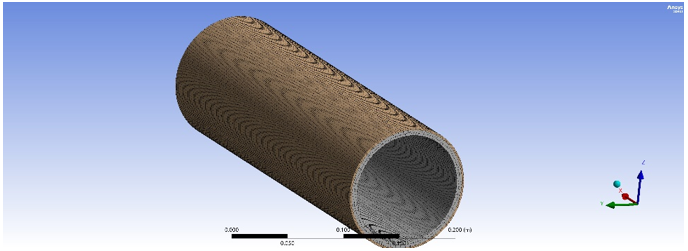
Figure 3. Simulation model mesh with 3 mm element size
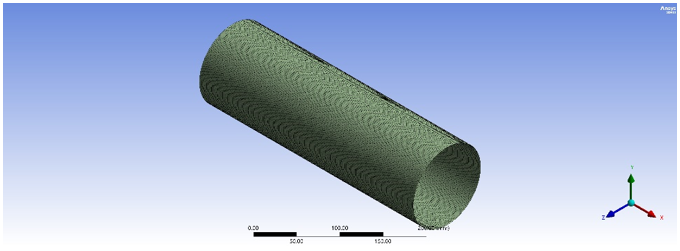
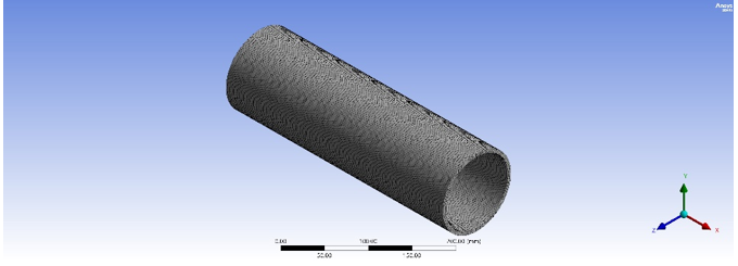
This mesh convergence study primarily aims to determine a mesh density at which the results are constant, while accounting for computer processing speed as finer tuning is applied. The 3.0 mm element size is the most efficient and effective in this simulation because it is the largest (coarsest) element size that achieves convergence, with a deformation value of 1.23 mm. It offers an optimal value of orthogonality of 1.0, which is important in the mathematical precision of the finite element solver. It has 54,756 elements and is therefore as precise as the 1.5 mm mesh (which contains more than 200,000 elements), but it requires much less computational effort. The deformation results start to vary (e.g., 1.24 mm at 3.5 mm) at 3 mm or above, as that is the mesh-independence clearance. Figure 3 illustrates the surface mesh, the solid mesh, and the complete model.
Defining boundary conditions is a highly important step in finite element analysis (FEA), as it determines how the mathematical model interacts with its surroundings. The boundary conditions used in this simulation are carefully designed to model a high-pressure environment, and the sophisticated interactions among the material, the internal structural layer, and the external composite reinforcement are also accounted for. The main load is an internal pressure of 20 MPa, applied as a normal force to the inner surface of the carbon/epoxy layer. On the expert simulation front, this has been considered in the static structural module environment to test the linear-elastic response of the hybrid assembly [17]. It is this pressure that drove the 1.23 mm deformation observed during the mesh independence phase. A more advanced value of the given simulation is the pre-stress correlation between the static structural and the vibration modal system. The stress-stiffness matrix is determined using the structural solution, which contains the state of stress (created by a 20 MPa load). This boundary condition is required because internal pressure substantially affects the pipe's stiffness; without this connection, the natural vibrations obtained after each calculation would lack accuracy in a functioning pipe.
This study modelled the interface between the pipe and the boundaries, using carefully drawn boundaries to reflect this. The pipe was constrained by fixing one end, thereby removing all 6 degrees of freedom. At its other end, a support was fastened to it so that it could be freely translated in the direction of the longitudinal axis to permit the axial expansion caused by the internal pressure, but would not allow the slightest translation in the radial direction and was restricted from any rotation on its longitudinal axis. The model assumes that the inner carbon/epoxy solid is perfectly bonded to the outer polyethylene-solidified composite body. This ensures the flow of strain and stress across the material's boundary and prevents slip. All the composite layers are assumed to be linearly elastic and orthotropic in both the static structural and modal analyses.) Influence of sequence of stacking: The boundary conditions have been tested using three different stacking sequences (2, 5, and 10 layers), in which the orientations (between 0° and 360°) determine the distribution of the pressure load across the polyethylene fibers.
The governing equations in the study can be divided into constitutive relations for the composite layers, structural equilibrium for the static analysis, and the eigenvalue problem for the modal analysis. The equations would apply to a three-layered model (2), a five-layered model (5), and a ten-layered model (10), and the variation in the outcomes would be determined by the specific combination of individual ply characteristics. In all three models, the orthotropic properties of the carbon/epoxy and polyethylene layers govern the relationship between applied stress and resulting strain. The ABD Matrix defines the built-in stiffness [18]:
$\left[\begin{array}{c}N \\ M\end{array}\right]=\left[\begin{array}{ll}A & B \\ B & D\end{array}\right]\left[\begin{array}{c}\epsilon^0 \\ K\end{array}\right]$ (1)
where,
Extensional stiffness (Aij) represents the summation of the stiffness of all the layers (k) divided by the total number of plies (2, 5, 10) and is expressed by the following equation [18, 19]:
$A_{i j}=\sum_{k=1}^n\left(\bar{Q}_{i j}\right)_k\left(Z_k-Z_{k-1}\right)$ (2)
where,
$[K]\{u\}=\{F\}$ (3)
where,
$\left([K]+[S]-w^2[M]\right)\{\emptyset\}=0$ (4)
where,
Table 6 below illustrates how stiffness accumulates mathematically according to the stacking sequences and material properties previously defined in the research [21].
Table 6. Comparative theoretical analysis of stiffness of varied ply distributions in extensional mode
|
Model Attribute |
2-Layer Model |
5-Layer Model |
10-Layer Model |
|
Stacking Sequence |
0°/45° |
0°/45°/90°/135°/180° |
0°/45°/.../0° |
|
Stiffness Summation (Aij) |
$\sum_{k=1}^2\left(\bar{Q}_{i j}\right)_k t_k$ |
$\sum_{k=1}^5\left(\bar{Q}_{i j}\right)_k t_k$ |
$\sum_{k=1}^{10}\left(\bar{Q}_{i j}\right)_k t_k$ |
|
Mechanical Goal |
Basic reinforcement for axial and shear loads. |
Increased hoop and transverse resistance. |
Full quasi-isotropic behavior across all planes. |
|
Fiber Contribution |
Limited to two discrete angles; results in lower overall stiffness. |
Distributes stress more evenly over 180° of orientation. |
Maximum load redistribution for the 20 MPa pressure. |
|
Thickness Effect |
Thinnest outer wall; smallest Aij terms. |
Intermediate thickness and stiffness. |
Thickest outer wall (Do = 80 mm); highest Aij terms. |
7.1 Deformation results analysis
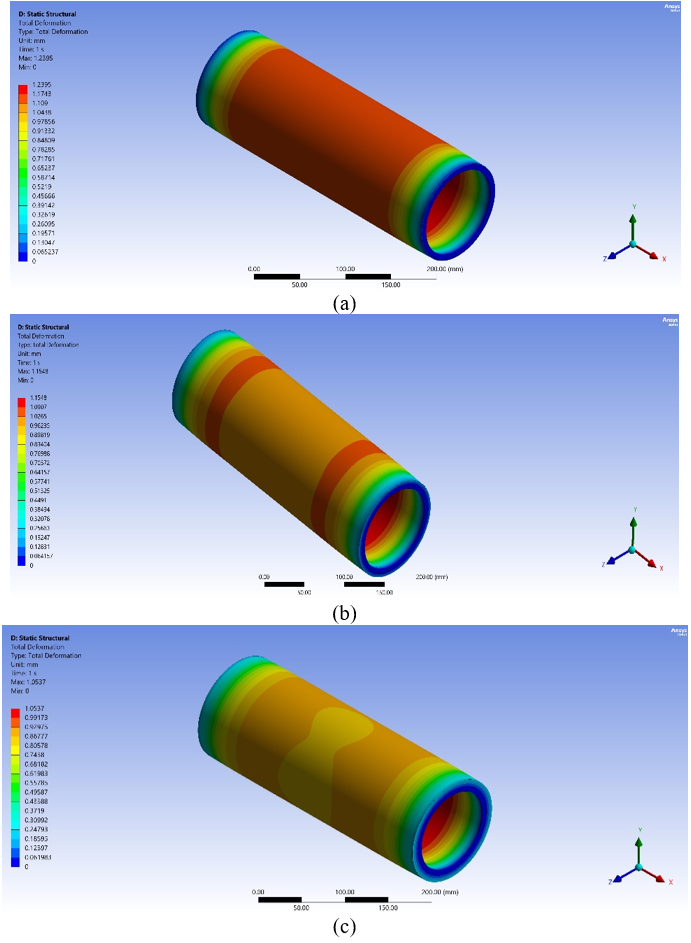
The deformation of a composite pipe under 20 MPa interior pressure provides clear evidence of the fundamental connection between laminate stacking arrangement and the allocation of ply directions and distributions, as illustrated in Figure 4 and as characterized by CLT. In the 2-ply setup (0°/45°), there is no special ply to provide circumferential stiffness. As a result, the hoop stress from internal pressure is insufficient, leading to the greatest deformation (1.2395 mm). By adding an extra 90° layer to the laminate (0°/45°/90°/135°/180°), the insertion of the 90° layer greatly increases the hoop stiffness. It redistributes stresses across the wall thickness, reducing anisotropic deformation and resulting in a total displacement of 1.1548 mm—quasi-isotropic behaviour in a 10-layer model.
The 10-layer model, denoted as [0/45/90/135/180/225/270/315/0/0], was designed to approximate quasi-isotropic behaviour. This stacking sequence will maximize extensional rigidity, as demonstrated by the A-matrix, and enhance bending rigidity, as the D-matrix will grow cubed with increasing thickness. Moreover, this configuration will reduce the B-matrix coupling effect. It thus has the smallest total deformation of 1.053 mm [22].
Figure 4. Deformation values and maps for composite pipes with (a) 2 layers, (b) 5 layers, and (c) 10 layers
It should be emphasized that the 15% reduction in total deformation across the models is the mechanical effect of the optimized quasi-isotropic fiber orientation, together with the proportional increase in the total outer wall thickness. If the structural capacity of a pipeline is required to be upgraded, the basic way to achieve this is to add more plies, i.e., to increase the number of plies of standard commercial thickness that are laid down. As a consequence, adding a second layer (axial and/or hoop reinforcement) is used to optimize stress redistribution and, at the same time, provides the additional benefit of increasing the outer wall's geometric bending stiffness (which scales as the cube of the thickness, according to D-matrix). Hence, the present structural analysis package accurately reflects this industrial practice, and it is found that maximum stability for the pressure vessel at 20 MPa is achieved through both the strategic complexification of the stacking sequence and the physical stacking of the laminate layers.
The cumulative buildup of contributions to transformed ply stiffness Qij is responsible for this gradual decrease in deformation, amounting to about 15% between 2 and 10 layers. Enhanced load redistribution in all directions, notably the opposition to the expansion of the hoop, and increased laminate thickness. More so, the high-modulus inner carbon/epoxy core gives high axial rigidity, and the main control of circumferential confinement lies with the many outer plies. The tighter and more stable the hybrid shell system becomes under pressure loading, the greater the mechanical efficiency. Thus, mechanically, the ANSYS outputs are consistent with both laminate theory and pressure vessel mechanics: the progressive increase in structural stiffness with additional layers and the relative angular variation in fiber orientations reduce radial deformation caused by high internal pressure [23].
Based on the governing equations in Section 6, Eq. (3) is the governing deformation equation of the global stiffness. Directly related to the laminate extensional matrix is K, as indicated in Eq. (2). Both equations demonstrate that deformation is governed by the number of layers (n), ply orientation (via the transformed stiffness matrix Qij), overall laminate thickness, and the coupling and bending stiffnesses. Figure 4 results indicate a rather sharp decrease of about 7% between 2 and 5 layers, about 8.7% between 5 and 10 layers, and a total of about 15% between 2 and 10 layers. As the results presented in Table 4 and Figure 4, the following equation is observed to add the ply numbers to the extensional stiffness [24]:
$A_{i j}=\sum_{k=1}^n \bar{Q}_{i j}^K t_k$ (5)
In Eq. (5), the increase of n results in an increase of the total wall thickness, the total integrated stiffness, the hoop resistance, and lastly in a decrease in the radial expansion. Since it is the inverse of the product of the stiffness and deformation, as is the case in the following equation:
$u=\frac{1}{A_{i j}}$ (6)
According to the above equations, two layers yield the lowest Aij and maximum deformation, whereas 10 layers yield the highest Aij and the lowest deformation. This tendency is absolutely consistent with CLT. The contribution of the stiffness of the ply is very dependent on the orientation of the ply about the main stress directions. The largest stresses will be the hoop stress (circumferential) and the axial stress, which is half the hoop stress (for a closed-end cylinder). In the case of thin-walled pressure vessels, these two values are determined as:
$Q_{\text {hoop}}=\frac{P r}{t}$ (7)
$Q_{\text {axial}}=\frac{P r}{2 t}$ (8)
The above two equations show that, in the 2-layer model (0/90), the 0-layer orientation will impose strong axial rigidity, and the 45-layer orientation will exhibit shear resistance, but does not have pure 90 hoop reinforcement. Thus, the hoop stiffness is limited. Circumferential expansion caused by pressure is large, and radial displacement is maximal (1.2395 mm). This design is structurally wasteful for pressure vessels. With 5 layers in between, it will be a direct hoop reinforcement at 90 and shear symmetry at 135, and the 180 layers will constitute an axial reinforcement (mirror) [25]. This enhances circumferential stiffness through extensive stress redistribution and minimizes stress-anisotropic distortion, resulting in a radial expansion of 1.1548 mm. The configuration exhibits quasi-isotropic behaviour in a 10-layer model with the sequence [0/45/90/135/180/225/270/315/0/0]. Minimal coupling (B-matrix = 0) can give Uniform stiffness in all directions and improved hoop stiffness with bending stiffness (D-matrix increases with thickness3) as shown by the following relation:
$D_{i j} \propto t^3$ (9)
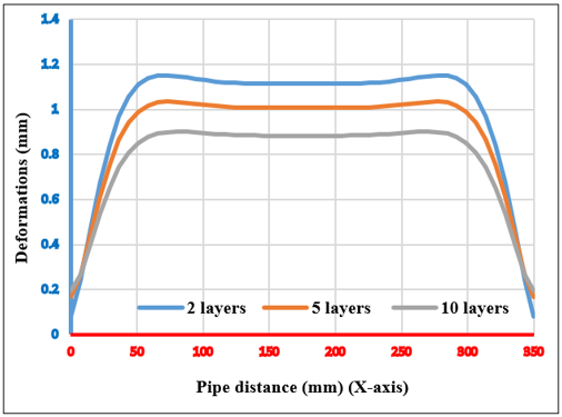
The outer diameter of the 10-layer pipe is the largest (80 mm), and bending stiffness and extensional stiffness are also the greatest, and stress flows are evenly distributed. The deformation is also decreased to 1.0537 mm. This is very favourable behaviour of a pressure vessel under the simulated conditions. The distribution of deformation in Figures 4 and 5 shows that there is no linear form of deformation reduction with the ply number. The authors explain that the contribution of each additional ply to stiffness depends on ply orientation: hoop-oriented plies add disproportionately to pressure resistance, and increased thickness adds geometric stiffness (a nonlinear D-matrix effect). In addition to the above, extreme deformation occurs at mid-length, and at the extremes, the effect of constraint is evident in radial expansion. As the layer count increases, the deformation pattern becomes smoother and more uniform. These data reveal local compliance Reduction and shear-coupling improvement, and improved structural continuity [26].
Figure 5 shows the nature of deformation in the pipe over a 350 mm length under an internal pressure of 20 MPa in the 2, 5, and 10-layer pipes. The statistics reveal that the greatest deformation occurs at the midpoint of the pipe, and the constraint effect is felt at the ends. The more layers one has, the smoother and more even the deformation profile is, and the higher the degree of structural continuity and the lower the local compliance. Moreover, the graph shows that the linear relationship between deformation and the number of plies does not hold [27].
Figure 5. Deformation profiles across the pipe length for varying layer counts
7.2 Stress distribution and edge effect trends
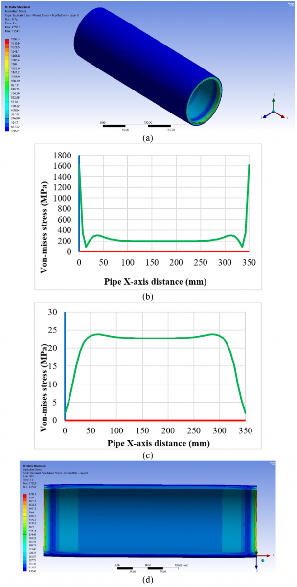
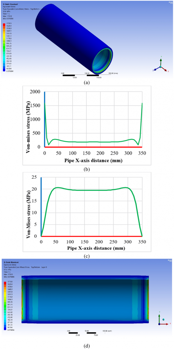
The structural response of a hybrid composite pipe is assessed, specifically the development of stresses in the 2-layer (0/45°) design under a constant internal load of 20 MPa in Figure 6(a)-(d). By combining ANSYS simulation data with CLT, the authors can determine how the absence of hoop-oriented plies affects overall mechanical efficiency and load-bearing capacity. The visualization, in terms of stress-distance profiles and stress-distance-equivalent stress 3D maps, provides a closer look at the load distribution between a high-modulus carbon/epoxy core and an outer polyethylene reinforcement. The results of this study highlight the critical role of boundary constraints and material anisotropy in affecting the structural integrity of the 350 mm pipe assembly [28].
Figure 6(a) shows the overall stress values and distributions over all the pipe, from the simulation result the stress constrain with high values at the edges and the inner side of the pipe, one of the most important remarks of the Figure 6(b) plot is the existence of severe stress spikes at extreme ends of the pipe (0 mm and 350 mm) wherein von Mises stress is calculated to be greater than 1600 MPa. The presence of these severe stress spikes is a direct consequence of the fixed and displacement supports in the professional ANSYS model, which replicate the real-world connections. A constrained edge is changed to a free-deforming body through a form of transition in composite mechanics, which introduces large interlaminar shear stresses and an edge effect. These boundary stresses indicate a high probability of localized first-ply failure at the connection points, since at the load limit, when the longitudinal tensile strength of the inner carbon/epoxy layer is limited to 1500 MPa, numerous sources of localized failure exist [29].
Figure 6. Stress values and distributions for the two-layer composite pipe system: (a) all composite pipe, (b) inner layer stress, (c) outer wall layer stress, and (d) section of inner stress
From a finite element point of view, it is important to note that the absolute values of these edge stresses (for example, >1600 MPa in the 2-layer model) are observed exactly at the fully constrained boundary nodes. These in-hand raw values are therefore highly sensitive to the known phenomenon of “locking” in FEA, or mathematical constraint singularities, when all degrees of freedom are locked at nodes, allowing no deformation in that area and leading to mathematically concentrated stresses. Hence, these raw maxima are not considered as absolute, physical, design-driven failure limits. Instead, they are very useful measures of comparison, relative to each other. As all models share the same mesh density, element formulation, and boundary conditions, the relative decrease in this singular peak (to 1350 MPa in the 10-layer model) provides a valid, quantifiable measure of the stacking sequence's efficiency. Shows the great ability of the quasi-isotropic shell to structurally redistribute extremely high interlaminar shear lag and boundary loads before the extreme constraint point is reached.
The large difference in stress magnitude between the two material regions, as shown by the simulation, is due to the laws of CLT. The inner carbon/epoxy core, whose Young's modulus reaches up to 150 GPa, supports the load and remains in a steady state at a medium stress level of about 200 MPa throughout the medium. Conversely, the stress in the outer polyethylene shell is significantly lower, at about 23 MPa, as shown in Figure 6(b). This is not surprising because it has a much lower modulus (8–12 GPa), is therefore more compliant, and cannot share the primary pressure load. This particular stacking sequence of pressure vessels can also be seen as structurally wasteful, as illustrated by the 2-layer design. Since this design lacks a 90° (circumferential) layer, it withstands hoop stress poorly, which is the most significant contributor to failure in cylindrical vessels. The 0°-layer provides axial rigidity, and the 45°-layer provides shear resistance; however, their combined failure to contain radial expansion results in the highest observed deformation of 1.2395 mm. These findings demonstrated a failure of the 2-layer model under uniformly distributed stress, which increased the model's compliance and led to a less stable hybrid shell system, as shown in Figure 6(c). The inner and outer stress plots show a horizontal region between 100 mm and 250 mm (see Figure 6(d), indicating that the pipe is in structural equilibrium at the affected ends. The distribution of stress in this area is controlled by internal pressure (P) and the thickness-to-radius ratio (t/r). The stress is constant across these points, but the physical deformation profile reaches its maximum at the midpoint. Even with stresses, it is clear that stresses are constant, but because the 2-layer model lacks ply-controlled geometric hardness, maximum outward bulging can occur at all these points [30].
The analysis focuses on the structural performance of a hybrid composite pipe with an outer wall composed of 5 layers (0/45/90/135/180), under an internal pressure of 20 MPa, as shown in Figure 7(a)-(d). The simulation shows a greater increase in hoop stiffness and a redistribution of loads with the proposed, more complex stacking sequence, which goes beyond a basic 2-layer configuration. These findings, obtained by analyzing stress-distance profiles and 3-D von Mises maps, make a scientific contribution to understanding how integrating a 90° reinforcement layer stabilizes the high-modulus carbon/epoxy core against radial expansion [31].
The simulated values for the 5-layer assembly shown in Figure 7(a) and (b) provide a close-up view of the mechanical enhancement resulting from increased ply count and diversified fiber orientation. As in the 2-layer case, the stress recorded in Figure 7(b) shows extreme spikes at the fixed and displacement supports of the pipe (0 mm and 350 mm). The von Mises stress is maximum at these boundaries, approximately 1580 MPa. The peak is very high, but slightly lower than the 1600+ MPa observed in the 2-layer model. Considering the longitudinal carbon/epoxy strength limit of 1500 MPa, the 5-layer setup exhibits a minor yet significant decrease in the intensity of localized edge-effect singularities. The major scientific transfer in this model is the possibility of introducing a 90° (circumferential) layer. The CLT indicates that a 90° layer provides direct resistance to the hoop stress, the major cause of radial deformation. This increases confinement by adding circumferential confinement, resulting in a total displacement of 1.1548 mm, a 7% improvement over the 2-layer setup [32].
Figure 7. Stress values and distributions for the five-layer composite pipe system: (a) all composite pipe, (b) inner layer stress, (c) outer wall layer stress, and (d) section of inner stress
This 5-layer sequence (0/45/90/135/180) aims to spread hoop and transverse resistance over 180° of orientation, resulting in a more uniform stress distribution. The stress ratio between the inner core and the outer shell remains high, and the high-modulus carbon/epoxy core can be considered the main load-carrying structure [33]. The stress in the mid-section is maintained at about 190–200 MPa in the inner core. Remarkably, the outer polyethylene shell, as shown in Figure 7(c), exhibits the highest stress of about 20.5 MPa, compared with 23 MPa in the 2-layer model. This means that the outer shell can better resist deformation, and the extra layers and the 90° orientations can be more effective in reducing the localized stress intensity. The horizontal plateau between 100 mm and 250 mm in the inner and outer stress plots, as shown in Figure 7(d), confirms the attainment of structural equilibrium at the unaffected ends. The geometric stiffness of the hybrid shell system increases with the addition of layers and a higher t/r ratio. The 5-layer design has a more hoop-reinforced load path, which is more stable and less structurally wasteful than the 2-layer design, which initially produces an anisotropic distortion [34].
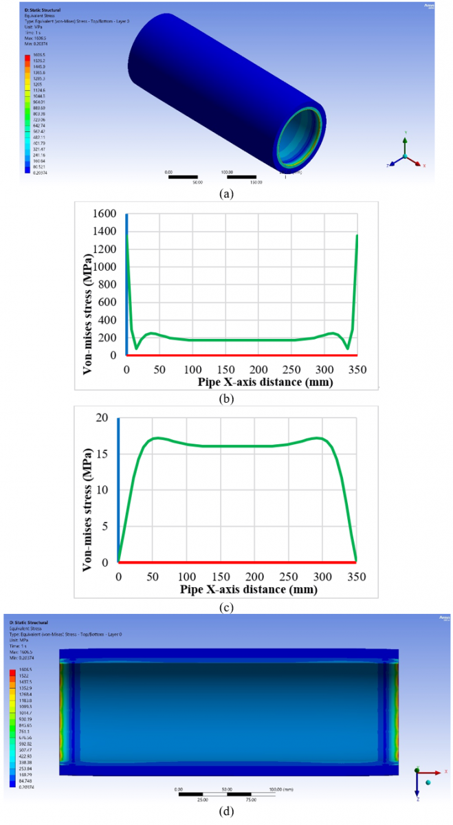
The analysis of Figure 8(a)-(d) determines the mechanical response of a hybrid composite pipe with an outer wall of 10 layers and a quasi-isotropic [0/45/90/135/180/225/270/315/0/0] orientation sequence, increasing by 45°, under a 20 MPa internal load. There is a buildup of both extensional and bending rigidities due to this tightly stacked sequence, and the simulation illustrates the transition to ideal pressure-vessel behavior, with high-quality load redistribution and low radial expansion. Such findings, developed using cutting-edge von Mises stress maps and surface profiles, would provide a scientific reference point for optimizing the structural continuity and reducing localized compliance in high-pressure hybrid assemblies.
The 10-layer structure demonstrated the most favourable response among the models examined, exhibiting quasi-isotropic behavior and a highly balanced mechanical state, as depicted in Figure 8(a). Figure 8(b) shows a further tendency toward extreme stress confinement at the fixed and displacement supports (0 mm and 350 mm). These boundaries have a maximum von Mises stress of about 1350 MPa. A significant difference to note is that the maximum stress at the pipe boundaries is 1350 MPa; this is not a physical strength limit of the material but rather a comparative performance metric. Although these values are relatively high due to high stress concentrations in the finite element model under fixed boundary conditions, they are used primarily as a guideline to assess structural efficiency. These decreased peak values across different stacking sequences can be used to quantify the effect of the 10-layer quasi-isotropic architecture on interlaminar shear and boundary loads, as opposed to the 2-layer baseline, though this is not meant to imply that the material is physically at a failure bound.
Figure 8. Stress values and distributions for the ten-layer composite pipe system: (a) all composite pipe, (b) inner layer stress, (c) outer wall layer stress, and (d) section of inner stress
This is a significant decrease compared to the 1600+ MPa observed in the 2-layer model and the 1580 MPa in the 5-layer model. Although such absolute peak values are not actual physical stresses, the 10-layer setup shows a deep cutback in the local stress concentration relative to these values. This means that the quasi-isotropic structure is highly effective at redistributing loads away from concentrated areas through rigid connections before reaching the point of extreme edge effects [35].
The 10-step cycle [0/45/90/135/180/225/270/315/0/0] leverages the pipe's internal resistance through a series of major processes. Such a setup maximizes extensional rigidity and greatly enhances bending rigidity, which scales with thickness cubed. The sequence will minimize coupling, helping maintain the pipeline straight and avoid anisotropic distortion under load. All these elements result in a minimum deformation of 1.0537 mm, which is 15% better than the basic 2-layer configuration. The interfacial stress between the core and shell indicates the high efficiency of the 10-layer reinforcement. A high level of core carbon/epoxy stabilizes the stress at about 170–180 MPa in the mid-section, which is lower than the 200 MPa observed in the thinner models. The pressure on the outer polyethylene shell, as illustrated in Figure 8(c), is highest at approximately 17.2 MPa at 250 mm. This has been recorded as a significant reduction compared to 23 MPa and 20.5 MPa for the 2- and 5-layer models, respectively. It establishes that as the number of layers is increased to 10, the outer shell can provide the highest level of circumferential confinement while still experiencing reduced localized stress intensity. The extensive horizontal plateau at 100–250 mm in the stress plots, as shown in Figure 8(d), indicates that the pipe attains a highly stable structural balance away from the affected ends. With an outer diameter of 80 mm, the model has the greatest geometric stiffness and the most stable load path, indicating excellent structural continuity and reduced local compliance. The more layers, the smoother and more uniform the deformation profile will be.
7.3 Composite pipe deformation and stress analysis results comparison
The analytical goal of this study is a comparative analysis and a quantified evaluation of the shift from a simple reinforcement strategy to a high-efficiency quasi-isotropic design, as illustrated in Table 7. This table enables precise determination of the effect of a particular change on the mechanical response of the hybrid pipe by summarizing the results of multiple ANSYS simulations, i.e., increasing the number of plies and varying their fiber orientations.
Table 7. Mechanical performance and stress-deformation comparison of 2, 5, and 10-layer hybrid composite pipes
|
Feature / Model |
2-Layer Model (0/45°) |
5-Layer Model (0–180°) |
10-Layer Model [0/45/90/135/180/225/270/315/0/0] |
|
Outer Wall Diameter |
71 mm |
75 mm |
80 mm |
|
Max. Total Deformation |
1.239 mm |
1.1548 mm |
1.053 mm |
|
Peak Inner Boundary Stress |
>1600 MPa |
1580 MPa |
1350 MPa |
|
Steady-State Core Stress |
200 MPa |
190–200 MPa |
170–180 MPa |
|
Max. Outer Shell Stress |
~ 23 MPa |
~ 20.5 MPa |
17.2 MPa |
|
Mechanical Efficiency |
Lowest; lacks hoop stiffness |
Improved; 7% less deformation |
Highest quasi-isotropic behavior |
The results in Table 7 demonstrate that deformation is reduced by 15% as the number of layers increases to 10, and that rigidity is maximized when both extensional and bending modes are used. The 10-layer design shows the highest capacity to resist trends in severe boundary stress concentration, allowing optimal continuity of structural layout and load transfer adjacent to stiff joints. The 90° reinforcement introduced in the 5- and 10-layer models is advantageous because it stiffens the internal core and enables a transition from the structurally inefficient axial construction to an efficient pressure vessel. The findings support CLT, providing empirical evidence that increasing the stiffness matrix accumulation is directly correlated with a decrease in radial expansion. It also shows that the decrease in deformation (7% to 8.7% per stage) is not linear, indicating that the value added by an additional layer and the extra cost are related to the degree of additional safety in high-pressure operations.
7.4 Vibration results under 20 MPa pressure analysis
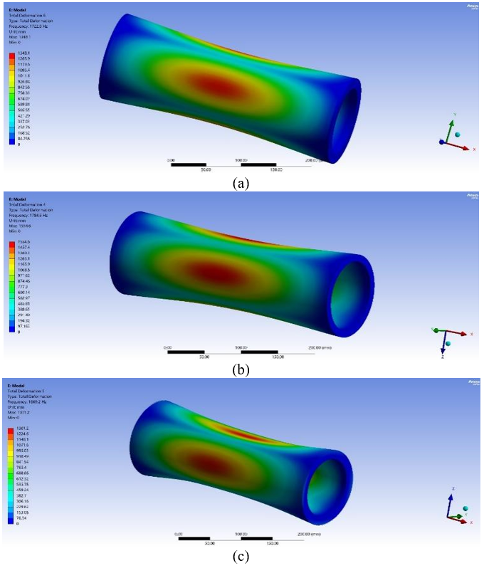
The analysis presented below, in Figure 9(a)-(c), compares the dynamic properties of three hybrid composite pipe designs (2, 5, and 10 layers) tested under a pre-stressed internal load of 20 MPa. By incorporating the stress-stiffness matrix of a stationary structural solution into the modal system, the research determines the effects of internal pressure and different stacking sequences on the pipe's natural vibration profile and modal stability. The structural continuity and vibration resistance of high-pressure hybrid assemblies are supported by these results, as visualized in 3D total deformation mode shapes. The modal analysis indicates that the number of plies added to the outer polyethylene wall and the decrease in maximum vibrational deformation are directly related. To accurately approximate the pipe's working conditions, the simulation employs a pre-stressed eigenvalue problem. This 20 MPa load condition is then introduced through the stress-stiffness matrix, which plays a major role in changes in the pipe's overall rigidity. Hence, the natural vibrations obtained may provide insight into the dynamic behavior under the simulated pre-stressed conditions [36].
The pre-stressed modal shapes for the composite cylinders, generated based on the associated mode numbers, are shown in Figure 9, which clearly illustrates the physical dynamic behavior of the composite cylinders subjected to an internal pressure of 20 MPa. The acceptable values for these displacements represent the relative amplitudes of the modes when the solver solves the exercise, because the modal eigenvectors are normalized for mass. The 2-layer model (Figure 9(a)) has no plies oriented in the hoop direction, making the localized oscillatory swing highly evident, as indicated by a mass-normalized modal amplitude of 1348.1. Switching to the 5-layer configuration (Figure 9(b)), the structure is more resistant to radial expansion, and the dynamic response changes, resulting in a peak normalized amplitude of 1554.6. However, the highest degree of dynamic equilibrium is shown by the 10-layer quasi-isotropic architecture (Figure 9(c)). Since its outer diameter is 80 mm, which provides high bending rigidity (D-matrix), the 10-layer model could successfully suppress localized instabilities and resulted in the lowest normalized modal amplitude of 1301.2. This uniform and symmetric form indicates that the continuous 0°–360° fiber distribution can effectively mitigate severe anisotropic coupling under high-frequency vibration. Table 8 presents a comparative analysis that provides a quantitative synthesis of the dynamic behaviour of the three hybrid pipe mechanisms studied in a prestressed state. This table compares peak and minimum deformation values from ANSYS modal simulations to demonstrate how the high-displacement instability of the basic reinforcement designs can be mitigated by the response-stabilized quasi-isotropic design [37].
Figure 9. Deformation values and distributions according to the vibration: (a) 2-layer composite pipe, (b) 5-layer composite pipe, and (c) 10-layer composite pipe
Table 8 presents a complete quantitative synthesis of the pre-stressed dynamic behavior of the three configurations, evaluated in terms of true natural frequencies rather than raw modal displacement. The stress-stiffness matrix of 20 MPa is quite stiff, and the first orthogonal shell ovalization modes are represented by the fundamental natural frequencies, which appear in pairs with identical numbers (Modes 1 and 2). For this particular geometry, the highest fundamental frequency is obtained in the 5-layer construction at 1382.3 Hz, thereby representing the optimal dynamic stiffness-to-mass ratio. The basic frequency recorded by the 10-layer model, on the other hand, is 1183.3 Hz. In the classical concept of structural dynamics, the slight decrease in frequency reflects that while the polyethylene shell, with the highest thickness (80 mm Do), adds considerable mass to the system, it increases the system's structural stiffness only marginally and consequently affects the stiffness-to-mass ratio. This added mass, however, is an extremely effective dynamic damper. The most dynamically stable assembly is the 10-layer quasi-isotropic assembly, with the minimum mass-normalized amplitude (1301.2). It has been proven to effectively dampen high-frequency vibrations, where “fast” is important, making it the top pick for industrial applications demanding vibration control under high pressure.
Table 8. Modal comparative performance and pre-stressed vibrational deformation benchmarks of hybrid composite pipes
|
Feature / Model |
2-Layer Model (0°/45°) |
|
Outer Diameter (Do) |
71 mm |
|
Max. Mass-Normalized Amplitude |
1348.1 |
|
1st natural frequency |
1209.4 |
|
2nd natural frequency |
1209.4 |
|
3rd natural frequency |
1628.2 |
|
Pre-Stress Load |
20 MPa |
|
Structural Stability |
Lowest; high local compliance |
As demonstrated in this paper, the increase in ply from 2 to 10 layers reduces radial deformation rate by 15% and results in a final displacement of 1.0537 mm. These findings are in line with those of Sulaiman et al. [15], who reported that enhancing burst pressure and shell stability by complexifying fiber orientation towards a balanced configuration significantly improves them. Although Júniora et al. [13] demonstrated the optimal stress balance at 55, the quasi-isotropic 10-layer sequence [0/45/90/135/180/225/270/315/0/0] in the present study achieves the same level of structural perfection by maximizing the extensional and bending stiffness matrices. It helps distribute the 20 MPa internal load across all planes. Similarly, as Ozbek [8] reported that fiber orientation varies with hybridization and stiffness, the observed results affirm that the introduction of 90 (hoop) plies in the 5- and 10-layer architectures is the main factor in radial confinement.
Behavior at the pipe supports is a crucial point for evaluating stress. The study observed extreme spikes of up to 1600 MPa in the 2-layer model, which decreased to approximately 1350 MPa in the 10-layer model. This effect can be compared to the so-called edge effect and shear lag theories presented by Stabla et al. [5], in which the change in support of a confined constrained body to a free-deforming one produces localized interlaminar shear stresses. The 10-layer structure confirms the progressive failure hypotheses of Alexander and Augustine [12], whereby Ply orientation is an important factor in achieving optimal load transfer at connection areas, as the magnitude of the boundary stress singularities can be considerably reduced. The modal analysis showed that the vibrational deformation was reduced by 3.5% in the 10-layer model. The trend is closely tied to the mathematical models presented by Yarashev et al. [4], who found that internal pressure is the final parameter used to define the stabilizing eigenfrequencies. A conclusion reached by Yarashev et al. [4] is the significant benefit of pre-stressing a pipe, which is confirmed by the current use of a stress-stiffness matrix to account for the 20 MPa load; another data set that confirms this is that oscillatory swings decrease significantly during the thickening of the shell to 80 mm.
The steady-state solution for the midsection of the pipe (X = 100–250 mm) was quantitatively and qualitatively compared with a classic theoretical baseline using Lamé's equations for thick-walled cylinders to validate the accuracy of the ANSYS numerical solver. The mid-section is the only area where the radial/shear (hoop) equilibrium is pure (zero interlaminar shear/bending), allowing a 2D analytical check at that location due to the fixed boundaries. Due to a very large difference in stiffness between the carbon/epoxy core (Ei = 130 GPa) and the polyethylene shell (E = 10 GPa), the theoretical baseline is that the whole of the internal pressure (20 MPa) is taken up by the 5 mm thickness of the core (inner = 32.5 mm and outer = 37.5 mm). According to Lamé's solution, the maximum theoretical hoop stress at the inner wall is equal to:
$\sigma_{h=} P\left\lceil\frac{\left(r_0^2+r_i^2\right)}{\left(r_0^2-r_i^2\right)}\right\rceil$
Then, the theoretical hoop stress at the inner wall is 140.7 MPa as the baseline. This same region shows a steady-state von Mises core stress of ~170 MPa in the ANSYS 10-layer model. This provides a very good quantitative correlation. The deviation is naturally expected at the mathematical level, since the analytical Lamé baseline does not account for 3D orthotropic coupling (or B-matrix), Poisson's volumetric expansion, and longitudinal bending moments, which are implemented in the high-fidelity ANSYS solver. Hence, this theoretical benchmark validates the FEA solver's basic operations before adding the complex boundary singularities.
Through the extensive numerical analysis on the hybrid composite pipes (carbon and epoxy or polyethylene) under 20 MPa internal pressure, the following concrete design rules and structural conclusions are presented:
In summary, it is structurally insufficient to use simple layup starting conditions for severe loading. With 10 layers, the quasi-isotropic hybrid assembly provides the baseline level of engineering performance for high-pressure industrial applications, with a high-axial-stiffness core complemented by optimal circumferential confinement from the shell. The 20 MPa loading. That is, it forms a stress-stiffness matrix that increases the pipe's resistance to dynamic loading. The quasi-isotropic hybrid assembly with 10 layers demonstrated the highest stability and efficiency among the tested configurations for simulated high-pressure work. It combines high axial rigidity from the carbon/epoxy core with better circumferential confinement from the polyethylene shell, forming a strong, structurally continuous system that withstands both static and dynamic loads.
From the results of this study, it should be emphasized that a thin-walled construction or the use of simple cross-ply construction for structural integrity is not sufficient to safely handle high local stress concentrations arising from the boundaries of 20 MPa offshore and high-pressure industrial vessels. To ensure operational safety and avoid connection-point vulnerabilities, using a 10-layer quasi-isotropic hybrid configuration may provide crucial design guidance for industrial safety, rather than merely serving as an optimization step. From these results, it is recommended that high-pressure hybrid composite pipes can be manufactured and used in industries with the following:
For the hybrid category, the optimal outer diameter to target in the E. Shell Geometry Optimization is 80 mm, because the geometric and bending stiffnesses (D-matrix) will increase afterwards; thus, the deformation shape will be balanced, leading to consistent load transfer.
[1] Ilinca, C.N., Ramadan, I.N., Doukeh, R., et al. (2026). Experimental assessment of stress–strain response in filament-wound GFRP pipes under internal pressure loading. Materials, 19(3): 639. https://doi.org/10.3390/ma19030639
[2] Toh, W., Tan, L.B., Tse, K.M., et al. (2018). Material characterization of filament-wound composite pipes. Composite Structures, 206: 474-483. https://doi.org/10.1016/j.compstruct.2018.08.049
[3] Yin, D. (2024). A prediction approach for partial properties of filament wound composite tube considering fiber winding prestressing. Journal of Physics: Conference Series, 2891(15): 152016. https://doi.org/10.1088/1742-6596/2891/15/152016
[4] Yarashev, J.A., Safarov, I., Teshaev, M. (2021). Vibrations of multilayer composite viscoelastic curved pipe under internal pressure. IOP Conference Series: Materials Science and Engineering, 1030: 012073. https://doi.org/10.1088/1757-899X/1030/1/012073
[5] Stabla, P., Smolnicki, M., Błażejewski, W. (2021). The numerical approach to mosaic patterns in filament-wound composite pipes. Applied Composite Materials, 28(1): 181-199. https://doi.org/10.1007/s10443-020-09861-z
[6] Ouarhim, W., Zari, N., Bouhfid, R., El Kacem Qaiss, A. (2019). Mechanical performance of natural fibers-based thermosetting composites. In Mechanical and Physical Testing of Biocomposites, Fibre-Reinforced Composites and Hybrid Composites, pp. 43-60. https://doi.org/10.1016/B978-0-08-102292-4.00003-5
[7] Huang, Z., Qian, X., Su, Z., Pham, D.C., Sridhar, N. (2020). Experimental investigation and damage simulation of large-scaled filament wound composite pipes. Composites Part B: Engineering, 184: 107639. https://doi.org/10.1016/j.compositesb.2019.107639
[8] Ozbek, O. (2019). Determination of mechanical behaviors of filament wound hybrid composite pipes. Ph.D. thesis. Gaziantep University. https://www.researchgate.net/profile/Oezkan_Oezbek2/publication/337102253_DETERMIN.
[9] Guz, I.A., Menshykova, M., Paik, J.K. (2017). Thick-walled composite tubes for offshore applications: An example of stress and failure analysis for filament-wound multi-layered pipes. Ships and Offshore Structures, 12(3): 304-322. https://doi.org/10.1080/17445302.2015.1067019
[10] Ha, S.K., Khalid, H.R., Park, S.M., Lee, H.K. (2015). Interfacial crack-induced debonding behavior of sprayed FRP laminate bonded to RC beams. Composite Structures, 128: 176-187. https://doi.org/10.1016/j.compstruct.2015.03.040
[11] Jiang, B.H., Li, Z.B., Lu, F.Y. (2015). Failure mechanism of sandwich beams subjected to three-point bending. Composite Structures, 133: 739-745. https://doi.org/10.1016/j.compstruct.2015.07.056
[12] Alexander, A., Augustine, B.S.M. (2015). Stress analysis and progressive failure analysis of multilayered basalt/epoxy composites. Applied Mechanics and Materials, 766-767: 21-26. https://doi.org/10.4028/www.scientific.net/AMM.766-767.21
[13] Júniora, J.A., Tonattoa, M.L.P., Fariab, H., Marquesc, A.T., Amicoa, S.C. (2014). Effect of environmental conditioning on burst pressure of carbon/epoxy filament wound composite pipes. In ECCM16–16th European Conference on Composite Materials, pp. 22-26.
[14] Madhavi, M., Venkat, R. (2014). Predicting structural behavior of filament wound composite pressure vessel using three dimensional shell analysis. Journal of the Institution of Engineers (India): Series C, 95(1): 41-50. https://doi.org/10.1007/s40032-014-0094-4
[15] Sulaiman, S., Borazjani, S., Tang, S.H. (2013). Finite element analysis of filament-wound composite pressure vessel under internal pressure. IOP Conference Series: Materials Science and Engineering, 50(1): 012061. https://doi.org/10.1088/1757-899X/50/1/012061
[16] Teijeiro, T., Behnoudfar, P., Taylor, J.M., Pardo, D., Calo, V.M. (2025). Efficient numerical integration for finite element trunk spaces in 2D and 3D using machine learning: A new optimisation paradigm to construct application-specific quadrature rules. Journal of Computational Physics, 549: 114634. https://doi.org/10.1016/j.jcp.2025.114634
[17] Odeh, A., Al-Shugaa, M.A., Al-Gahtani, H.J., Mukhtar, F. (2024). Analysis of laminated composite plates: A comprehensive bibliometric review. Buildings, 14(6): 1574. https://doi.org/10.3390/buildings14061574
[18] Lyu, Y.T., Hung, T.P., Ay, H., Tsai, H.A., Chiang, Y.C., Lin, A.D. (2022). Derivation and verification of laminated composite T-beam theory. Applied Sciences, 12(21): 11158. https://doi.org/10.3390/app122111158
[19] Sohn, J.M., Hirdaris, S., Romanoff, J., Kim, S.J. (2022). Development of numerical modelling techniques for composite cylindrical structures under external pressure. Journal of Marine Science and Engineering, 10(4): 466. https://doi.org/10.3390/jmse10040466
[20] Karim, M.A., Abdullah, M.Z., Deifalla, A.F., Azab, M., Waqar, A. (2023). An assessment of the processing parameters and application of fibre-reinforced polymers (FRPs) in the petroleum and natural gas industries: A review. Results in Engineering, 18: 101091. https://doi.org/10.1016/j.rineng.2023.101091
[21] Wijewickrama, L., Jeewantha, J., Perera, G.I.P., Alajarmeh, O., Epaarachchi, J. (2025). Fiber-reinforced composites used in the manufacture of marine decks: A review. Polymers, 17(17): 2345. https://doi.org/10.3390/polym17172345
[22] Tefera, G., Adali, S., Bright, G. (2022). Mechanical behavior of GFRP laminates exposed to thermal and moist environmental conditions: Experimental and model assessment. Polymers, 14(8): 1523. https://doi.org/10.3390/polym14081523
[23] Kennedy, S.M., Robert, R.J., Prince, R.M.R., Hikku, G.S., Kaliraj, M. (2024). A comprehensive overview of the fabrication and testing methods of FRP composite pipes. MethodsX, 13: 102990. https://doi.org/10.1016/j.mex.2024.102990
[24] Alam, M.I., Maraz, K.M., Khan, R.A. (2022). A review on the application of high-performance fiber-reinforced polymer composite materials. GSC Advanced Research and Reviews, 10(2): 20-36. https://doi.org/10.30574/gscarr.2022.10.2.0036
[25] Rajak, D.K., Wagh, P.H., Linul, E. (2021). Manufacturing technologies of carbon/glass fiber-reinforced polymer composites and their properties: A review. Polymers, 13(21): 3721. https://doi.org/10.3390/polym13213721
[26] Ajayi, N.E., Rusnakova, S., Ajayi, A.E., Ogunleye, R.O., Agu, S.O., Amenaghawon, A.N. (2025). A comprehensive review of natural fiber reinforced polymer composites as emerging materials for sustainable applications. Applied Materials Today, 43: 102666. https://doi.org/10.1016/j.apmt.2025.102666
[27] Lukacs, J., Koncsik, Z., Chovan, P. (2022). Integrity increasing of damaged transporting pipelines using fiber reinforced polymer composite wrap systems. Engineering Failure Analysis, 137: 106284. https://doi.org/10.1016/j.engfailanal.2022.106284
[28] Diniță, A., Ripeanu, R.G., Ilinca, C.N., et al. (2023). Advancements in fiber-reinforced polymer composites: A comprehensive analysis. Polymers, 16(1): 2. https://doi.org/10.3390/polym16010002
[29] Gfrerrer, M., Koss, V., Wiener, J., Schuecker, C., Brunner, A.J., Pinter, G. (2025). Comparing mode I, mode II and mixed-mode I/II interlaminar fracture toughness of glass and carbon fiber reinforced polymer laminates with the same epoxy matrix system. Engineering Fracture Mechanics, 320: 111009. https://doi.org/10.1016/j.engfracmech.2025.111009
[30] Sam-Daliri, O., Jiang, Y., Flatharta, D., et al. (2025). Mechanical analysis of unidirectional glass fibre reinforced epoxy composite joints manufactured by adhesive bonding and co-curing techniques. Materials & Design, 258: 114739. https://doi.org/10.1016/j.matdes.2025.114739
[31] Sebeay, T.A., Ahmed, A. (2023). Numerical investigation into GFRP composite pipes under hydrostatic internal pressure. Polymers, 15(5): 1110. https://doi.org/10.3390/polym15051110
[32] Birleanu, C., Udroiu, R., Cioaza, M., Pustan, M., Paul, B., Vilau, C. (2025). The effect of fiber weight fraction on tribological behavior for glass fiber reinforced polymer. Polymers, 17(6): 720. https://doi.org/10.3390/polym17060720
[33] Saghir, F., Gohery, S., Mozafari, F.A.R.Z.I.N., et al. (2021). Mechanical characterization of particulated FRP composite pipes: A comprehensive experimental study. Polymer Testing, 93: 107001. https://doi.org/10.1016/j.polymertesting.2020.107001
[34] Srebrenkoska, S., Kochoski, F., Srebrenkoska, V., Risteska, S., Kotynia, R. (2023). Effect of process parameters on thermal and mechanical properties of filament wound polymer-based composite pipes. Polymers, 15(13): 2829. https://doi.org/10.3390/polym15132829
[35] Alsuhaibani, E., Aldukail, A. (2025). Experimental study on hybrid steel–GFRP reinforced concrete beams with different stirrup types and spacings. Buildings, 15(22): 4047. https://doi.org/10.3390/buildings15224047
[36] Mehra, A.S., Singh, S.B., Kodur, V. (2025). Structural behavior and failure characteristics of fiber-reinforced polymer-concrete composite beams incorporating glass roving tied GFRP shear connectors. Polymers, 17(23): 3201. https://doi.org/10.3390/polym17233201
[37] Takayanagi, H., Xia, M., Kemmochi, K. (2002). Stiffness and strength of filament-wound fiber-reinforced composite pipes under internal pressure. Advanced Composite Materials, 11(2): 137-149. https://doi.org/10.1163/156855102760410333