Hussein K. Halwas* | Abdulkareem Abdulwahab | Sami Muhsen
© 2026 The authors. This article is published by IIETA and is licensed under the CC BY 4.0 license (http://creativecommons.org/licenses/by/4.0/).
OPEN ACCESS
This research presents a thermodynamic evaluation of a combined cycle power plant (CCPP) with emphasis on optimizing the Heat Recovery Steam Generator (HRSG). The analysis investigates how pinch-point and approach-point temperature differences influence heat recovery and overall cycle efficiency. The results were positive, with a greater total thermal efficiency. Findings show that increasing the turbine inlet temperature enhances the total thermal efficiency, reaching up to 63% for the combined cycle compared to 46% for the gas turbine alone. The findings also indicate that higher ambient air temperatures (AATs) raise the exhaust gas temperature, enabling up to 12–15% more steam generation under elevated conditions. Furthermore, a lower pinch-point difference improves heat transfer but requires larger exchanger surfaces. Overall, the optimized HRSG configuration increases superheated steam production and improves thermal performance of the CCPP.
combined cycle power plant, gas turbine, steam turbine, Heat Recovery Steam Generator, thermodynamics analysis
Combined cycle power plants (CCPPs) integrate a gas turbine (GT) and a steam turbine (ST), using a Heat Recovery Steam Generator (HRSG), which is a key component of modern, highly efficient power systems. In such plants, the gas turbine operates on the Brayton cycle, and its exhaust heat is recovered by the HRSG to produce the steam required by the steam turbine, which in turn operates on the Rankine cycle. Thus, the term "combined cycle" reflects the integration of these two thermodynamic processes [1-3]. In a standard combined cycle power plant, the hot exhaust gases from the gas turbine flow directly into the HRSG, where they produce superheated steam at the required pressure and temperature without the need for additional fuel. Fuel consumption is thus limited to the gas turbine's combustion chamber. Because the HRSG provides the thermal link between the GT and the ST, its design is critical to maximizing heat transfer and improving overall plant efficiency. An efficient HRSG design aims to optimize heat exchange while minimizing surface area, taking into account factors such as the heat transfer coefficients of the working fluids in the economizer and evaporator sections, relative to the temperature and flow rate of the gas turbine exhaust. An open cycle gas turbine consists of a compressor, a combustion chamber, and a turbine. The compressor compresses the air before it is mixed with fuel in the combustion chamber. The resulting high-temperature gases, typically between 900 and 1400 ℃, expand through the turbine to generate power, releasing flue gas [4]. Flue gas refers to the combustion products that exit through a chimney or duct, usually from boilers, furnaces, or other power generation equipment.
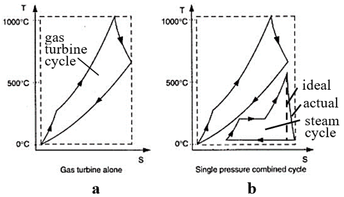
The combined cycle power plant concept is based on two fundamental thermodynamic cycles: the gas turbine cycle (Brighton) and the steam turbine cycle (Rankine), as illustrated in Figure 1 [5]. From this figure, the input temperature in a gas turbine cycle is much higher than the input temperature in a steam cycle.
Figure 1. Gas-steam combined cycle. (a) Gas turbine cycle having excessive waste heat, (b) combined cycle using turbine exhaust to produce steam efficiently
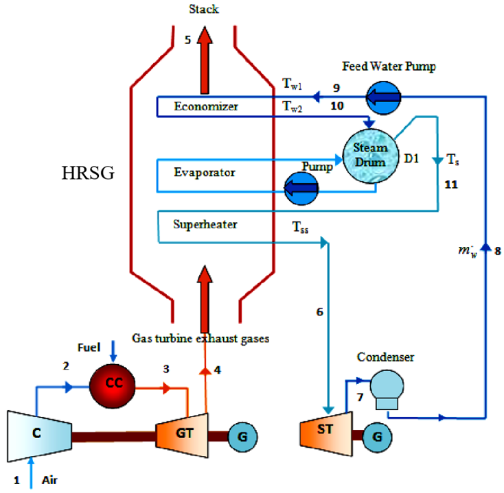
As we stated earlier, the combined cycle integrates two thermodynamic processes: the Brayton cycle (gas turbine) and the Rankine cycle (steam turbine). High temperature flue gases from the gas turbine enter the HRSG, where they transfer heat to the water and generate steam, most of the required energy being the latent heat of vaporization. In the gas turbine, compressed air mixes with fuel and combusts at high temperature, driving the turbine and producing electricity. In a combined cycle plant, the waste heat from the gas turbine is recovered rather than discharged, improving overall efficiency. The HRSG captures this exhaust heat to produce steam for the steam turbine, which drives an additional generator and increases total power output, as shown in Figure 2.
Figure 2. Schematic of a simple combined cycle power plant [6]
This design is more advanced than the simpler design shown in Figure 2, as it incorporates key thermodynamic components such as a superheater (SH), reheater (RH), condenser, and feedwater heaters, including a deaerator. Without additional heating, the steam exiting the drum remains saturated and condenses quickly; therefore, recovering its latent heat significantly improves thermal efficiency [6]. However, excessive condensation can pose a problem for turbine operation, as typical guidelines specify a moisture content of 10% in the downstream stages of a low pressure (LP) turbine [7]. The moisturize levels exceeding this limit can cause significant blade erosion and damage. Since the advent of steam generators, designers have been constantly improving the condenser, the main heat exchanger (HE) in the system, as thermodynamic analysis shows that efficient steam condensation can increase turbine output by about one-third [8]. As steam condenses in the condenser, a strong vacuum is generated, increasing the thrust through the LP turbine. However, heat loss due to waterside fouling, scaling, or steam air in-leakage can significantly reduce efficiency, potentially costing the plant five to six figure increases in annual fuel expenses [9]. The steam surface condenser is a central component of thermal power plants and a critical element of the water-steam cycle. Its performance directly affects the plant's power output, operating costs, and overall efficiency. Because condenser heat transfer governs the final stage of steam energy extraction, maintaining high heat exchange efficiency is essential for optimal plant performance [10]. Deficiencies in the condenser can arise from multiple sources, leading to reduced power output, increased fuel consumption and operating costs, poor environmental performance due to high carbon dioxide emissions, and ultimately reduced profit margins [11]. The performance of the condenser in a steam turbine system depends primarily on the effectiveness of heat transfer from the exhaust steam to the cooling water; the faster the heat removal rate, the faster the steam condenses. While many power plants have focused on improving heat consumption rates through combustion optimization, furnace adjustment, fuel modification, and turbine upgrades [12-14], the performance of the condenser and its influence on overall cycle efficiency has received comparatively less attention. This study addresses this gap by conducting a detailed thermodynamic analysis of a single pressure, unfired HRSG integrated into a CCPP. Unlike previous studies that have examined CCPP performance using simplified assumptions, this work provides a focused evaluation of HRSG heat transfer behavior through pinch point and approach point temperature analysis. The study quantifies the effects of turbine inlet temperature, exhaust gas temperature, and ambient air temperature (AAT) on heat recovery and combined cycle efficiency, and develops thermal balance relationships to determine optimal operating conditions that maximize steam generation and cycle performance. The findings offer a clearer understanding of how HRSG design parameters influence overall CCPP efficiency and provide practical guidance for enhancing heat transfer effectiveness in real power plant applications.
2.1 Heat transfer in Heat Recovery Steam Generator design
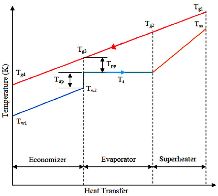
One of the most noticeable distinctions in HRSG design and operation are the different waterwall tube and superheat/reheat panels (also known as harps) that are arranged in portions along the flue gas steam. Figure 3 depicts the heat transfer between the flue gases that exit the gas turbine and the water that enters the turbine (HRSG). The lower line explains the water-to-steam process, in which evaporation occurs at a constant temperature and superheated steam occurs at a superheated temperature. The region between the exhaust and water profiles represents the heat loss in the HRSG. The pinch point temperature differential (∆Tpp) is an important design parameter [15]. Heat balances in the HRSG are used to determine several metrics important for assessing the combined cycle.
The pinch point temperature difference (∆Tpp) is the difference in temperature between the evaporator exhaust temperature (Tg3) and the temperature of water evaporation (Ts), as provided in Eq. (1). Water evaporation occurs at a constant temperature (isothermal operation) and at a constant pressure in the cylinder. The temperature difference at the scratch point is between 5 ℃ and 15 ℃. When the scratch point at a temperature differential is lower, the cost at the HE is higher [16]. A temperature cross is thermodynamically impossible in the economizer and evaporator parts of a HE gas [15]. If a design assumes a stack temperature for its calculations without checking the zero point of temperature difference, a temperature cross situation can occur. Furthermore, it is critical for all HRSG designers to base their calculations on the scratch point temperature differential rather than the stack temperature. In this scenario, we can structure the composite curves by combining hot and cold curves that have been pushed horizontally toward each other [17]. The gas departing the HRSG heats the feedwater entering the economizer to a temperature near the saturation temperature of steam at the unit's working pressure. The approach temperature (Tap) is the difference between the saturation temperature (Ts) and the economizer outlet temperature (Tw2) as provided in Eq. (2):
$\mathrm{T}_{\mathrm{pp}}=\mathrm{T}_{\mathrm{g} 3}-\mathrm{T}_{\mathrm{s}}$ (1)
$\mathrm{T}_{\mathrm{ap}}=\mathrm{T}_{\mathrm{s}}-\mathrm{T}_{\mathrm{w} 2}$ (2)
Heat transfer is influenced by the mass flow of hot gases, the mass flow of water or steam, the temperature difference, and the surface area. To a certain extent, a single-pressure HRSG can recover heat.
Figure 3. Heat transfer diagram of a simple Heat Recovery Steam Generator (HRSG) with counterflow exhaust gas and water/steam
2.2 Heat balances in Heat Recovery Steam Generator design
The energy balance of each section in HRSGs can be examined using the pinch point temperature of the exhaust and flue gases of the heat recovered, which refers to Eqs. (3) and (4):
$\mathrm{Q}=\mathrm{m}_{\mathrm{gt}} \mathrm{C}_{\mathrm{pg}}\left(\mathrm{T}_{\mathrm{g} 1}-\mathrm{T}_{\mathrm{g} 4}\right)$ (3)
$\mathrm{Q}=\mathrm{m}_{\mathrm{st}}\left(\mathrm{h}_{\mathrm{sh}}-\mathrm{h}_{\mathrm{fw}}\right)$ (4)
where, $\mathrm{m}_{\mathrm{gt}}$ denotes the mass flow rate of exhaust gases through the gas turbine, and $\mathrm{m}_{\mathrm{st}}$ is the mass flow rate of steam generation, while $\mathrm{C}_{\mathrm{pg}}$ represents the specific heat of the flue gases, as seen in Eq. (5):
$\begin{gathered}\mathrm{C}_{\mathrm{pg}}=1.8083-2.3127 * 10^{-3} \mathrm{~T}+4.045 * 10^{-6} \mathrm{~T}^2 -1.7363 * 10^{-9} \mathrm{~T}^3\end{gathered}$ (5)
Heat balances in an economizer are defined as Eq. (6):
$\mathrm{m}_{\mathrm{gt}} \mathrm{C}_{\mathrm{pg}}\left(\mathrm{T}_{\mathrm{g} 3}-\mathrm{T}_{\mathrm{g} 4}\right)=\mathrm{m}_{\mathrm{st}}\left(\mathrm{h}_{\mathrm{s} 1}-\mathrm{h}_{\mathrm{fw}}\right)$ (6)
where, $\mathrm{h}_{\mathrm{s} 1}$ and $\mathrm{h}_{\mathrm{fw}}$ are the enthalpies of hot water in an economizer. While $\mathrm{T}_{\mathrm{g} 4}$ is the stack temperature of flue gases exiting the HRSGs. Eq. (7) defines the heat balances in an evaporator:
$\mathrm{m}_{\mathrm{gt}} \mathrm{C}_{\mathrm{pg}}\left(\mathrm{T}_{\mathrm{g} 2}-\mathrm{T}_{\mathrm{g} 3}\right)=\mathrm{m}_{\mathrm{st}}\left(\mathrm{h}_{\mathrm{s} 2}-\mathrm{h}_{\mathrm{s} 1}\right)$ (7)
where, $\mathrm{h}_{\mathrm{s} 2}$ is the enthalpy of the saturated water and $\mathrm{h}_{\mathrm{s} 1}$ is for steam. As for $\mathrm{T}_{\mathrm{g} 2}$ and $\mathrm{T}_{\mathrm{g} 3}$ represents the temperature of the gas at the inlet and outlet in the evaporator, respectively. The heat balancing equation is presented in the SH as shown in Eq. (8):
$\mathrm{m}_{\mathrm{gt}} \mathrm{C}_{\mathrm{pg}}\left(\mathrm{T}_{\mathrm{g} 1}-\mathrm{T}_{\mathrm{g} 2}\right)=\mathrm{m}_{\mathrm{st}}\left(\mathrm{h}_{\mathrm{sh}}-\mathrm{h}_{\mathrm{s} 2}\right)$ (8)
where, $\mathrm{h}_{\mathrm{sh}}$ is the enthalpy of the superheated steam and $\mathrm{T}_{\mathrm{g} 1}$ is the temperature of hot flue gas, inserting the HRSG design. By assuming the following temperature parameters as shown in Figure 3:
$\begin{gathered}\mathrm{T}_{\mathrm{g} 1}=5000^{\circ} \mathrm{C}, \mathrm{T}_{\mathrm{g} 2}=4000^{\circ} \mathrm{C}, \mathrm{T}_{\mathrm{g} 3}=230^{\circ} \mathrm{C}, \\ \mathrm{T}_{\mathrm{g} 4}=2000^{\circ} \mathrm{C}, \mathrm{T}_{\mathrm{ss}}=400^{\circ} \mathrm{C}, \mathrm{T}_{\mathrm{s}}=220^{\circ} \mathrm{C}, \mathrm{T}_{\mathrm{w} 2}=210^{\circ} \mathrm{C}, \\ \mathrm{T}_{\mathrm{w} 1}=110^{\circ} \mathrm{C}\end{gathered}$
The pinch point temperature (Tpp) and approach point differential (Tap) are calculated as follows:
$\begin{gathered}\mathrm{T}_{\mathrm{pp}}=\mathrm{T}_{\mathrm{g} 3}-\mathrm{T}_{\mathrm{s}}=10^{\circ} \mathrm{C} \\ \mathrm{T}_{\mathrm{ap}}=\mathrm{T}_{\mathrm{s}}-\mathrm{T}_{\mathrm{w} 2}=10^{\circ} \mathrm{C}\end{gathered}$
These two temperature differences are critical in HRSG design modeling. The pinch point is the smallest temperature difference between hot and cold streams. In HRSG, the hot streams are flue gases and the cold streams are water/steam. The effectiveness of heat transmission increases as the minimum temperature difference reduces, but so does the price of the HE. The difference between the temperature of water at the economizer exit and that of saturation at the evaporator drum pressure is the approach point. Temperature differences are taken into account to avoid early evaporation in the economizer tubes. Data and parameters for numerically modeling the gas turbine cycle are provided in Table 1.
Table 1. Technical specifications of gas turbine power plant (Brayton cycle)
|
Parameters |
Value |
|
Power of gas turbine |
29 MW |
|
Temperature of inlet air to compressor |
27 ℃ |
|
Pressure of inlet air to compressor |
100 Kpa |
|
Pressure of output air from compressor |
1000 Kpa |
|
Temperature of output air from compressor |
300 ℃ |
|
Temperature of hot gas inlet to gas turbine |
950 ℃ |
|
Temperature of hot gas inlet to HRSG |
500 ℃ |
|
Efficiency of compressor |
84% |
|
Efficiency of gas turbine |
88% |
The power of the Brayton Cycle is calibrated to maintain a constant power of 29 MW. The pressure ratio and temperature of the air intake rate to the compressor were calibrated to achieve 100 kPa and 27 ℃, respectively. While the increase in air outlet pressure ratio was set to 1000 kPa. The temperature of the air exiting from the compressor was kept at 300 ℃. The performance of the Brayton Cycle is investigated for altering the air inlet temperature, with compressor and gas turbine efficiencies of 84 and 88 percent, respectively. HRSG optimizes superheated steam output conditions based on the steam turbine's maximum permitted temperature and pressure ranges. The optimization criterion is to keep the temperature of superheated steam below the steam turbine's maximum permissible temperature limit. The design circumstances and requirements are used to build a steam turbine. Table 2 displays the steam turbine's parameters.
Table 2. Technical specifications of steam turbine power plant (Rankine cycle)
|
Parameters |
Value |
|
Power of steam turbine |
16 MW |
|
Power of combined cycle |
45 MW |
|
Pressure of steam at input of steam turbine |
10 Mpa |
|
Pressure of condenser |
8 Kpa |
|
Pressure of water at input of pump |
8 Kpa |
|
Pressure of output air from compressor |
1000 Kpa |
|
Temperature of steam at input of steam turbine |
40 ℃ |
|
Temperature of hot gas outlet from HRSG |
210 ℃ |
|
Efficiency of gas turbine |
90% |
|
Efficiency of pump |
80% |
|
Thermal efficiency of combined cycle |
63% |
|
Thermal efficiency of gas turbine |
46% |
This section presents the thermodynamic behavior of the CCPP under different operating conditions, with emphasis on the influence of pinch point temperature, exhaust gas temperature, turbine inlet temperature, and AAT. The discussion focuses on why these variations occur based on cycle thermodynamics and heat transfer principles. The heat recovered from the flue gases can be balanced in two ways: from the exhaust side and from the water profile. The heat recovery system from the gas turbine is computed using Eq. (9), and the heat recovery system from the steam turbine is calculated using Eq. (10):
$\mathrm{Q}_{\text {recovery}}=\mathrm{m}_{\mathrm{gt}} \mathrm{C}_{\mathrm{pg}}\left(\mathrm{T}_{\mathrm{g} 1}-\mathrm{T}_{\mathrm{g} 4}\right)$ (9)
$\mathrm{Q}_{\text {recovery}}=\mathrm{m}_{\mathrm{st}}\left(\mathrm{h}_{\mathrm{sh}}-\mathrm{h}_{\mathrm{fw}}\right)$ (10)
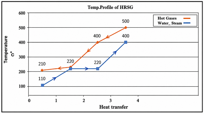
Figure 4 depicts the temperature enthalpy profile of the HRSG that was executed based on temperature parameters as provided in Section 2.2. This figure illustrates heat transfer between the hot flue gases and the water steam path. The profile highlights the locations of the economizer, evaporator, and superheater and emphasizes the minimum temperature difference (pinch point) in the evaporator section. The shape of the curves demonstrates that the evaporator operates near the saturation temperature, where heat addition is dominated by latent heat. Because phase change occurs at nearly constant temperature, the driving temperature difference between the two streams becomes small. This explains why the pinch point typically appears in the evaporator rather than in the economizer or superheater.
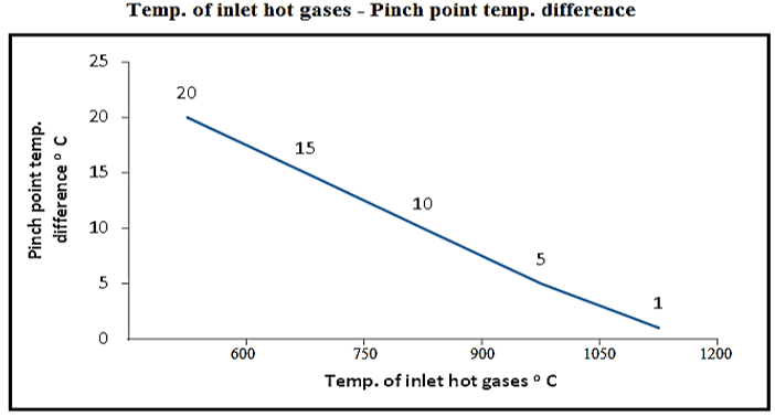
The relationship between the temperature of hot gases and the pinch point temperature difference (Tpp) in the HRSG is depicted in Figure 5. The pinch point temperature difference is a crucial distinction that must be considered [18], which is the difference between the saturation temperature and the temperature of the gas at the evaporator exit. Based on observations, the values of Tpp grow as the temperature of hot gases rises. This occurs because higher flue gas temperatures increase the temperature gradient between the evaporator exit and the steam saturation line. Consequently, more heat is available for recovery, but the increasing temperature difference also indicates that additional surface area would be required to maintain effective heat transfer in practical HRSG designs. A higher pinch point temperature difference generally reduces HE effectiveness. Therefore, while high exhaust temperatures supply more recoverable energy, they must be balanced with an economically feasible heat transfer area.
Figure 4. The temperature enthalpy (T-S) profile in the Heat Recovery Steam Generator (HRSG)
Figure 5. The temperature of inlet hot gases over pinch point temperature difference
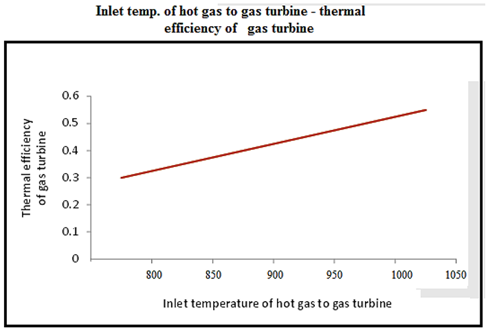
As illustrated in Figure 6, the thermal efficiency of a gas turbine increases as the temperature of hot gas rises. This trend follows the Brayton cycle principle: increasing the turbine inlet temperature raises the specific work output because the expansion ratio increases. With a larger temperature difference between the turbine inlet and outlet, more useful work is extracted per unit of fuel. Thus, increasing turbine inlet temperature directly improves the thermal efficiency of the topping cycle, which subsequently raises the amount of heat delivered to the HRSG and enhances steam production in the bottoming cycle.
Figure 7 illustrates the variation of heat supplied (Q) to the gas turbine (upper curve) and steam turbine (lower curve). As the temperature of the flue gases increases, the heat supplied to both turbines rises. For the gas turbine, this is due to the greater enthalpy of combustion gases entering the turbine stage. For the steam turbine, the elevated exhaust temperature from the gas turbine increases the available heat absorbed in the HRSG, generating more superheated steam. This demonstrates the thermodynamic coupling between the topping and bottoming cycles: improvements in gas-turbine conditions directly translate into enhanced steam cycle performance.
Figure 6. The temperature of inlet hot gas over thermal efficiency of gas turbine
Figure 7. The temperature of hot gases over heat supplied of gas and steam turbine
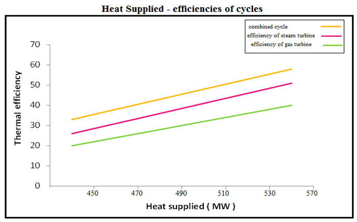
Figure 8 illustrates a comparison of the thermal efficiencies of the gas turbine, steam turbine, and combined cycle. As heat input increases, the combined cycle efficiency consistently remains higher than that of either cycle individually. This is expected; the CCPP recovers waste heat that would otherwise be lost to the environment in a simple gas turbine system. The increase in efficiency with higher heat input is attributed to the optimal utilization of the high temperature exhaust gases. When the turbine inlet temperature rises, the HRSG receives hotter gases and generates more steam at higher enthalpy. This reduces the amount of heat exhausted to the flue and increases the useful work produced by the steam turbine. Therefore, the combined cycle benefits more from higher turbine inlet temperature than either cycle individually.
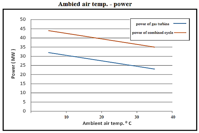
The relationship between AAT and power is depicted in Figure 9. According to the findings from this figure, rising AAT reduces power output for both gas turbine and combined cycle systems. This behavior is attributed to the reduction in air density at higher temperatures. At the same volumetric flow (m3/s), the mass flow rate (kg/s) entering the compressor decreases as AAT increases [19, 20]. This decrease in mass flow reduces turbine output power and increases compressor workload, resulting in a performance drop. The combined cycle exhibits smaller losses than the gas turbine alone because the HRSG mitigates some of the performance degradation by utilizing the hotter exhaust gases. However, overall power output decreases as AAT increases, highlighting the sensitivity of CCPPs to environmental conditions.
Figure 8. Heat supplied over thermal efficiencies of cycle temperature
Figure 9. Relationship between the ambient air temperature (AAT) and turbine power output
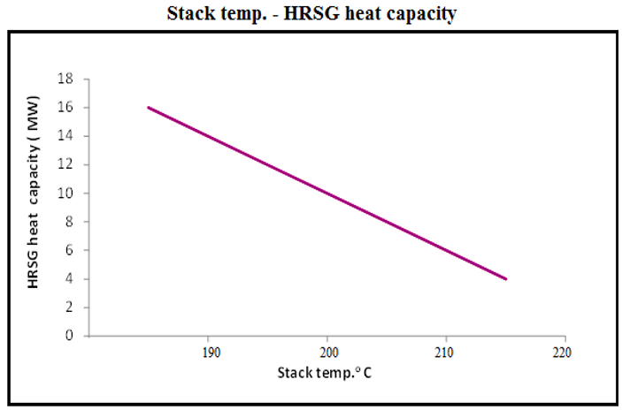
Figure 10. Relationship between stack temperature and Heat Recovery Steam Generator (HRSG) heat capacity
Figure 10 shows the relationship between stack temperature and HRSG heat capacity (MW), demonstrating that the HRSG heat capacity decreases as the stack temperature increases. A higher stack temperature indicates that more heat is being discharged to the environment instead of being recovered in the HRSG. This reduces the energy transferred to the water-steam path and consequently lowers steam production. Ideally, the stack temperature should be maintained as low as possible within practical limits to maximize heat recovery. However, maintaining excessively low stack temperatures requires a larger heat transfer area and may risk condensation of acidic components, highlighting the engineering trade-off between efficiency and cost.
Based on this study, we concluded the following:
1. The combined cycle thermal efficiency reached 63%, compared to 46% for the gas turbine alone.
2. Increasing the turbine inlet temperature improved the overall thermal efficiency by approximately 8–12%, depending on operating conditions.
3. Higher AATs increased exhaust gas energy, enabling up to 12–15% more steam generation in the HRSG.
4. A reduction in pinch point temperature difference from 15 ℃ to 5 ℃ increased heat recovery effectiveness by nearly 10%, but with a corresponding need for larger heat exchange surface area.
5. Optimized HRSG operation increased superheated steam output and improved total plant efficiency by approximately 6–9%.
4.1 Applicability to large applications or systems
This subsection was added to address the real-world applicability of the proposed HRSG and CCPP optimization approach. In this study, the thermodynamic optimization principles used, such as pinch point control, turbine inlet temperature enhancement, and ambient temperature correction, are scalable to larger power stations like multi pressure HRSGs and advanced CCPP configurations. This is due to the underlying heat transfer principles and temperature dependent performance trends remaining consistent across scales; the pinch point optimization approach is directly transferable to multi pressure HRSG designs, industrial cogeneration units, and waste heat recovery systems used in petrochemical, fertilizer, and metallurgical plants. Furthermore, the study highlights that improvements in steam generation and thermal efficiency can offer direct transferability to larger facilities or plants because the underlying thermodynamic relationships, such as heat balances, saturation behavior, and T-S interactions, remain the same.
Practical considerations such as increased HE surface area, capital cost implications, and material limitations at elevated turbine-inlet temperatures are also addressed, demonstrating that the proposed methodology has broad applicability while acknowledging the engineering constraints associated with large scale implementation.
4.2 The approach limitations and future work
In this subsection, the gaps not considered in the present study and that will be addressed in future work are outlined. The current analysis is based on a simplified single pressure, unfired HRSG model without time rate consideration, component degradation or fouling effects over time. Material constraints at elevated turbine inlet temperatures and detailed geometric HRSG design were not explicitly modeled. Furthermore, idealized thermodynamic fluid properties were assumed, and environmental variations beyond ambient temperature were not fully explored.
Future work will focus on developing muti pressure HRSG configurations with time rate thermodynamic simulation to incorporate realistic degradation and efficiency profiles, using operational data from industrial combined-cycle power plants for experimental validations.
|
T |
Temperature, ℃ |
|
Q |
Heat capacity, MW |
|
ṁ |
Mass flow rate, kg‧s-1 |
|
h |
Enthalpy, kJ‧kg-1 |
|
Cpg |
Specific heat of hot gases, kJ‧kg-1‧K-1 |
|
Subscripts |
|
|
pp |
pinch point |
|
g3 |
exit gases temperature from evaporator |
|
s |
water evaporation |
|
gt |
through gas turbine |
|
St |
through steam turbine |
|
g1 |
hot gases inlet to HRSG |
|
g4 |
hot gases exit from HRSG |
|
sh |
steam exit from superheated |
|
Fw |
saturated water |
|
g3 |
gases exit from super heater |
|
ap |
approach temperature |
|
w2 |
exit water temperature from economizer |
|
s2 |
enthalpy at exit evaporator |
|
s1 |
enthalpy at inlet evaporator |
[1] Gicquel, R. (2021). Energy Systems: A New Approach to Engineering Thermodynamics. CRC Press. https://doi.org/10.1201/9781003175629
[2] Manwell, J.F., McGowan, J.G., Rogers, A.L. (2010). Energy conversion technologies. Iowa State University Engineering Notes. https://home.engineering.iastate.edu/~jdm/wind/EnergyConversionTechnologies.pdf.
[3] Wang, T. (2017). The gas and steam turbines and combined cycle in IGCC systems. In Integrated Gasification Combined Cycle (IGCC) Technologies, pp. 497-640. https://doi.org/10.1016/B978-0-08-100167-7.00028-7
[4] Ibrahim, T.K., Rahman, M.M. (2012). Thermal impact of operating conditions on the performance of a combined cycle gas turbine. Journal of Applied Research and Technology, 10(4): 567-577.
[5] Yahya, S.M. (2011). Turbines Compressors and Fans. Tata McGraw Hill Education Pvt. Ltd., New Delhi.
[6] Ibrahim, T.K., Rahman, M.M. (2016). Effects of cycle peak temperature ratio on the performance of combined cycle power plant. International Journal of Automotive and Mechanical Engineering, 13(2): 3389-3400. https://doi.org/10.15282/ijame.13.2.2016.8.0280
[7] Kitto, J.B., Stultz, S.C. (2005). Steam, Its Generation and Use. The Babcock & Wilcox Company, Barberton, Ohio, USA.
[8] Jović, M., Lakovic, M., Bogdanovic-Jovanovic, J. (2016). Review of opportunities for steam condenser performance improvements in power plants. In International Conference Power Plants.
[9] Prabu, S.S., Manichandra, M., Reddy, G.B.P., Vamshi, D.R., Bramham, P.V. (2018). Experimental study on performance of steam condenser in 600 MW Singareni Thermal Power Plant. International Journal of Mechanical Engineering and Technology (IJMET), 9(3): 1095-1106.
[10] Ganapathy, V. (2011). Heat recovery steam generators: Performance management and improvement. In Power Plant Life Management and Performance Improvement, pp. 606-634. https://doi.org/10.1533/9780857093806.5.606
[11] Ali, S.H., Baheta, A.T., Hassan, S. (2014). Effect of low pressure end conditions on steam power plant performance. MATEC Web of Conferences, 13: 02010. https://doi.org/10.1051/matecconf/20141302010
[12] Supper, G.J., Storvick, T.S. (2007). Chapter 7 - Production of electricity. In Sustainable Nuclear Power, pp: 185-200. https://doi.org/10.1016/B978-0-12-370602-7.X5016-9
[13] He, W.F., Xu, L.N., Han, D., Gao, L., Yue, C., Pu, W.H. (2016). Thermodynamic investigation of waste heat driven desalination unit based on humidification dehumidification (HDH) processes. Applied Thermal Engineering, 100: 315-324. https://doi.org/10.1016/j.applthermaleng.2016.02.047
[14] Kotowicz, J., Brzęczek, M. (2018). Analysis of increasing efficiency of modern combined cycle power plant: A case study. Energy, 153: 90-99. https://doi.org/10.1016/j.energy.2018.04.030
[15] Ibrahim, T.K., Mohammed, M.N. (2015). Thermodynamic evaluation of the performance of a combined cycle power plant. International Journal of Energy Science and Engineering, 1(2): 60-70. https://www.scribd.com/document/426274352/we.
[16] Maresh, M. (2015). Streamlining and the impact of steam turbine outlet quality on the yield force of a joined cycle power plant. Master of Technology Dissertation, Pydah College of Engineering. https://recontechnologies.academia.edu/nareshmathukumilli.
[17] Mrzljak, V., Glazar, V., Gubic, T. (2019). Thermodynamics analysis of combined cycle power plant. In 14th International Conference Heat Transfer, Fluid Mechanics and Thermodynamics (HEFAT2019), Wicklow, Ireland, pp. 341-355. https://www.scribd.com/document/733948627/Glazar-Thermodynamic-Analysis-of-Combined-Cycle-Power-Plant.
[18] Rezeka, S.F., El-maghalany, W.M., Abdelhalim, A.M. (2017). Influence of pinch point temperature on the performance of integrated solar combined cycle. International Journal of Engineering Research and Technology, 6(6): 269-272.
[19] Singh, S., Kumar, R. (2012). Ambient air temperature effect on power plant performance. International Journal of Engineering Science and Technology, 4(8): 3916-3923.
[20] FernandezSingh, D.A.P., Foliaco, B., Padillam R.V., Bula, A., Gonzalez-Quiroga, A. (2021). High ambient temperature effects on the performance of a gas turbine-based cogeneration system with supplementary fire in a tropical climate. Case Studies in Thermal Engineering, 4: 101206. https://doi.org/10.1016/j.csite.2021.101206