Dessy Ade Pratiwi* | Ummi Kultsum | Andi Ibrahim Soumi
© 2026 The authors. This article is published by IIETA and is licensed under the CC BY 4.0 license (http://creativecommons.org/licenses/by/4.0/).
OPEN ACCESS
Thermal management remains a critical challenge in fluid-based thermal systems, particularly when low conductivity materials such as polyvinyl chloride (PVC) pipes are employed. This study experimentally investigates the optimization of thermal paste thickness to enhance heat transfer performance in a heated PVC pipe equipped with an aluminum heatsink. The experimental setup consisted of a 500 mm PVC pipe with heated water circulation at a constant flow rate of 760 L/h. A steel plate was attached to the outer pipe surface, followed by the installation of an aluminum heatsink using thermal paste as a thermal interface material (TIM). The thermal paste thickness was varied at 0, 1, 2, and 3 mm to evaluate its influence on temperature distribution and convective heat transfer performance. Temperature measurements were conducted at the water inlet and outlet, as well as along the heatsink surface in both longitudinal and transverse directions using K-type thermocouples integrated with MAX6675 sensors and controlled via an Arduino Uno system. The results reveal that thermal paste thickness significantly affects heat transfer behavior. The 2 mm thermal paste configuration exhibited the most uniform temperature distribution and the highest convective heat transfer coefficient, indicating optimal thermal contact between the pipe, steel plate, and heatsink. In contrast, the absence of thermal paste and excessive paste thickness led to increased thermal resistance and reduced heat transfer performance. These findings demonstrate the importance of thermal interface optimization and provide practical guidance for improving passive cooling performance in PVC-based thermal systems.
thermal management, thermal paste thickness, polyvinyl chloride pipe, heatsink, convective heat transfer
Thermal management and heat transfer enhancement have become increasingly critical in fluid flow based engineering systems due to rising demands for higher efficiency, reliability, and sustainability [1-3]. In energy systems and industrial applications, insufficient heat transfer performance can lead to energy losses, reduced system efficiency, and accelerated material degradation. Conventional heat transfer fluids such as water, oil, and ethylene glycol inherently possess low thermal conductivity, which limits their effectiveness in practical applications [4]. Consequently, extensive research efforts have been directed toward improving heat transfer performance through advanced materials, innovative surface designs, and enhanced thermal management strategies, particularly in energy, electronics cooling, and industrial thermal systems [5, 6].
Among various fluid transport systems, pipes play a central role in heat exchange processes. Polyvinyl chloride (PVC) pipes are widely employed due to their low cost, corrosion resistance, lightweight nature, and ease of installation. However, their application in thermal systems is constrained by their inherently low thermal conductivity, typically around 0.19 W/m·K, which is significantly lower than that of conventional metallic materials such as aluminum or copper [7, 8]. Although several approaches, including the incorporation of conductive fillers and surface metallization, have been proposed to enhance the thermal performance of PVC, these methods often introduce tradeoffs related to mechanical properties, thermal stability, and manufacturing complexity [9-11]. As a result, alternative and more practical strategies are required to improve heat dissipation from PVC based thermal systems without fundamentally altering the base material.
One effective approach to enhance heat transfer from low conductivity substrates is the integration of external heatsinks. Heatsinks increase the effective heat transfer area and promote convective heat dissipation to the surrounding environment. However, the overall thermal performance of a heatsink is strongly influenced by the thermal contact resistance at the interface between the heat source and the heatsink. Microscopic surface roughness and air gaps at the interface can significantly impede heat flow. To mitigate this issue, thermal interface materials (TIMs), such as thermal greases, phase change materials, gap fillers, and metal based interfaces, are commonly employed to fill micro voids and improve interfacial thermal conduction [12]. Previous studies have demonstrated that appropriate TIM selection can substantially reduce thermal resistance and enhance heatsink effectiveness, although TIM performance is sensitive to factors such as surface roughness, pressure, temperature, and material properties [13, 14].
Beyond material selection, the thickness of thermal paste plays a decisive role in determining temperature distribution and heat transfer efficiency. Excessive TIM thickness can increase interfacial thermal resistance, leading to elevated operating temperatures, as observed in Light Emitting Diode (LED) and high power electronic applications [15]. Conversely, reducing TIM thickness has been shown to improve heat dissipation by lowering the thermal resistance between contact surfaces [16]. Nevertheless, overly thin TIM layers may fail to adequately fill surface irregularities, reducing effective contact conductance. Several studies emphasize that optimal thermal performance is achieved within a specific thickness range, where a balance is established between adequate surface conformity and minimal conductive resistance [17, 18]. These findings suggest that TIM thickness optimization is highly application dependent and must be evaluated under realistic operating conditions.
Despite extensive research on TIM optimization in electronic cooling, photovoltaic systems, and micro scale thermal devices, direct investigations focusing on PVC pipe heatsink systems remain scarce. Therefore, the present work contributes novel experimental evidence regarding the influence of thermal paste thickness on temperature distribution and heat transfer performance in a PVC pipe heatsink configuration. Existing studies predominantly address heatsink geometry, advanced surface structures, or fluid dynamics enhancements, while the role of thermal paste thickness in PVC based thermal configurations has received limited attention [19, 20]. Furthermore, many prior works rely heavily on numerical simulations, highlighting the need for experimental validation to ensure practical applicability [21, 22]. In this context, the present study experimentally investigates the optimization of thermal paste thickness to enhance heat transfer performance in a heated PVC pipe equipped with a heatsink. By analyzing temperature distribution and convective heat transfer characteristics under varying thermal paste thicknesses, this research aims to provide practical insights into reducing thermal resistance and improving heat dissipation in PVC based thermal systems.
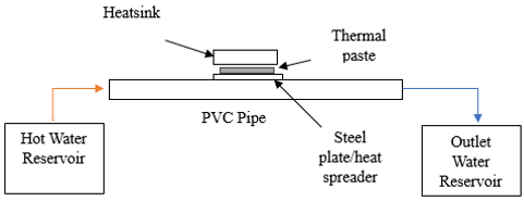
The present study employed an experimental approach to investigate the effect of thermal paste thickness on heat transfer performance in a PVC pipe heatsink system. Figure 1 shows the experimental schematic for this work. The experimental setup consisted of a straight PVC pipe with a total length of 500 mm and an outer diameter of 5/8 inch, which was later converted into millimeter units for data analysis consistency. The pipe served as the main heat transfer channel through which heated water was circulated under controlled conditions.
Hot water was supplied from a reservoir and circulated through the PVC pipe using a direct current (DC) pump and a nominal flow rate of 760 L/h. This configuration was selected to ensure a continuous and stable flow during the experiment while maintaining moderate energy consumption. The pump enabled a closed loop circulation system, allowing the water temperature to be maintained within a warm to hot range throughout the testing period.
Figure 1. Experimental schematic
The heatsink used in this study was an aluminum heatsink with dimensions of 10 × 2 × 0.5 cm. Aluminum was selected due to its relatively high thermal conductivity, lightweight characteristics, and widespread use in passive cooling applications. The compact geometry of the heatsink allowed effective attachment to the outer surface of the PVC pipe via the intermediate steel plate while providing sufficient surface area to promote convective heat dissipation to the surrounding air. The diameter of PVC pipe is 15.87 mm. This configuration ensured consistent thermal contact and enabled a reliable assessment of the influence of thermal paste thickness on heat transfer performance under controlled experimental conditions.
Table 1. Specification of thermal paste
|
Parameter |
Typical Range/Description |
|
Material type |
Silicone-based thermal paste with thermally conductive fillers |
|
Filler material |
Aluminum oxide (Al₂O₃), zinc oxide (ZnO), or ceramic-based particles |
|
Thermal conductivity (W/m·K) |
1.0–5.0 |
|
Operating temperature range (℃) |
−50 to 200 |
|
Density (g/cm³) |
2.0–3.0 |
|
Electrical conductivity |
Electrically insulating |
|
Phase change behavior |
No phase change (grease-type TIM) |
|
Typical application thickness (mm) |
0.1–3.0 |
Thermal paste was applied between the steel plate and the heatsink as a TIM to reduce interfacial thermal resistance. Table 1 shows the specifications of the thermal paste on this work. The specifications of the thermal paste used in this study. The thermal paste is silicone-based and contains thermally conductive filler materials, such as aluminum oxide (Al₂O₃), zinc oxide (ZnO), or ceramic particles, to enhance heat transfer performance. It exhibits a thermal conductivity ranging from 1.0 to 5.0 W/m·K, operates effectively within a temperature range of −50 to 200 ℃, and has a density between 2.0 and 3.0 g/cm³ while maintaining electrical insulation properties. Furthermore, the material remains in a stable grease-like phase without phase change during operation, and it is typically applied with a thickness of 0.1–3.0 mm to ensure efficient thermal contact between surfaces. The thickness of the thermal paste was systematically varied at four levels: 0 mm (without thermal paste), 1 mm, 2 mm, and 3 mm. Each thickness configuration was tested separately under identical operating conditions to ensure a fair comparison of thermal performance. The application of thermal paste was carefully controlled to achieve a uniform layer across the contact surface.
Temperature measurements were conducted at multiple locations to capture the thermal behavior of the system. The inlet and outlet water temperatures were measured to evaluate the heat transfer occurring along the pipe section equipped with the heatsink. In addition, surface temperatures on the heatsink were monitored to assess heat distribution and dissipation characteristics.
All temperature measurements were obtained using K-type thermocouples interfaced with MAX6675 thermocouple amplifier modules. Table 2 describe specification of MAX6675 sensor. The MAX6675 is designed for K-type thermocouples and employs a cold-junction compensation technique, enabling accurate temperature measurements over a range of 0–1024 ℃ with a resolution of 0.25 ℃ and a typical accuracy of ±2 ℃ within its operating range. In addition, the sensor communicates through a digital SPI-compatible interface, operates with a supply voltage of 3.0–5.5 V DC, and can function reliably under ambient temperatures ranging from −20 to 85 ℃. The sensors were connected to an Arduino Uno microcontroller, which was used for data acquisition and real time temperature monitoring. The MAX6675 module was selected due to its reliability and compatibility with Arduino based systems for low to medium temperature measurements.
Table 2. Specification of MAX6675
|
Parameter |
Specification |
|
Sensor type |
K-type thermocouple interface |
|
Measurement principle |
Cold-junction compensated thermocouple measurement |
|
Temperature measurement range |
0-1024 ℃ |
|
Resolution |
0.25 ℃ |
|
Measurement accuracy |
±2 ℃ (typical, within operating range) |
|
Output interface |
Digital (SPI-compatible) |
|
Supply voltage |
3.0–5.5 V direct current (DC) |
|
Thermocouple compatibility |
Standard K-type thermocouples |
|
Operating ambient temperature |
−20 to 85 ℃ |
Temperature data were recorded after the system reached a steady state condition to minimize the influence of transient thermal effects. Each experimental condition was repeated to ensure measurement consistency and reduce random errors.
2.1 Experimental procedure
At the beginning of each test, the water in the reservoir was heated to the desired temperature range and circulated through the system using the DC pump. Once a stable flow rate and temperature condition were achieved, temperature data at the inlet, outlet, and heatsink surface were continuously monitored. Figure 2 shows the procedure of measurement in this work. Measurements were taken over a fixed time interval to ensure steady state behavior.
The experiment was repeated for each thermal paste thickness configuration while keeping all other parameters constant, including flow rate, pipe geometry, and environmental conditions. This approach allowed the influence of thermal paste thickness on heat transfer performance to be isolated and evaluated independently.
Figure 2. Flow of measurement
The experimental system was configured as a closed-loop circulation setup in which heated water was circulated through a PVC pipe using a DC pump operated at a constant nominal flow rate throughout all experiments. The inlet and outlet water temperatures were continuously monitored using K-type thermocouples connected to MAX6675 modules and an Arduino Uno-based data acquisition system to ensure accurate and stable temperature measurements. Prior to data acquisition, the system was allowed to operate until steady-state conditions were achieved, which was defined by negligible variations in temperature readings over a specified period of observation. This procedure minimized the influence of transient thermal effects on the experimental results. In addition, transient temperature data during the initial heating phase were recorded to verify the system’s stabilization behavior before reaching steady state. Temperature measurements were systematically obtained at multiple locations along both the longitudinal and transverse directions of the measurement surface to characterize the heat distribution more comprehensively.
The collected temperature data were used to analyze heat transfer characteristics, including temperature distribution along the system and convective heat transfer performance. The difference between inlet and outlet water temperatures provided an indication of the heat transfer rate, while heatsink surface temperatures were used to assess the effectiveness of thermal conduction and convection mechanisms. Comparative analysis was performed to identify the optimal thermal paste thickness that resulted in enhanced heat transfer performance.
Additional information has been included to clarify the criteria used for establishing steady-state conditions. Temperature measurements were conducted only after the system reached thermal equilibrium, defined as a condition in which temperature fluctuations remained within a narrow range over a specified observation period, thereby minimizing the influence of transient thermal effects on the experimental results. To further enhance the reliability of the study, details regarding the initial temperature stabilization process prior to steady-state operation have also been incorporated. In addition, the description of sensor placement and heat distribution measurement techniques has been expanded to provide a clearer explanation of how temperature data were systematically acquired along both the longitudinal and transverse directions of the heatsink surface. These revisions improve the clarity, reproducibility, and overall methodological robustness of the experimental procedure.
Measurement uncertainty and data accuracy were carefully considered to ensure the reliability of the experimental results [23]. Temperature measurements were performed using K-type thermocouples coupled with MAX6675 modules, which provide a typical temperature resolution of 0.25 ℃ and an accuracy of ±2 ℃ within the operating temperature range specified by the manufacturer. Prior to the experiments, all sensors were checked for consistency by comparing their readings under identical thermal conditions.
The inlet and outlet water temperatures, as well as the heatsink surface temperatures, were recorded after the system reached steady state conditions to minimize transient effects. Steady state was identified when temperature fluctuations remained within ±0.5 ℃ over a sufficiently long observation period. This approach helped reduce uncertainties associated with temporal temperature variations during data acquisition.
Geometric uncertainties related to pipe length, diameter, and thermal paste thickness were minimized through careful measurement and controlled application. The pipe dimensions were measured using a digital caliper, while the thermal paste thickness was applied as uniformly as possible across the contact surface. Although slight local variations in paste thickness may have occurred due to surface roughness and application technique, these effects were assumed to be negligible compared to the overall thermal resistance trends observed in the experiments [24].
Flow rate uncertainty was associated with the DC pump performance, which was operated at a constant nominal flow rate of 760 L/h. Variations in flow rate due to pump instability were considered minimal during steady operation and were assumed to have a limited influence on comparative results, as all experiments were conducted under identical hydraulic conditions.
Overall experimental uncertainty was mitigated by repeating measurements for each thermal paste thickness configuration and maintaining consistent boundary conditions throughout the tests. As the primary objective of this study was comparative performance evaluation rather than absolute heat transfer quantification, the measurement uncertainties were deemed acceptable and sufficient to support the conclusions regarding the optimal thermal paste thickness.
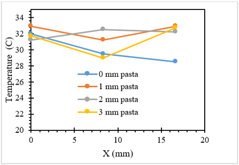
Figure 3 presents the temperature distribution along the X-direction of the heatsink surface for different thermal paste thicknesses, namely 0 mm, 1 mm, 2 mm, and 3 mm. The X-axis represents the measurement positions along the heatsink surface, while the Y-axis indicates the corresponding surface temperature. This figure provides insight into how thermal paste thickness influences heat conduction from the PVC pipe to the heatsink and its subsequent distribution along the heatsink length. For the configuration without thermal paste (0 mm), the temperature decreases progressively along the X-direction. This behavior indicates limited heat spreading across the heatsink surface, which can be attributed to poor thermal contact between the steel plate and the heatsink. The absence of thermal paste likely results in air gaps at the interface, increasing thermal contact resistance and restricting efficient heat conduction away from the heat source. Consequently, the heat transfer along the heatsink becomes less effective, leading to a pronounced temperature gradient.
Figure 3. Temperature on the X-axis
When thermal paste is applied with a thickness of 1 mm, the temperature distribution shows a more stable profile compared to the no-paste condition. Although a slight temperature drop is observed at intermediate positions, the overall temperature level remains higher than that of the 0 mm case. This suggests that the thermal paste partially fills surface irregularities, improving interfacial contact and enhancing heat conduction from the pipe to the heatsink. However, the observed temperature reduction at the mid-section indicates that the thermal paste layer may still be insufficient to fully optimize heat spreading along the heatsink. The most uniform and elevated temperature distribution is observed for the 2 mm thermal paste configuration. The temperature remains relatively consistent along the X-direction, indicating effective heat transfer and improved thermal spreading across the heatsink surface. This behavior implies that a 2 mm thermal paste thickness provides an optimal balance between minimizing interfacial thermal resistance and avoiding excessive conductive resistance within the paste layer. As a result, heat is transferred more uniformly from the pipe to the heatsink, allowing the entire heatsink surface to actively participate in convective heat dissipation. In contrast, the 3 mm thermal paste configuration exhibits higher temperatures near the measurement endpoints but a noticeable temperature dip at intermediate positions. This non-uniform distribution suggests that excessive thermal paste thickness introduces additional conductive resistance, limiting heat flow from the steel plate to certain regions of the heatsink. Although the initial contact area may receive sufficient heat, the thicker paste layer reduces effective heat spreading, resulting in localized thermal gradients along the X-direction.
Overall, the results demonstrate that thermal paste thickness plays a crucial role in controlling temperature distribution along the heatsink surface. An insufficient or excessive thermal paste thickness leads to non-uniform temperature profiles and reduced heat transfer effectiveness. Among the tested configurations, a thermal paste thickness of 2 mm provides the most favorable temperature distribution, indicating superior thermal contact and enhanced heat transfer performance. These findings support the conclusion that careful optimization of thermal interface thickness is essential for improving the thermal efficiency of PVC pipe heatsink systems.
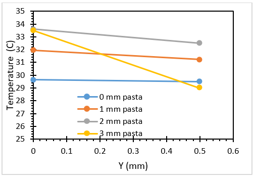
Figure 4 illustrates the temperature distribution along the Y-direction of the heatsink surface for different thermal paste thicknesses, namely 0 mm, 1 mm, 2 mm, and 3 mm. The Y-axis represents the transverse distance from the base of the heatsink, while the corresponding temperatures reflect the effectiveness of heat spreading and dissipation across the heatsink thickness.
Figure 4. Temperature on the Y-axis
For the configuration without thermal paste (0 mm), the temperature profile remains relatively flat along the Y-direction. This behavior suggests limited heat conduction from the interface into the upper regions of the heatsink, indicating that thermal contact resistance at the interface restricts effective heat penetration through the heatsink thickness. As a result, only a portion of the heatsink near the contact area actively participates in heat dissipation. When a 1 mm thermal paste layer is applied, a moderate temperature gradient is observed along the Y-axis. The temperature decreases slightly with increasing distance from the base, indicating improved heat conduction into the heatsink compared to the no-paste condition. This suggests that the thermal paste partially enhances interfacial contact, allowing heat to propagate more effectively across the heatsink cross-section, although the overall heat spreading remains limited.
The 2 mm thermal paste configuration exhibits the highest temperature levels and a relatively gradual temperature decrease along the Y-direction. This indicates that heat is transferred efficiently from the PVC pipe through the steel plate and into the heatsink, allowing a larger portion of the heatsink volume to be thermally activated. The more uniform temperature distribution suggests that the thermal paste thickness of 2 mm minimizes interfacial thermal resistance while maintaining sufficient conductive performance within the paste layer, resulting in effective heat spreading through the heatsink thickness. In contrast, the 3 mm thermal paste configuration shows a pronounced temperature drop along the Y-direction, particularly at the outer edge of the heatsink. Although the temperature near the base is relatively high, the steeper gradient indicates that excessive thermal paste thickness introduces additional conductive resistance, limiting heat flow into the upper regions of the heatsink. Consequently, heat dissipation becomes less uniform, and the effective heat transfer area of the heatsink is reduced.
Overall, the temperature distributions observed along the Y-axis reinforce the findings obtained from the X-direction analysis. Both results demonstrate that thermal paste thickness strongly influences heat spreading within the heatsink. Among the tested configurations, a thermal paste thickness of 2 mm provides the most favorable balance between thermal contact improvement and conductive resistance, leading to enhanced heat distribution and improved thermal performance of the PVC pipe heatsink system.
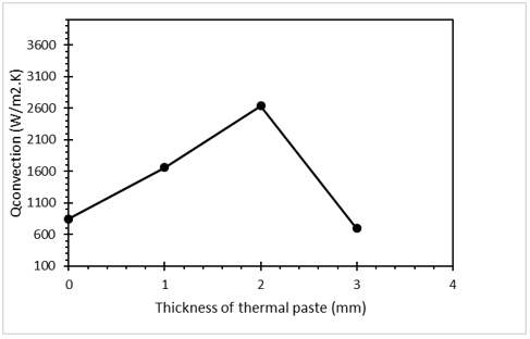
Figure 5 shows the variation of the convective heat transfer coefficient as a function of thermal paste thickness applied between the steel plate and the aluminum heatsink. The results clearly indicate that thermal paste thickness has a significant influence on the convective heat transfer performance of the PVC pipe heatsink system.
Figure 5. Heat transfer
In the absence of thermal paste (0 mm), the convective heat transfer coefficient exhibits the lowest value. This behavior can be attributed to the presence of microscopic air gaps at the interface between the steel plate and the heatsink, which introduce high thermal contact resistance. As a result, heat transfer from the pipe to the heatsink is limited, leading to a reduced surface temperature of the heatsink and, consequently, a lower convective heat transfer coefficient.
When a thermal paste thickness of 1 mm is applied, a noticeable increase in the convective heat transfer coefficient is observed. The thermal paste fills surface irregularities and improves interfacial contact, thereby reducing thermal resistance and allowing more heat to be conducted into the heatsink. This enhanced heat conduction increases the effective temperature difference between the heatsink surface and the surrounding air, resulting in improved convective heat transfer.
The maximum convective heat transfer coefficient is achieved at a thermal paste thickness of 2 mm. At this thickness, the thermal paste provides an optimal balance between minimizing interfacial thermal resistance and maintaining sufficient conductive performance within the paste layer. The improved thermal contact enables a more uniform temperature distribution across the heatsink surface, as observed in the temperature profile analyses along both the X- and Y-directions. Consequently, a larger effective surface area participates in convective heat dissipation, leading to the highest convective heat transfer coefficient among the tested configurations.
In contrast, increasing the thermal paste thickness to 3 mm results in a significant reduction in the convective heat transfer coefficient. Although the thermal paste continues to fill interfacial gaps, the excessive thickness introduces additional conductive resistance within the paste layer itself. This increased resistance limits heat flow from the steel plate to the heatsink, reducing the heatsink surface temperature and diminishing the driving force for convection. As a result, the convective heat transfer performance deteriorates despite the presence of thermal paste.
The analysis was performed under steady-state conditions to ensure that the reported results were not influenced by transient thermal behavior. Steady state was confirmed when temperature fluctuations remained within a narrow range over a defined observation period prior to data recording. This approach ensures that all presented temperature and heat transfer characteristics represent stable operating conditions of the system. In addition, the initial transient temperature behavior was examined to verify the stabilization process, showing a gradual convergence toward equilibrium before steady-state data acquisition. This confirmation of thermal stability strengthens the validity of the experimental results and supports the reliability of the measured data. Furthermore, the spatial temperature distribution was evaluated based on measurements obtained at multiple points along both the longitudinal and transverse directions of the heatsink surface, allowing a more comprehensive assessment of heat spreading behavior under the tested conditions.
Overall, the observed trend demonstrates that thermal paste thickness plays a critical role in determining convective heat transfer performance. An insufficient or excessive thermal paste thickness leads to suboptimal heat transfer, while an intermediate thickness yields superior performance. Based on the experimental results, a thermal paste thickness of 2 mm is identified as the optimal configuration for maximizing convective heat transfer in the PVC pipe heatsink system. This finding highlights the importance of thermal interface optimization in enhancing the effectiveness of passive cooling systems.
The experimental results obtained in this study are consistent with trends reported in previous investigations on TIMs, particularly regarding the role of interface quality in enhancing heat transfer performance. Earlier studies on metal-metal and electronic cooling interfaces have demonstrated that the application of thermal paste significantly reduces thermal contact resistance by filling microscopic air gaps, thereby improving heat conduction across the interface. For instance, Asif et al. [25] reported a noticeable improvement in interfacial thermal conductance when thermal paste was introduced, compared to direct surface contact without TIM, although excessive material thickness was found to limit further performance gains. Similar behavior is observed in the present study, where the absence of thermal paste results in lower heat transfer performance, while moderate paste thickness enhances thermal energy transport to the heatsink surface.
Furthermore, studies focusing on the optimization of thermal paste thickness in electronic cooling systems have highlighted the existence of an optimal thickness range that balances contact resistance reduction and internal conductive resistance within the TIM layer. Singhal et al. [26] showed that increasing TIM thickness beyond an optimal value leads to a decline in thermal performance due to the dominance of conductive resistance within the interface layer itself. The findings of the present work align closely with this principle, as the highest convective heat transfer coefficient was achieved at a thermal paste thickness of 2 mm, while further thickness increase resulted in performance degradation. This agreement suggests that, despite differences in application scale and base material, the fundamental heat transfer mechanisms governing TIM optimization remain consistent. Importantly, this study extends prior findings by experimentally validating these mechanisms in a PVC pipe heatsink system, which has been scarcely addressed in earlier literature.
The optimization of thermal interface thickness plays a significant role in enhancing heat transfer performance in PVC pipe–heatsink systems. The results indicate that the thermal interface layer influences both interfacial thermal resistance and conductive resistance, thereby affecting temperature distribution and overall thermal management effectiveness. These findings contribute to a better understanding of thermal interface behavior in systems involving low thermal conductivity substrates and provide practical guidance for the design of passive cooling applications. Future research should focus on the evaluation of TIMs with higher thermal conductivity, the investigation of alternative heatsink configurations and operating conditions, and the integration of numerical simulations with experimental approaches. Such studies would provide deeper insights into the underlying heat transfer mechanisms and support the development of more efficient and reliable thermal management systems.
The authors would like to express their sincere gratitude to the Ministry of Higher Education, Science, and Technology of the Republic of Indonesia (Kemdiktisaintek), through the Directorate General of Research and Development, for supporting this publication under the 2025 Reputable Journal Publication Assistance Program, based on Decree Number 0488/C/DT.06.01/2025 concerning the Recipients of Publication Assistance for Reputable Journals in 2025.
[1] Rebay, M., Kakac, S., Cotta, R.M. (2016). Microscale and Nanoscale Heat Transfer: Analysis, Design, and Application. Taylor & Francis. https://doi.org/10.1201/b19261
[2] Sarjito, S. (2013). An investigation of the scope for improvement of the performance of multi-stage downdraught evaporative coolers using CFD. Applied Mechanics and Materials, 315: 835-840. https://doi.org/10.4028/www.scientific.net/AMM.315.835
[3] Sarjito, S., Putro, S., Nugraha, N.A. (2014). An experimental study of heat transfer coefficient in a bubble flow throughout an annulus pipe heated at inner wall. Applied Mechanics and Materials, 660: 654-658. https://doi.org/10.4028/www.scientific.net/AMM.660.654
[4] Kukulka, D.J., Smith, R. (2012). Development and evaluation of enhanced heat transfer tubes for transitional Reynolds number flow. Chemical Engineering Transactions, 29: 1489-1494. https://doi.org/10.3303/CET1229249
[5] Castillo-Orozco, E., Garzón, C., Garavitto, O., Kourmpetis, M., Gronfula, M. (2025). Computational design and optimization of a dual-inlet liquid-cooled heat sink with flat jets for electronics. In ASME 2025 Heat Transfer Summer Conference collocated with the ASME 2025 19th International Conference on Energy Sustainability, Westminster, Colorado, USA. https://doi.org/10.1115/HT2025-157210
[6] Khanafer, K., Vafai, K. (2011). A critical synthesis of thermophysical characteristics of nanofluids. International Journal of Heat and Mass Transfer, 54(19-20): 4410-4428. https://doi.org/10.1016/j.ijheatmasstransfer.2011.04.048
[7] Wang, N., Jiang, P., Zhang, P., Qi, S., Xu, J., Chen, S., Sheng, X., Gao, J., Gao, H. (2025). Synthesis of multifunctional heat stabilizer bio-based Ade-Zn and its application in PVC. Macromolecular Rapid Communications, 46(21): e00487. https://doi.org/10.1002/marc.202500487
[8] Agoudjil, B., Datcu, S., Boudenne, A., Ibos, L., Candau, Y. (2006). Parametric estimation of thermoradiative properties of materials based on harmonic excitation. Review of Scientific Instruments, 77(3): 035106. https://doi.org/10.1063/1.2176060
[9] Anand, S., Gopalan, V., Pitchumani, S.V. (2025). Optimization of thermal conductivity in coir fibre-reinforced PVC composites using advanced computational techniques. Scientific Reports, 15(1): 1-21. https://doi.org/10.1038/s41598-025-01471-8
[10] dos Santos, L.P., Flores-Sahagun, T.S., Paredes, R.S.C., Satyanarayana, K.G., Ferla, S.M.B. (2019). Study on the deposition of stainless steel on polymeric substrates by arc electric thermal spraying. Materials Research Express, 6(10): 105314. https://doi.org/10.1088/2053-1591/ab2a2f
[11] Chen, J., Liu, J., Xu, X., Liu, K., Wang, Z. (2023). Effects of temperature and pressure on interfacial thermal resistance of thermal interface materials in coupled heat transfer process with vapor chamber. Applied Thermal Engineering, 239: 122104. https://doi.org/10.1016/j.applthermaleng.2023.122104
[12] Liu, D., Zhang, J., Zeng, J., Sun, R., Xu, J., Yao, Y., Zeng, X. (2023). Conjugated small molecule crystals as a coupling layer between carbon-based thermal interface materials and heat sink. In 2023 24th International Conference on Electronic Packaging Technology (ICEPT), Shihezi City, China, pp. 1-5. https://doi.org/10.1109/ICEPT59018.2023.10492322
[13] Khuu, V., Osterman, M., Bar-Cohen, A., Pecht, M. (2007). Thermal performance measurements of thermal interface materials using the laser flash method. In ASME 2007 InterPACK Conference collocated with the ASME/JSME 2007 Thermal Engineering Heat Transfer Summer Conference, Vancouver, British Columbia, Canada, pp. 405-414. https://doi.org/10.1115/IPACK2007-33554
[14] Swamy, M.C.K., Satyanarayan. (2019). A review of the performance and characterization of conventional and promising thermal interface materials for electronic package applications. Journal of Electronic Materials, 48(12): 7623-7634. https://doi.org/10.1007/s11664-019-07623-7
[15] Lee, D.K., Kim, T.K., Lee, J.M., Cha, Y., Kwak, J.S. (2019). Improvement in the heat dissipation of matrix LED headlamps for vehicles according to the thickness and thermal conductivity of thermal interface materials. Japanese Journal of Applied Physics, 58: SCCC20. https://doi.org/10.7567/1347-4065/ab12c7
[16] Abadi, P.P.S.S., Leong, C., Chung, D. (2008). Factors that govern the performance of thermal interface materials. Journal of Electronic Materials, 38(1): 175-192. https://doi.org/10.1007/s11664-008-0563-8
[17] Liu, B., Gao, W., Duan, L., Li, Q., Gong, S., Li, R., Zhang, J. (2025). Performance analysis of Gallium-based liquid metal as thermal interface material for chip heat dissipation. International Journal of Thermal Sciences, 218: 110121. https://doi.org/10.1016/j.ijthermalsci.2025.110121
[18] Maalej, S., Saad, I., Nasri, M., Zaghdoudi, M. (2022). Combined effects of heat input and clamping pressure on the thermal performance of phase change thermal interface materials for electronics cooling applications. Thermal Science and Engineering Progress, 28: 101168. https://doi.org/10.1016/j.tsep.2021.101168
[19] Boonlom, K., Viratikul, R., Khonrang, J., Amsdon, T., Chudpooti, N., Rungraungsilp, S., Robertson, I., Janpugdee, P., Somjit, N. (2024). Optimization of heatsink design for enhanced thermal management in LED-based optical wireless communication systems for in-pipe inspection robots. In 2024 Research, Invention, and Innovation Congress: Innovative Electricals and Electronics (RI2C), Bangkok, Thailand, pp. 310-315. https://doi.org/10.1109/RI2C64012.2024.10784399
[20] Huang, H., Fu, H., Li, H., Pan, C., Sun, Z., Ren, X. (2025). Numerical study on a PV/T using microchannel heat pipe. Processes, 13(11): 3402. https://doi.org/10.3390/pr13113402
[21] Al-Haidari, S.R., Al-Obaidi, A.R. (2024). Analysis of thermohydraulic flow and enhancement heat performance in 3D dimple tube based on varying geometrical configurations. Heat Transfer, 53(6): 3287-3316. https://doi.org/10.1002/htj.23085
[22] Altaf, K., Tariq, A., Ahmad, S.W., Hussain, G., Ratlamwala, T., Ali, H.M. (2022). Thermal and hydraulic analysis of slotted plate fins heat sinks using numerical and experimental techniques. Case Studies in Thermal Engineering, 35: 102109-102109. https://doi.org/10.1016/j.csite.2022.102109
[23] Nguyen, V., Shaker, M.H., Hüllermeier, E. (2021). How to measure uncertainty in uncertainty sampling for active learning. Machine Learning, 111(1): 89-122. https://doi.org/10.1007/s10994-021-06003-9
[24] Zhao, J., Zhao, R., Huo, Y., Cheng, W. (2019). Effects of surface roughness, temperature and pressure on interface thermal resistance of thermal interface materials. International Journal of Heat and Mass Transfer, 140: 705-716. https://doi.org/10.1016/j.ijheatmasstransfer.2019.06.045
[25] Asif, M., Husain, S., Rehman, S., Hussain, T., Mohd, R. (2024). Experimental studies on selected thermal interface materials. Thermal Science, 28(4 Part A): 2857-2866. https://doi.org/10.2298/tsci230911284a
[26] Singhal, V., Siegmund, T., Garimella, S.V. (2004). Optimization of thermal interface materials for electronics cooling applications. IEEE Transactions on Components and Packaging Technologies, 27(2): 244-252. https://doi.org/10.1109/TCAPT.2004.828587