Numerical Assessment of Thermal-Hydraulic Performance of SiO2-Water Nanofluid in a Channel with Trapezoidal Obstacles

Ahmed Mustaffa Saleem | Mohammed Taha Luhaibi* | Zeena Ahmed Mohammed
© 2026 The authors. This article is published by IIETA and is licensed under the CC BY 4.0 license (http://creativecommons.org/licenses/by/4.0/).
OPEN ACCESS
This study numerically investigates forced convection heat transfer and turbulent flow of a SiO₂-water nanofluid in a channel with trapezoidal obstacles. A two-dimensional standard k-ε turbulence model with improved wall treatment was used and validated against experimental data. Simulations covered Reynolds numbers (Re) in the range of (4000 ≤ Re ≤ 10000), considering inline and staggered obstacle arrangements, nanoparticle volume fractions (1–4%), nanoparticle diameters (20–40 nm), and obstacle pitch (8–12 mm). The staggered configuration enhanced thermal-hydraulic performance, yielding an 8.61% higher Nusselt number (Nu) and a lower friction factor (f) than the inline arrangement. Increasing nanoparticle volume fraction from 1% to 4% at a fixed 30 nm diameter improved Nu by 11.13% with negligible hydraulic penalty. A smaller nanoparticle with a diameter of 20 nm improved heat transfer by 4.54% relative to 40 nm due to enhanced Brownian motion. The thermal performance factor (TPF) exceeded unity for all cases, reaching a maximum of 1.549 for the staggered configuration at Re = 4000, 4% volume fraction, and 20 nm diameter. An obstacle pitch of 10 mm provided the best thermal enhancement with lower pressure drop at higher Re. The findings confirm that nanofluids combined with trapezoidal obstacles, particularly in a staggered arrangement, offer a promising balance between heat transfer enhancement and pressure drop for compact heat exchanger-related applications.
nanofluid flow, heat transfer enhancement, SiO2 nanoparticles, trapezoidal obstacles, thermal performance factor, turbulent convection
Heat transfer enhancement using water-based nanofluids has attracted sustained attention due to the potential to improve thermal performance and enable more compact heat exchanger designs [1]. Among the wide range of nanoparticles studied, silicon dioxide (SiO₂) stands out as the most promising, as it is stable, non-toxic, and exhibits predictable dispersion behavior, making it a very useful choice for engineering applications [2]. For turbulent internal flows, a combination of these nanoparticle-induced thermophysical effects with engineered geometric modifications, such as obstacles, corrugations, fins, and baffles, can also be used to enhance further convective heat transfer through turbulent mixing and boundary-layer disruption [3].
Numerous numerical and experimental studies have been conducted to assess the performance of nanofluids for heat transfer enhancement under different geometrical and operating conditions. Hamood et al. [4] numerically investigated the laminar flow of Ag nanoparticles through a channel with triangular obstacles and compared results for three obstacle heights (4 µm, 6 µm, 8 µm) and nanoparticle volume fractions (2% to 6%). The results indicated that maximum heat transfer occurs at a nanoparticle volume fraction of 6% when the nanoparticle diameter is 25 nm, and the obstacle height is 8 µm. Barhdadi et al. [5] similarly showed that turbulence formation in the flow induced by channel obstacles increased convective heat transfer, with the effect more pronounced at higher Re numbers. Yarmand et al. [6] presented numerical results for SiO₂-water nanofluids. They reported that they have the highest Nusselt number (Nu) among different types of nanoparticles under turbulent flow, reinforcing their suitability for heat exchanger applications. Ajeel et al. [7] found that semicircular corrugated channels significantly improved heat transfer by enhancing fluid mixing. Alshukri et al. [8] also confirmed that the TPF reached a maximum of 2 over the Re number range of 5000 to 50000 using rectangular obstacles in the channel.
Further, Abchouyeh et al. [9] simulated CuO water nanofluid flow using the Lattice Boltzmann Method (LBM) past sinusoidal obstacles and concluded that enhancement in the average Nu number by increasing Re number and nanoparticle concentration was quite evident. Baghban et al. [10] predicted heat transfer in SiO₂ nanofluid using a Least Squares Support Vector Machine (LSSVM) model, which showed good agreement with experimental results. Akbari et al. [11] studied forced convective heat transfer over semi-attached ribs. A trade-off between heat transfer augmentation and friction factor (f) increase was reported. Simultaneously, Kumar and Kumar [12] also noted in their review article that SiO₂-water nanofluid consistently yields better results than the base fluid in forced convection and emphasized the lack of studies on the simultaneous effects of turbulence and geometrical modifications. Esfeh et al. [13] also conducted a numerical study on a nanofluid with natural convection in the presence of cylindrical obstacles. They observed that nanoparticle volume fraction and Rayleigh number positively improve heat transfer. Ali and Alsaffawi [14] experimentally studied a hybrid nanofluid. They concluded that the increase in the friction factor was proportional to the increase in the average Nu with increasing Re and nanoparticle concentration.
Lafta [15] studied the influence of square, rectangular, and triangular obstacles. Results demonstrated that their use increases local turbulence in the flow, thus enhancing convective heat transfer. Abedalh et al. [16] reported a significant increase in heat transfer (approximately 14%) and a moderate increase in pressure drop (approximately 4%) with the use of hybrid nanofluids. Shaalan et al. [17] reported that the use of CuO nanofluids in heat pumps increased efficiency by 22%. In contrast, Jehad and Hashim [18] numerically modeled the forced convection of nanofluids and verified the dependence of thermal performance on Reynolds number (Re). Vajjha et al. [19] conducted an experimental study to develop new empirical correlations for turbulent nanofluid convection over a range of Re numbers, which can be used to validate simulation results. Abdullah et al. [20] studied numerically the heat transfer performance of a hybrid nanofluid inside a wavy micro-channel. The results reveal that nanoparticles with a concentration of 3% at Re = 1800 enhance the heat transfer coefficient by 59.5% and help improve Nu by 42.25%.
Berrehal and Sowmya [21] focused on nanofluid flow in a mini-channel and employed an advanced homotopy-based modeling technique to investigate heat transport at the micro-scale. Aghaei et al. [22] numerically studied nanofluid flow through square barriers, finding a proportional relationship between nanoparticle concentration and the convective heat transfer rate. Finally, Vanaki et al. [23] reported on nanofluids. They concluded that a wavy channel is superior to a smooth channel, and that Re in the range of 6000 to 18000 is more promising for higher heat transfer.
Unlike rectangular obstacles that promote large stagnant recirculation zones and sharp-corner stress concentrations, or triangular obstacles that induce aggressive pressure drops, trapezoidal obstacles offer a favorable compromise: the sloped walls gradually redirect flow, reducing form drag and manufacturing complexity while still disrupting the thermal boundary layer effectively [3, 8].
While the literature extensively reports studies on heat transfer enhancement using either geometric obstacles (rectangular, triangular, sinusoidal corrugations) or nanofluid addition independently, the systematic parametric investigation combining trapezoidal obstacle geometry with SiO₂-water nanofluid (varying both particle size and volume fraction) and comparing inline/staggered arrangements remains unexplored. To address this gap, the current research numerically analyzes the impact of Re (4000 ≤ Re ≤ 10000) on average Nu, f, and TPF of SiO2-water nanofluids during turbulent flow in a channel with trapezoidal obstacles in inline and staggered arrangements. Moreover, a systematic study was done on the effects of the nanoparticle size (20, 30, and 40 nm) and volume fraction (0 to 4%). Application of trapezoidal obstacles is a geometric arrangement that is yet to be fully discussed in the existing literature in relation to rectangular and triangular baffles, and the joint evaluation of nanoparticle size and volume fraction is informative in the context of optimization of thermal-hydraulic performance.
2.1 Geometric description of the channel
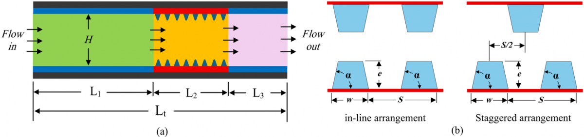
The current numerical study utilizes a two-dimensional computational framework to investigate forced convection and thermal transport characteristics of water-based silicon oxide (SiO2) nanofluids. The physical domain consists of a horizontal rectangular duct featuring a series of trapezoidal obstacles mounted on both the upper and lower surfaces, as illustrated in Figure 1. The primary geometric parameters include a channel height (H) of 10 mm, with the obstacle width (w) and height (e) defined as 0.4H and 0.1H, respectively. To facilitate a fully developed flow profile, a hydrodynamic entry length of 20H is established prior to the first obstacle. Furthermore, an exit section of 5H is maintained downstream of the final obstacle to mitigate the influence of back-pressure and potential flow reversal at the outlet boundary. The total length of the active obstacle section is designated as 11H. Table 1. Shows the geometric parameters of the channel. The thermal-hydraulic performance is evaluated across five distinct independent variables: Re, nanoparticle diameter, volume fraction, obstacle configuration (inline vs. staggered), and obstacle pitch. As depicted in Fig. 1, the trapezoidal obstacles are characterized by a 30° inclination angle. Flow enters the domain via a velocity inlet (4000 ≤ Re ≤ 10000) and exits through a pressure outlet boundary. The incoming flow is assumed to be turbulent, featuring a 5% turbulence intensity at an ambient temperature Tin of 300 K. A constant heat flux is applied to the channel walls, and no-slip conditions are imposed.
Figure 1. Configuration of the enhanced channel with flow obstacles: (a) layout, (b) shapes and dimensions
Table 1. Channel geometric parameters
|
Parameter |
Symbol |
Value |
|
Channel height |
H |
10 mm |
|
Obstacle width |
w |
4 mm (0.4H) |
|
Obstacle height |
e |
1 mm (0.1H) |
|
Obstacle inclination angle |
α |
30° |
|
Baseline pitch (variable) |
S |
8, 10, 12 mm |
|
Entry section length |
L1 |
200 mm (20H) |
|
Obstacle section length |
L2 |
110 mm (11H) |
|
Exit section length |
L3 |
50 mm (5H) |
|
Total computational domain length |
Lₜ |
360 (mm) |
2.2 Governing equations
Figure 1 presents a schematic of a two-dimensional channel with a trapezoidal obstacle model studied in this work. The following assumptions were applied to operating conditions of the enhanced channel: (i) flow in the channel is at steady-state; (ii) fluid is incompressible, and it remains single-phase throughout the channel; (iii) fluid properties and channel material properties are independent of temperature; (iv) a constant heat flux boundary condition is applied to the upper and lower walls of the channel.
The thermal transport and fluid dynamics within the channel are described using a group of governing equations formulated in the Cartesian coordinate framework [24-26], which include:
Continuity equation:
$\frac{\partial}{\partial x_i}\left(\rho u_i\right)=0$ (1)
Momentum equation:
$\rho \frac{\partial}{\partial x_i}\left(u_i u_j\right)=-\frac{\partial p}{\partial x_i}+\frac{\partial}{\partial x_j}\left(-\rho \overline{u_{\imath}^{\prime} u_{\jmath}^{\prime}}\right)+\frac{\partial}{\partial x_j}\left[\left(\frac{\partial u_i}{\partial x_j}+\frac{\partial u_j}{\partial x_j}\right) \mu\right]$ (2)
$\frac{\partial}{\partial x_i}\left(\rho u_i T\right)=\frac{\partial}{\partial x_j}\left[\left(\frac{\mu}{\mathrm{Pr}}+\frac{\mu_i}{\mathrm{Pr}_i}\right)\right] \frac{\partial T}{\partial x_j}$ (3)
The Reynolds-averaged method of turbulence modeling necessitates that the Reynolds stresses $\left(-\rho \overline{u_{\imath}^{\prime} u_{\jmath}^{\prime}}\right)$ appearing in Eq. (2) be modeled. Closure of these equations was obtained by selecting the k-ε turbulence model. A popular approach is to use the Boussinesq hypothesis to model the Reynolds stresses in terms of the mean velocity gradients:
$\left(-\rho \overline{u_{\imath}^{\prime} u_{\jmath}^{\prime}}\right)=\mu_i\left(\frac{\partial u_i}{\partial x_j}+\frac{\partial u_j}{\partial x_i}\right)$ (4)
The turbulent viscosity $\mu_i$ is determined from an appropriate turbulence model, expressed as:
$\mu_i=\rho C_\mu \frac{k^2}{\varepsilon}$ (5)
where, k from the modeled transport equation for TKE is given by:
$\frac{\partial}{\partial x_i}\left[\rho k u_i\right]=\frac{\partial}{\partial x_j}\left[\left(\mu+\frac{\mu_i}{\sigma_k}\right) \frac{\partial k}{\partial x_j}\right]+G_k-\rho \varepsilon$ (6)
Similarly, the dissipation rate $epsilon$ of TKE is governed by:
$\frac{\partial}{\partial x_i}\left(\rho \varepsilon u_i\right)=\frac{\partial}{\partial x_j}\left[\left(\mu+\frac{\mu_i}{\sigma_k}\right) \frac{\partial \varepsilon}{\partial x_j}\right]+C_{1 \varepsilon} \frac{\varepsilon}{k} G_k-C_{2 \varepsilon} \rho \frac{\varepsilon^2}{k}$ (7)
In these expressions, $G_k$ represents the production rate of TKE, while $\rho \varepsilon$ is its destruction rate. $G_k$ is defined as:
$G_k=-\rho u_i u_j \frac{\partial u_j}{\partial x_i}$ (8)
The boundary values of turbulent quantities close to the wall are imposed by using the enhanced wall treatment method. The empirical constants Cμ = 0.09, C1ε = 1.44, C2ε = 1.92, σk = 1.0, σε = 1.3, and Pri = 0.9 are used in the turbulence transport equations [27].
The hydraulic diameter (Dh) of a rectangular channel of one obstacle period is defined according to the study [28] as:
$D_h=\frac{4 A}{P_h}$ (9)
The velocity based on Re, Dh, and the nanofluid effective properties is calculated as follows [29]:
$u_m=\frac{\mu_{n f} R e}{\rho_{n f} D_h}$ (10)
The average friction factor (fav) for turbulent flow regime is calculated based on the pressure drop over the length L [30, 31]:
$f_{a v}=\frac{2 D_h}{L} \frac{\Delta P}{\rho u_m^2}$ (11)
where, ΔP = Pin - Pout is the pressure difference between the inlet and outlet
To evaluate the heat transfer characteristics, the local heat transfer coefficient h(x) and the local Nusselt number Nu(x) are defined [32]:
$h(x)=\frac{Q}{T_w(x)-T_{b, n f}(x)}$ (12)
$N u(x)=\frac{h(x) D_h}{\lambda_{n f}}$ (13)
Whereas the average heat transfer coefficient (hav) is calculated as follows by integrating local values along the channel length L [33]:
$h_{a v}=\frac{1}{L} \int_0^L h(x) d x$ (14)
Consequently, the average Nusselt number (Nuav) could thus be defined as [34]:
$N u_{a v}=\frac{h_{a v} D_h}{\lambda_{n f}}$ (15)
The overall hydrothermal performance of the channel with inserted obstacles can be quantified by introducing the thermal performance factor (TPF). TPF essentially measures how much more heat transfer enhancement could be gained with how much pressure drop penalty when compared to the plain channel [35-37]:
$T P F=\frac{N u_{a v}}{N u_p}\left(\frac{f_{a v}}{f_p}\right)^{-\frac{1}{3}}$ (16)
where, Nup and fp represent the ‘Nusselt number (Nu)’ and friction factor of a smooth plain channel, respectively.
2.3 Thermophysical properties of nanofluids
For a nanofluid with spherical particles, the specific heat capacity and effective density may be determined using the following formulae [38, 39]:
$\rho_{n f}=(1-\phi) \rho_{b f}+\phi \rho_{n p}$ (17)
$\left(c_p\right)_{n f}=\left[(1-\phi)\left(\rho c_p\right)_{b f}+\phi\left(\rho c_p\right)_{n p}\right] / \rho_{n f}$ (18)
The effective thermal conductivity coefficient $\left(\lambda_{n f}\right)$ is expressed as a two-term function, where the first term represents the static part, and the second is related to Brownian motion. The term related to Brownian motion considers the particle size, particle volumetric concentration, temperature and base fluid properties, together with the properties of nanoparticles affected by Brownian motion. So, the effective thermal conductivity of nanofluid is determined by the following equations [23]:
$\lambda_{n f}=\lambda_{s t}+\lambda_{B r}$ (19)
where,
$\lambda_{s t}=\lambda_{b f}\left[\frac{\left(2 \lambda_{b f}+\lambda_{n p}\right)-2 \phi\left(\lambda_{b f}-\lambda_{n p}\right)}{\left(2 \lambda_{b f}+\lambda_{n p}\right)+\phi\left(\lambda_{b f}-\lambda_{n f}\right)}\right]$ (20)
$\lambda_{B r}=5 \times 10^4 \times \beta \phi \rho_{b f}\left(c_p\right)_{b f} \sqrt{\frac{K_b T}{\rho_{n p} d_{n p}}} f(T, \phi)$ (21)
where, Kb is the Boltzmann constant (Kb = 1.3807 × 10⁻²³ J/K) and β indicates the fraction of liquid volume which moves along with the nanoparticle. β for SiO2 particle can be determined by using the following empirical correlation [19]:
$\beta=1.9526(100 \phi)^{-1.4594}$ (22)
At $1 \% \leq \phi \leq 10 \%$, and $298 \leq T(K) \leq 363$
The expression $f(T, \phi)$ is represented in the following form [23]:
$\begin{gathered}f(T, \phi)=(0.028217 \phi+0.003917) \frac{T}{T_o}-0.030669 \phi \\ -0.003391123\end{gathered}$ (23)
For $1 \% \leq \phi \leq 4 \%$, and $300 \leq T(K) \leq 325, T_o=$ $293 K$.
The effective viscosity of nanofluid can be predicted by using the following mean empirical correlation [40].
$\mu_{\mathrm{nf}}=\mu_{b f} \cdot \frac{1}{\left(1-34.87\left(\frac{d_{n p}}{d_{b f}}\right)^{-0.3} \cdot \phi^{1.03}\right)}$ (24)
$d_{b f}=\left[\frac{6 M}{N \pi \rho_{b f 0}}\right]^{1 / 3}$ (25)
Thermophysical parameters of SiO2 and water are given in Table 2.
Table 2. Characteristics of SiO2 and water at 300 K
|
Fluid |
$\rho$ (kg/m3) |
$C_p$ (J/kg·K) |
$\lambda$ (W/m·K) |
$\mu$ (Pa·s) |
|
SiO2 [41] |
2220 |
745 |
1.38 |
- |
|
Water [42] |
997 |
4179 |
0.613 |
0.000855 |
2.4 Numerical implementation, grid testing and code validation
In the present study, numerical simulations were conducted to study the hydrothermal characteristics of SiO2/water nanofluids flowing inside a two-dimensional rectangular duct with trapezoidal obstacles placed in-line and staggered arrangements. The steady-state continuity, momentum, and energy equations were solved employing the finite volume-based ANSYS Fluent 2024 R2 solver. The turbulent flow field is modeled using the standard k-ε transport equations coupled with enhanced wall treatment to accurately capture the near-wall details. A second-order central difference scheme was used to discretize the diffusion term to obtain numerical stability with a higher-order of accuracy, whereas the momentum, energy, and turbulence transport equations’ convection terms are discretized with a second-upwind difference scheme. The SIMPLE algorithm was used for the pressure–velocity coupling. In addition, simulations were carried out considering an inlet turbulence intensity of 5%. Solutions were considered converged when the normalized residuals of all variables reached ≤10-6.
Figure 2. Mesh independence verification: Variation of Nusselt number (Nu) and friction factor (f) with total element number
A grid independence study was performed at (Re = 6000) for five different structured meshes with 53,720, 71,640, 85,725, 106,920, and 133,320 elements to ensure reliable numerical results. As seen from Figure 2, Nu and f approach an asymptotic value with increasing number of mesh elements. Therefore, any change in Nu when the mesh elements are increased from 106,920 no longer shows significant change and may be considered grid independent. Thus, mesh containing 106,920 elements was considered for all future simulations, which saves computational time.
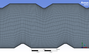
The distribution of the chosen mesh for the two-dimensional flow setup is shown in Figure 3. The structured non-uniform grid was implemented for the enhanced channel walls, characterized by significant refinement in the near-wall regions. This ensures that the dimensionless wall distance (y+) remains within the viscous sub-layer (y+ ≈ 1), providing sufficient resolution to capture the complex flow physics across the entire range of considered Re. The numerical framework was initially validated by replicating the geometry and boundary conditions reported in the experimental study by Elshafei et al. [43]. As shown in Figure 4, the current numerical predictions for the Nu demonstrate strong alignment with the experimental data for (4100 ≤ Re ≤ 9400). To further consolidate the code validation, the Nup and friction fp for the plain smooth channel under turbulent flow were compared against the established correlations of Dittus–Boelter and Blasius [44]. The Dittus–Boelter correlation for heating is given as:
$N u=0.023 R e^{0.8} P r^{0.4}$ (26)
The friction factor was also compared against the Blasius equation:
$f=0.316 R e^{-0.25}$ for $(3000 \leq \operatorname{Re} \leq 20000)$ (27)
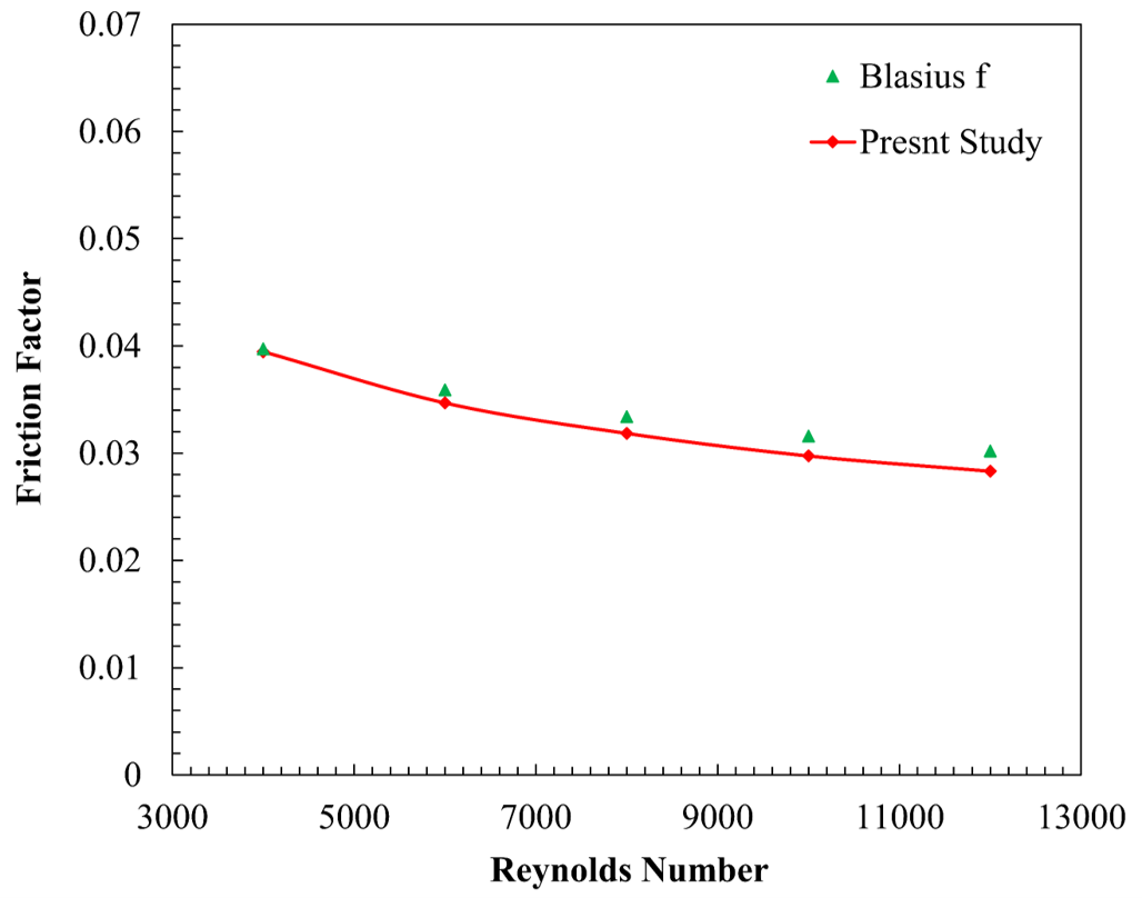
As can be seen in Figures 5 and 6, there is good agreement between the numerical model and empirical correlations (Blasius and Dittus-Boelter, respectively) for which the average deviation is ±3.67% and ±4.07% in fp and Nup, respectively, over the range of Re from 4000 to 10000, which demonstrates reasonable accuracy of the present simulations.
Figure 3. Schematic of grid structure used for the enhanced channel simulation
Figure 4. Validation of current work with experimental study of Elshafei et al. [43]
Figure 5. Numerical model validation through comparison of Nusselt number (Nu) with the Dittus–Boelter correlation
Figure 6. Numerical model validation through comparison of the friction factor with the Blasius correlation
Results from the numerical investigations for assessing the thermal-hydraulic performance of SiO₂-water nanofluid flow through a rectangular channel with trapezoidal obstacles are detailed in this section. Four key parameters are studied, considering nanoparticle volume fraction, diameter and pitch of trapezoidal obstacles and arrangement of obstacles and discussed in terms of thermal performance and flow field. Those four parameters are: (i) arrangement of obstacles: inline and staggered arrays, (ii) nanoparticle volume fraction: 1%, 2%, 3% and 4% vol., (iii) nanoparticle diameter: 20 nm, 30 nm and 40 nm, and (iv) pitch of obstacles: 8 mm, 10 mm and 12 mm. All cases were simulated for Re between 4000 and 10000, which are values that include the turbulent regime observed in real heat exchangers. Evaluation metrics are the Nuav, fav, and TPF.
3.1 The effect of different obstacle arrangement
This section evaluates the thermal-hydraulic performance of the channel at a fixed particle diameter of 30 nm and volume fraction of 4%, comparing the effectiveness of inline versus staggered trapezoidal obstacle arrangements across a Re range of 4000 to 10000. Figure 7. Illustrates that the staggered arrangement provides superior heat transfer performance when compared inline arrangement. The staggered obstacles provide a larger Nu for all tested Re between 4000 ≤ Re ≤ 10000. At Re = 10000, Nu experienced an approximate 9% increase from 128.71 to 140.34 for the staggered arrangement of obstacles. The staggered arrangement outperforms the inline configuration with a mean Nu enhancement of 8.61% across all Re. This superiority is attributed to the staggered geometry forcing the nanofluid into a more tortuous path, which promotes lateral mixing and effectively redevelops the thermal boundary layer more frequently than the inline setup.
Figure 7. Impact of obstacle arrangement on Nusselt number (Nu)
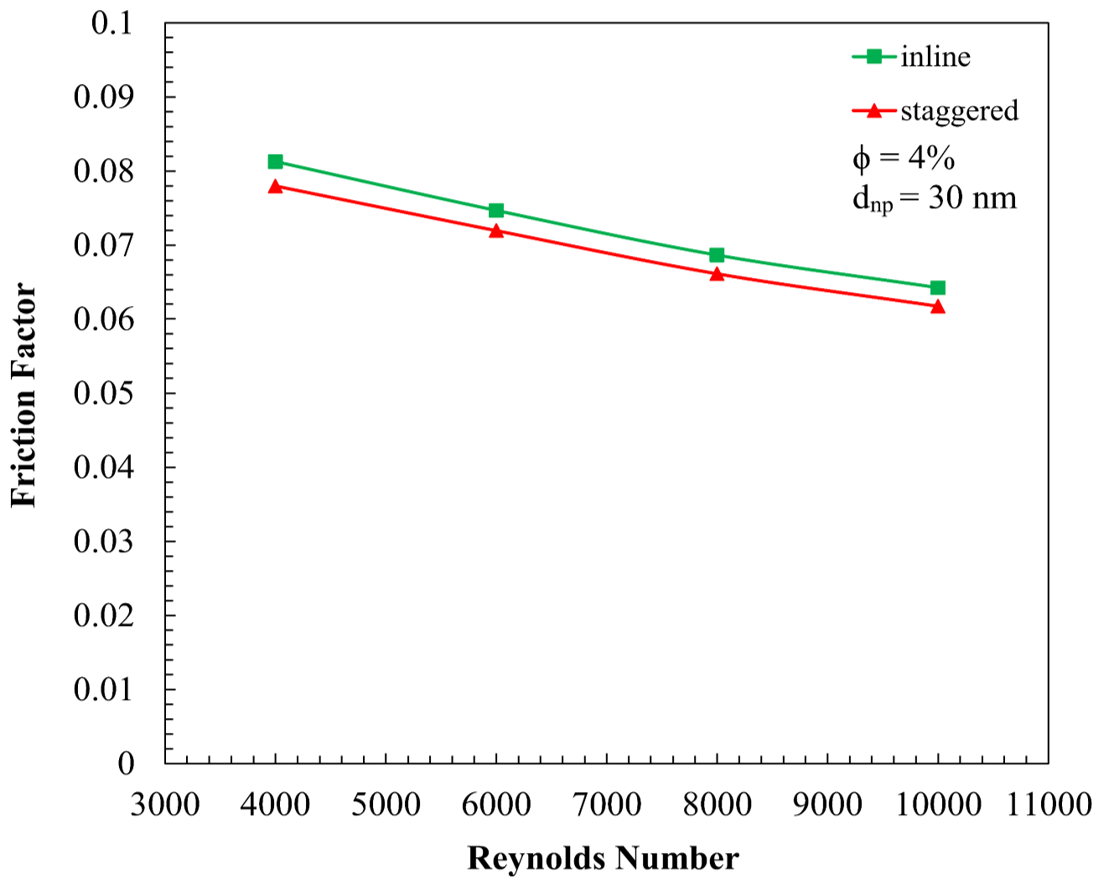
A critical finding is that the staggered arrangement not only enhances heat transfer but also operates with a lower friction factor compared to the inline configuration, as shown in Figure 8. This trend persists throughout all flow regimes. The reduced hydraulic resistance in the staggered arrangement likely stems from the more streamlined flow interaction between successive obstacles, which avoids the massive, high-pressure-drop recirculation zones typically trapped between inline obstacle pairs. Consequently, the staggered arrangement provides increased heat transfer at lower pumping power cost.
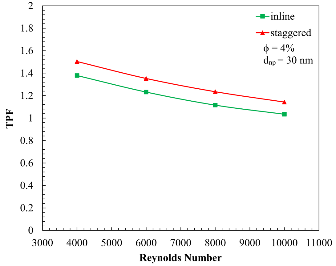
Figure 9 supports the assertion that the staggered arrangement offers superior thermal performance. Since Nu staggered > Nu inline and f staggered < f inline, the resulting TPF for the staggered arrangement is always much greater than unity for any Re. The maximum TPF obtained from this study is 1.504 for the staggered ribs at Re = 4000. Meanwhile, inline obstacles only achieved a TPF of 1.379 at that Re. Though the gap closes at higher turbulence levels, staggered obstacles show a respectable TPF of 1.143 at Re = 10000, whereas inline obstacles approach unity at 1.034. Therefore, the staggered arrangement of trapezoidal obstacles should be used when designing a trapezoidal channel with nanofluids for the best thermal performance.
Figure 8. Impact of obstacle arrangement on friction factor (f)
Figure 9. Impact of obstacle arrangement on thermal performance factor (TPF)
3.2 The effect of nanoparticle volume fractions
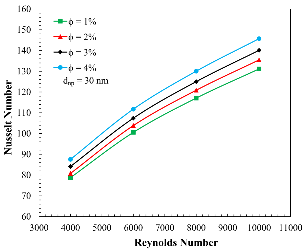
A volume fraction of nanofluid size of 30 nm is considered for staggered arrangement as it showed better thermal performance. Figure 10 reveals a direct proportional relationship between the nanoparticle volume fraction and the Nu. As the volume fraction increases from 1% to 4%, a consistent upward shift in Nu is observed across all Re. An increase in volume fraction from 1% to 4% shows significant thermal improvement for a particle diameter of 30 nm, keeping other parameters constant. At Re = 10000, Nu increases from 131.13 to 145.71, which is a gain of nearly 11.1%. Across all Re, increasing the volume fraction from 1% to 4% provides a consistent mean enhancement of 11.13% in Nu. Such improvement is primarily results from increase in the thermal conductivity of the working fluid at higher volume fraction. Additionally, increased density creates more collisions and vigorous Brownian motion, which helps to thin down the thermal boundary layer near the trapezoidal obstacle surface.
Figure 10. Impact of nanofluid volume fractions on Nusselt number (Nu)
Figure 11. Impact of nanofluid volume fractions on friction factor (f)
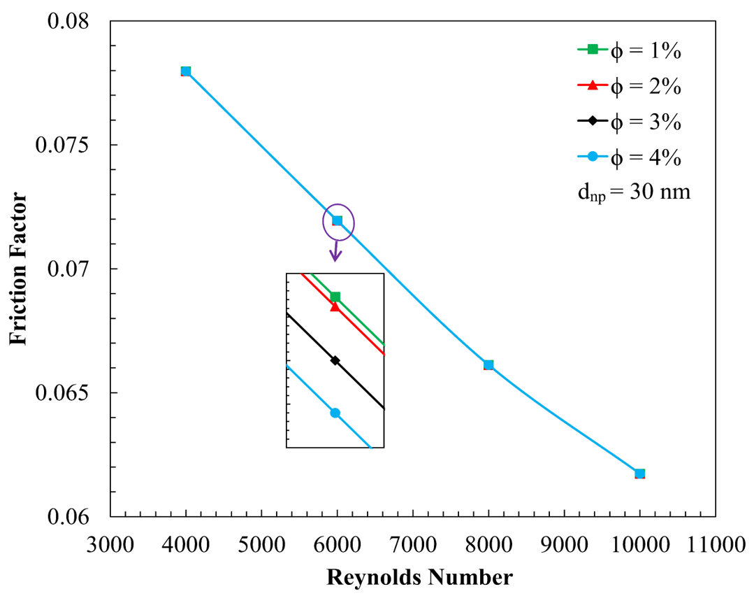
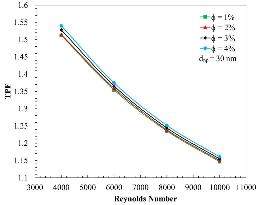
Unlike Nu, f seems to stay steady for all the volume fractions investigated, as depicted in Figure 11. At any Re, f varies negligibly (less than 0.05%) for volume fractions between 1% and 4%. This indicates that for the given range of volume fraction, the increase in viscous dissipation due to nanoparticles gets dominated by form drag and turbulent eddies formed due to trapezoidal obstacles. Thus, the increase in particle loading doesn’t incur a high hydraulic penalty. This outcome implies that an 11.1% Nu increase can be achieved with negligible additional pumping power cost, making this nanofluid volume fraction highly attractive for industrial retrofitting or new designs where energy consumption is a critical factor. Figure 12 demonstrates that since the friction factor remains nearly constant while Nu increases with volume fraction, higher volume fractions consistently deliver superior thermal performance.
The maximum TPF of 1.540 is recorded at Re = 4000 with a 4% volume fraction, whereas the 1% volume fraction yields the lowest TPF of 1.147 at Re = 10000. The steady increase in TPF from 1% through 4% confirms that for the 30 nm nanoparticle size, the highest studied volume fraction (4%) provides the most efficient thermal-hydraulic performance in a trapezoidal-ribbed configuration.
Figure 12. The impact of nanofluid volume fraction on thermal performance factor (TPF)
3.3 The effect of different nanoparticle sizes
Variation of Nu with Re for staggered trapezoidal obstacle arrangement for nanofluid volume fraction of 4% is shown in Figure 13. For all particle sizes considered (dₙₚ = 20, 30, and 40 nm), Nu rises monotonically with Re, which can be explained by stronger turbulent fluctuations at higher Re leading to greater mixing and disruption of the thermal boundary layer by the trapezoidal obstacles. Furthermore, at a given Re value, a decrease in nanoparticle size results in a significant enhancement of the heat transfer rate. In fact, Nu obtained for dₙₚ = 20 nm is about 2.78% and 4.31% higher than the Nu obtained for dₙₚ = 30 nm and dₙₚ = 40 nm, respectively, at Re = 10000. Across all Re, the 20 nm nanoparticles provide a mean enhancement of 4.54% compared to 40 nm particles. This enhancement in heat transfer performance can primarily be explained by two factors: the increase in specific surface area and the intensification of Brownian motion. A reduction in particle size increases the available surface area per unit volume, thereby improving the interaction between the nanoparticles and the base fluid and facilitating more efficient heat transfer. In addition, a reduction in particle size intensifies Brownian motion, leading to greater particle mobility within the fluid. This increased random movement promotes energy transport and continuously generates supplementary pathways for heat flow, thereby enhancing the overall heat transfer performance of the nanofluid. Results obtained for dₙₚ = 30 nm are intermediate values between those obtained for dₙₚ = 20 nm and dₙₚ = 40 nm, confirming consistent degradation of heat transport properties with increase in nanoparticle size within the studied range.
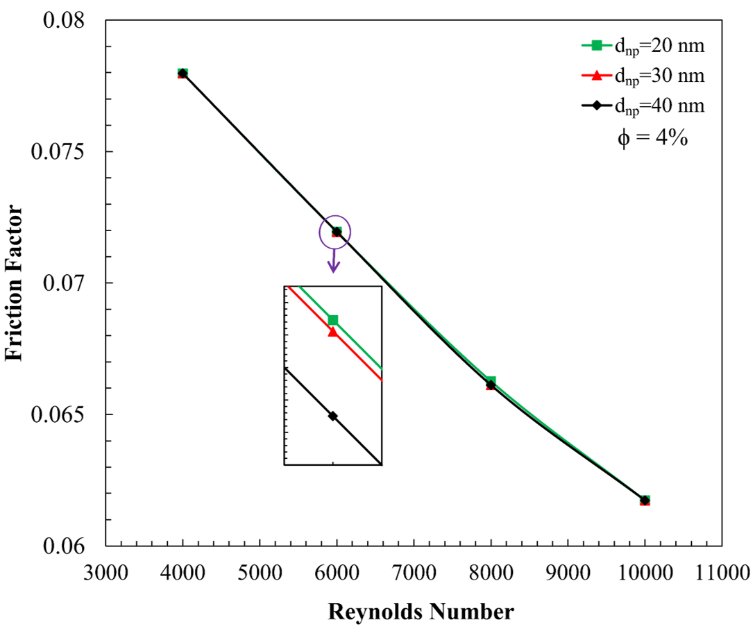
The impact of nanoparticle diameter on the friction factor (f) appears to be statistically marginal, as shown in Figure 14. Across the range of 4000 ≤ Re ≤ 10000, the values of f for all three diameters are nearly identical. This suggests that at a constant volume fraction of 4%, the hydraulic resistance is dominated by the form drag and secondary flow vortices generated by the trapezoidal rib geometry rather than the internal physical dimensions of the suspended nanoparticles. The reduction of f with increasing Re follows the standard trend for turbulent flow in roughened channels, indicating that the use of smaller nanoparticles offers a thermal advantage without any supplemental penalty in pumping power.
Figure 13. The impact of nanoparticle size on Nusselt number (Nu)
Figure 14. The impact of nanoparticle size on the friction factor (f)
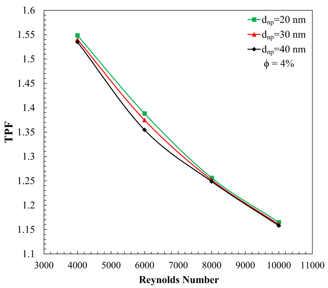
Figure 15 compares the TPF obtained for all cases considered. Values of TPF obtained are all larger than unity, ranging between 1.15 and 1.549, thus confirming observations above that enhancement in heat transfer by use of obstacles and nanofluids is always more than the penalty suffered in the friction factor. Cases using dₙₚ = 20 nm nanoparticles exhibit the highest TPF values, reaching a maximum of 1.549 for the lowest Re value. Nu using dₙₚ = 30 nm nanoparticles settles in between those obtained with dₙₚ = 20 nm and dₙₚ = 40 nm nanoparticles as expected (illustrated with example 1.375 vs. 1.388 for dₙₚ = 20 nm at Re = 6000). Although all values of TPF converge towards each other as Re increases, optimal nanoparticle size remains dₙₚ = 20 nm. The observed trend clearly states that for optimum thermal-hydraulic performance of nanofluid in high performance application with trapezoidal obstacles heat transfer should be enhanced by decreasing nanoparticle size as much as possible.
Figure 15. Impact of nanoparticle size on thermal performance factor (TPF)
3.4 The effect of different obstacle pitches
This section investigates the thermal-hydraulic performance of the trapezoidal-obstacle channel by varying the obstacle pitch (S = 8, 10, and 12 mm) at a constant nanoparticle diameter of 30 nm and a volume fraction of 3% for a staggered arrangement.
The results indicate that the Nu is inversely proportional to the obstacle pitch, as shown in Figure 16. The highest Nu values are recorded for the smallest pitch (S = 8 mm), where the frequency of boundary layer interruption and flow reattachment is greatest. At Re = 10000, the Nu for S = 8 mm is 141.92, which is approximately 6.4% higher than the value of 133.40 observed for S = 12 mm. A smaller pitch promotes more intensive mixing and turbulence near the wall, thereby maximizing the thermal transport capacity of the nanofluid.
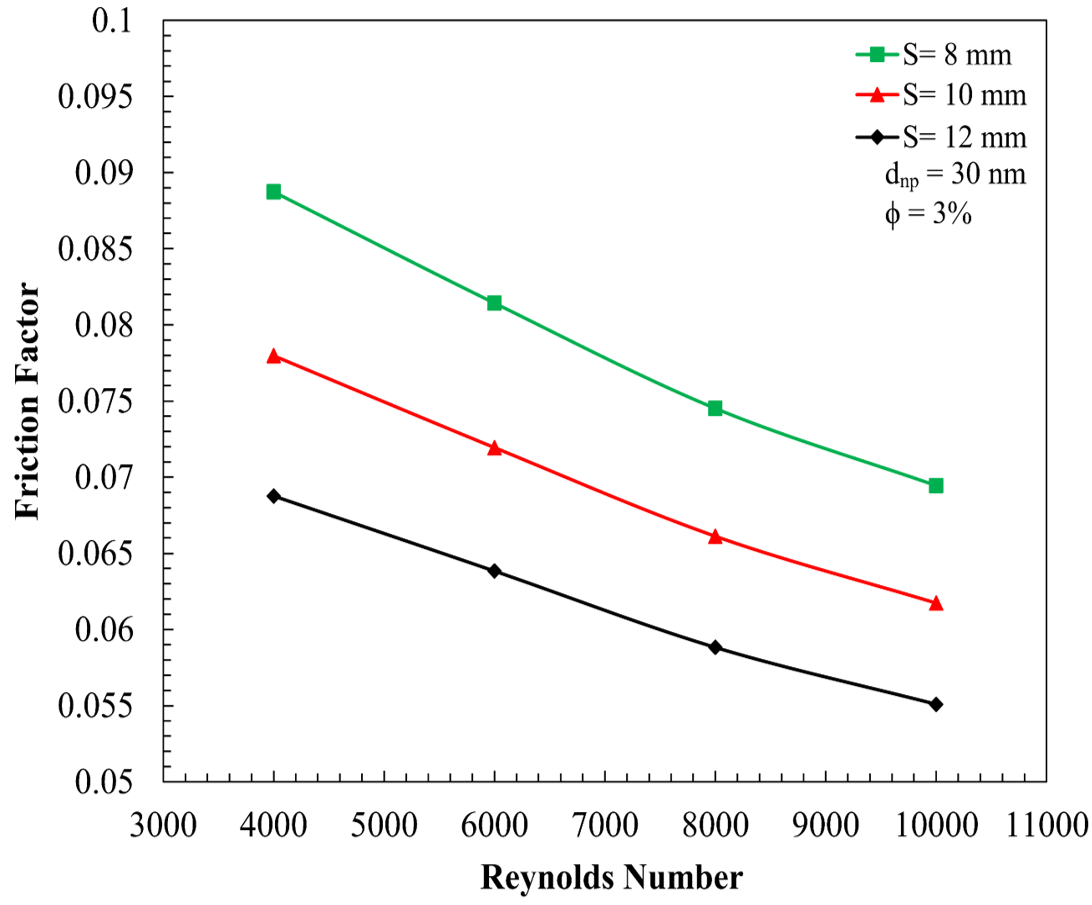
The friction factor increases significantly as the pitch decreases, as shown in Figure 17. The S = 8 mm configuration consistently exhibits the highest hydraulic resistance due to the increased density of trapezoidal obstructions per unit length of the channel. For example, at Re = 4,000, the friction factor for S = 8 mm is approximately 29% higher than that for S = 12 mm.
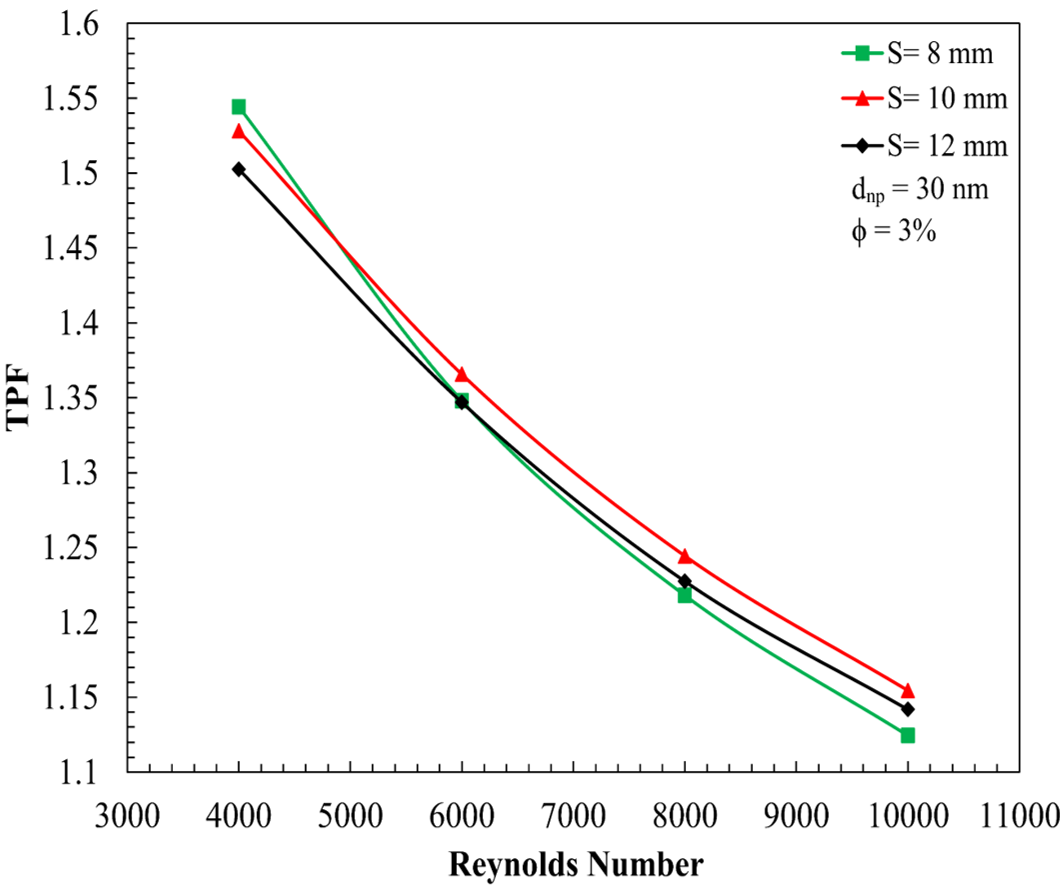
Pitch variation presents a fundamental trade-off: smaller pitch (S = 8 mm) maximizes Nu (6.4% higher than S = 12 mm) but incurs 29% higher friction factor penalty. Larger pitch (S = 12 mm) minimizes the friction factor but reduces heat transfer gains. Figure 18 shows the nonlinear optimization trend of TPF with changing pitch. Maximum TPF at Re = 4000 was achieved with a pitch of 8 mm (TPF = 1.544). However, when considering operation across the entire investigated Re range, S = 10 mm pitch offers superior overall thermal-hydraulic performance, with TPF = 1.155 at Re = 10,000, compared to 1.124 for S = 8 mm and 1.142 for S = 12 mm. This indicates that for Re > 4000, a pitch of 10 mm is the optimal configuration, as heat transfer improvement justifies the penalty incurred by pressure drop. The smaller pitch of 8 mm suffers from an extremely high pressure drop, while the larger pitch of 12 mm does not improve heat transfer as much. Therefore, S = 10 mm is recommended as the optimal geometric configuration for practical operation.
Figure 16. The impact of obstacle pitch on Nusselt number (Nu)
Figure 17. The impact of obstacle pitch on friction factor (f)
Figure 18. The impact of obstacle pitch on thermal performance factor (TPF)
A comprehensive parametric study on thermal-hydraulic performance of SiO2-water nanofluid turbulent flow through a rectangular channel with trapezoidal obstacles was conducted numerically in the present study. Variation in obstacle configuration, nanoparticle volume fraction, nanoparticle diameter, and obstacle pitch over the Re range of (4000 to 10000) has been thoroughly investigated. The following is the conclusion drawn based on the results presented and discussed in the article:
On comparing all the cases considered for parametric study, it can be concluded that maximum value of TPF is achieved for case with staggered arrangement of trapezoidal obstacles, nanoparticle volume fraction of 4%, dnp = 20 nm and pitch of 10 mm. This combination results in TPF of 1.549 at Re = 4000. Within the numerical assumptions adopted in the present study, all investigated cases resulted in TPF values greater than unity, indicating a net thermal-hydraulic advantage of employing SiO2-water nanofluid in a rectangular channel equipped with trapezoidal obstacles for compact heat exchanger applications.
It is important to mention that the present 2D single-phase model does not account for the complexities of the actual 3D turbulent flow or nanoparticle migration phenomena. Validations and further studies with the implementation of 3D simulation and two-phase model will be pursued in future work.
Future investigations should also consider the thermal-hydraulic performance of other nanoparticle materials and hybrid nanofluids within similar obstacle configurations to assess if other materials can yield better or similar thermal-hydraulic performance.
|
A |
cross section area, m2 |
|
Cμ |
turbulence model constant |
|
Cp |
specific heat capacity, J/(kg·K) |
|
Dh |
hydraulic diameter, m |
|
dnp |
nanoparticle diameter, nm |
|
df |
equivalent diameter of a base fluid Molecule |
|
e |
obstacle height, m |
|
f |
friction factor |
|
Gk |
production of turbulent kinetic energy due to mean velocity gradients, kg/(m·s³) |
|
h |
heat transfer coefficient, W/(m²·K) |
|
H |
channel height, m |
|
λ |
thermal conductivity, W/(m·K) |
|
k |
turbulent kinetic energy, (m²/s²) |
|
M |
molecular weight, g/mol |
|
N |
Avogadro number, mol⁻¹ |
|
Nu |
Nusselt number |
|
P |
pressure, N/m² |
|
Pr |
Prandtl number |
|
ΔP |
pressure drop, N/m² |
|
Q |
heat flux, W/m2 |
|
r |
surface geometry function |
|
Re |
Reynolds number |
|
S |
obstacle pitch, m |
|
SiO2 |
silicon dioxide |
|
T |
temperature, K |
|
TPF |
thermal performance factor |
|
u |
flow velocity component, m/s |
|
u' |
velocity fluctuation component, m/s |
|
w |
obstacle width, m |
|
x |
axial coordinate |
|
Greek symbols |
|
|
β |
fraction of the liquid volume that moves along with a nanoparticle |
|
Γ |
molecular thermal diffusivity |
|
Γt |
turbulent thermal diffusivity |
|
ε |
turbulent dissipation rate, $m^2 / s^3$ |
|
Kb |
Boltzmann constant, 1.3807 × 10⁻²³ J/K |
|
μ |
dynamic viscosity, Pa·s |
|
ρ |
density, kg/m3 |
|
ρbf0 |
the mass density of the base fluid calculated at temperature $T_0=293 \mathrm{~K}$ |
|
ϕ |
nanoparticles volume fraction |
|
Subscripts |
|
|
av |
average |
|
b |
bulk |
|
bf |
base fluid |
|
Br |
Brownian |
|
eff |
effect |
|
in |
inlet |
|
i,j |
components |
|
m |
mean |
|
nf |
nanofluid |
|
np |
nanoparticle |
|
out |
outlet |
|
st |
static |
|
t |
turbulent |
|
w |
wall |
[1] Sonawane, S.S., Khedkar, R.S., Wasewar, K.L. (2013). Study on concentric tube heat exchanger heat transfer performance using Al2O3-water based nanofluids. International Communications in Heat and Mass Transfer, 49: 60-68. https://doi.org/10.1016/j.icheatmasstransfer.2013.10.001
[2] Speed, D., Westerhoff, P., Sierra-Alvarez, R., et al. (2015). Physical, chemical, and in vitro toxicological characterization of nanoparticles in chemical mechanical planarization suspensions used in the semiconductor industry: Towards environmental health and safety assessments. Environmental Science: Nano, 2: 227-244. https://doi.org/10.1039/C5EN00046G
[3] Abugnah, E.K., Wan Salim, W.S.I., Elfaghi, A.M. (2023). Impact of geometrical parameters on heat transfer characteristics of SiO2-water nanofluid flow through rectangular corrugated channels. ARFMTS, 104(2): 86-102. https://doi.org/10.37934/arfmts.104.2.86102
[4] Hamood, H.M., Mansour, M.M., Lafta, A.M., Nashee, S.R. (2023). Numerical investigation to study the effect of three height of triangular obstacles on heat transfer of nanofluids in a microchannel. IREME, 17(11): 533-540. https://doi.org/10.15866/ireme.v17i11.23627
[5] Barhdadi, F.Z., Jamal, I., Amghar, K., Daoudi, S. (2025). Numerical simulation of SiO2/water nanofluid heat transfer and turbulent flow in rectangular obstacle channel. Defect and Diffusion Forum, 442: 101-122. https://doi.org/10.4028/p-ILbS1G
[6] Yarmand, H., Gharehkhani, S., Kazi, S.N., Sadeghinezhad, E., Safaei, M.R. (2014). Numerical investigation of heat transfer enhancement in a rectangular heated pipe for turbulent nanofluid. The Scientific World Journal, 2014: 1-9. https://doi.org/10.1155/2014/369593
[7] Ajeel, R.K., Salim, W.S.I., Sopian, K., et al. (2019). Turbulent convective heat transfer of silica oxide nanofluid through corrugated channels: An experimental and numerical study. International Journal of Heat and Mass Transfer, 145: 118806. https://doi.org/10.1016/j.ijheatmasstransfer.2019.118806
[8] Alshukri, M.J., Hamad, R.F., Eidan, A.A., Al-Manea, A. (2024). Convective heat transfer analysis in turbulent nanofluid flow through a rectangular channel with staggered obstacles: A numerical simulation. International Journal of Thermofluids, 23: 100753. https://doi.org/10.1016/j.ijft.2024.100753
[9] Abchouyeh, M.A., Mohebbi, R., Fard, O.S. (2018). Lattice Boltzmann simulation of nanofluid natural convection heat transfer in a channel with a sinusoidal obstacle. International Journal of Modern Physics C, 29(9): 1850079. https://doi.org/10.1142/S0129183118500791
[10] Baghban, A., Sasanipour, J., Pourfayaz, F., et al. (2019). Towards experimental and modeling study of heat transfer performance of water-SiO2 nanofluid in quadrangular cross-section channels. Engineering Applications of Computational Fluid Mechanics, 13(1): 453-469. https://doi.org/10.1080/19942060.2019.1599428
[11] Akbari, O.A., Toghraie, D., Karimipour, A. (2016). Numerical simulation of heat transfer and turbulent flow of water nanofluids copper oxide in rectangular microchannel with semi-attached rib. Advances in Mechanical Engineering, 8(4): 1-25. https://doi.org/10.1177/1687814016641016
[12] Kumar, S., Kumar, A. (2021). A comprehensive review on the heat transfer and nanofluid flow characteristics in different shaped channels. International Journal of Ambient Energy, 42(3): 345-361. https://doi.org/10.1080/01430750.2018.1530139
[13] Esfeh, M.H., Arani, A.A.A., Karimipour, A., Esforjani, S.S.M. (2014). Numerical simulation of natural convection around an obstacle placed in an enclosure filled with different type of nanofluid. Heat Transfer Research, 45(3): 279-292. https://doi.org/10.1615/HeatTransRes.2013007026
[14] Ali, F.A., Alsaffawi, A.M. (2023). Friction factor and heat transfer enhancement of hybrid nanofluids in a heated circular tube. International Journal of Heat and Technology, 41(5): 1383-1388. https://doi.org/10.18280/ijht.410530
[15] Lafta, H.A. (2018). Numerical investigation of flow and heat transfer in a channel with different configurations and alternately order obstacles. University of Thi-Qar Journal, 13(1): 57-73. https://doi.org/10.32792/utq/utj/vol13/1/5
[16] Abedalh, A.S., Shaalan, Z.A., Yassien, H.N.S. (2021). Mixed convective of hybrid nanofluids flow in a backward-facing step. Case Studies in Thermal Engineering, 25: 100868. https://doi.org/10.1016/j.csite.2021.100868
[17] Shaalan, Z.A., Abedalh, A.S., Hamadalla, M.W. (2021). Heat pump performance enhancement by using a nanofluids (experimental study). Journal of Mechanical Engineering Research and Developments, 44(2): 1-9. https://www.scopus.com/pages/publications/85102472702.
[18] Jehad, D.G., Hashim, G.A. (2015). Numerical prediction of forced convective heat transfer and friction factor of turbulent nanofluid flow through straight channels. Journal of Advanced Research in Fluid Mechanics and Thermal Sciences, 8(1): 1-10. https://semarakilmu.com.my/journals/index.php/fluid_mechanics_thermal_sciences/article/view/2543.
[19] Vajjha, R.S., Das, D.K., Kulkarni, D.P. (2010). Development of new correlations for convective heat transfer and friction factor in turbulent regime for nanofluids. International Journal of Heat and Mass Transfer, 53(21-22): 4607-4618. https://doi.org/10.1016/j.ijheatmasstransfer.2010.06.032
[20] Abdullah, B.N., Mohammed, K.H., Soheel, A.H., Ali, B.M., Alomar, O.R. (2025). Analysis of heat transfer inside rectangular micro-channel with wavy surface and hybrid nanofluids. Frontiers in Heat and Mass Transfer, 23(5): 1681-1700. https://doi.org/10.32604/fhmt.2025.066814
[21] Berrehal, H., Sowmya, G. (2021). Heat transfer analysis of nanofluid flow in a channel with non-parallel walls. Journal of Mechanical Science and Technology, 35: 171-177. https://doi.org/10.1007/s12206-020-1216-y
[22] Aghaei, A., Bhattacharyya, S., Dezfulizadeh, A., Goldanlou, A.S., Rostami, S., Sharifpur, M. (2021). Heat transfer and fluid flow analysis using nanofluids in diamond-shaped cavities with novel obstacles. Engineering Applications of Computational Fluid Mechanics, 15(1): 1034-1056. https://doi.org/10.1080/19942060.2021.1930170
[23] Vanaki, S.M., Mohammed, H.A., Abdollahi, A., Wahid, M.A. (2014). Effect of nanoparticle shapes on the heat transfer enhancement in a wavy channel with different phase shifts. Journal of Molecular Liquids, 196: 32-42. https://doi.org/10.1016/j.molliq.2014.03.001
[24] Arani, A.A.A., Sadripour, S., Kermani, S. (2017). Nanoparticle shape effects on thermal-hydraulic performance of boehmite alumina nanofluids in a sinusoidal-wavy mini-channel with phase shift and variable wavelength. International Journal of Mechanical Sciences, 128: 550-563. https://doi.org/10.1016/j.ijmecsci.2017.05.030
[25] Chamkha, A.J., Selimefendigil, F. (2018). Forced convection of pulsating nanofluid flow over a backward facing step with various particle shapes. Energies, 11(11): 3068. https://doi.org/10.3390/en11113068
[26] Yousif, A.A., Alomar, O.R., Hussein, A.T. (2022). Impact of using triple adiabatic obstacles on natural convection inside porous cavity under non-darcy flow and local thermal non-equilibrium model. International Communications in Heat and Mass Transfer, 130: 105760. https://doi.org/10.1016/j.icheatmasstransfer.2021.105760
[27] Markatos, N.C. (1986). The mathematical modelling of turbulent flows. Applied Mathematical Modelling, 10(3): 190-220. https://doi.org/10.1016/0307-904X(86)90045-4
[28] Duarte, J.P., Corradini, M.L. (2018). Hydraulic and heated equivalent diameters used in heat transfer correlations. Nuclear Technology, 201(1): 99-102. https://doi.org/10.1080/00295450.2017.1389594
[29] Saadouni, I., El Mrimar, O., Samoudi, B. (2026). Numerical investigation of nanofluid-filled microchannel heat sinks for improved heat transfer of high-power electronic devices. Journal of Applied Fluid Mechanics, 19(6): 1349-1364. https://doi.org/10.47176/jafm.19.6.4133
[30] Badr, A.A., Luhaibi, M.T., Almula, T.A.D.M.S., Abedalh, A.S. (2026). Thermophysical performance enhancement of vapor-compression chiller systems via metal oxide nanofluid integration. Environmental Progress & Sustainable Energy, 45(1): e70255. https://doi.org/10.1002/ep.70255
[31] Ahsan, M. (2014). Numerical analysis of friction factor for a fully developed turbulent flow using k-ε turbulence model with enhanced wall treatment. Beni-Suef University Journal of Basic and Applied Sciences, 3(4): 269-277. https://doi.org/10.1016/j.bjbas.2014.12.001
[32] Pourfayaz, F., Sanjarian, N., Kasaeian, A., Razi Astaraei, F., Sameti, M., Nasirivatan, S. (2018). An experimental comparison of SiO2/water nanofluid heat transfer in square and circular cross-sectional channels. Journal of Thermal Analysis and Calorimetry, 131: 1577-1586. https://doi.org/10.1007/s10973-017-6500-4
[33] Sahar, A.M., Wissink, J., Mahmoud, M.M., Karayiannis, T.G., Ashrul Ishak, M.S. (2017). Effect of hydraulic diameter and aspect ratio on single phase flow and heat transfer in a rectangular microchannel. Applied Thermal Engineering, 115: 793-814. https://doi.org/10.1016/j.applthermaleng.2017.01.018
[34] Manca, O., Nardini, S., Ricci, D. (2012). A numerical study of nanofluid forced convection in ribbed channels. Applied Thermal Engineering, 37: 280-292. https://doi.org/10.1016/j.applthermaleng.2011.11.030
[35] Thejaraju, R., Girisha, K., Manjunath, S., Dayananda, B. (2020). Numerical evaluation of thermo-hydraulic performance index of a double pipe heat exchanger using double sided louvered winglet tape. Journal of Thermal Engineering, 6(5): 843-857. https://doi.org/10.18186/thermal.800267
[36] Heidary, H., Kermani, M.J. (2010). Effect of nano-particles on forced convection in sinusoidal-wall channel. International Communications in Heat and Mass Transfer, 37(10): 1520-1527. https://doi.org/10.1016/j.icheatmasstransfer.2010.08.018
[37] Idan Al-Chlaihawi, K.K., Alyas, B.H., Badr, A.A. (2023). CFD based numerical performance assessment of a solar air heater duct roughened by transverse - trapezoidal sectioned ribs. International Journal of Heat and Technology, 41(5): 1273-1281. https://doi.org/10.18280/ijht.410517
[38] Murshed, S.M.S. (2011). Determination of effective specific heat of nanofluids. Journal of Experimental Nanoscience, 6(5): 539-546. https://doi.org/10.1080/17458080.2010.498838
[39] Kalsi, S., Kumar, S., Kumar, A., Alam, T., Dobrotă, D. (2023). Thermophysical properties of nanofluids and their potential applications in heat transfer enhancement: A review. Arabian Journal of Chemistry, 16(11): 105272. https://doi.org/10.1016/j.arabjc.2023.105272
[40] Corcione, M. (2011). Empirical correlating equations for predicting the effective thermal conductivity and dynamic viscosity of nanofluids. Energy Conversion and Management, 52(1): 789-793. https://doi.org/10.1016/j.enconman.2010.06.072
[41] Lienhard IV, J.H., Lienhard V, J.H. (2017). A Heat Transfer Textbook, 4th ed. Phlogiston Press, Cambridge, MA.
[42] Incropera, F.P., DeWitt, D.P., Bergman, T.L., Lavine, A.S. (2007). Fundamentals of Heat and Mass Transfer, 6th ed. Wiley, Hoboken, NJ.
[43] Elshafei, E.A.M., Awad, M.M., El-Negiry, E., Ali, A.G. (2010). Heat transfer and pressure drop in corrugated channels. Energy, 35(1): 101-110. https://doi.org/10.1016/j.energy.2009.08.031
[44] Kreith, F., Manglik, R.M., Bohn, M.S. (2011). Principles of Heat Transfer, 7th ed. Cengage Learning, Stamford, CT.