Arati Arvind Waghmare | Sanjay Kantrao Kulkarni*
© 2026 The authors. This article is published by IIETA and is licensed under the CC BY 4.0 license (http://creativecommons.org/licenses/by/4.0/).
OPEN ACCESS
This work examines the thermal response of symmetric sandwich beams composed of a three-layer (0°/core/0°) configuration under localized thermal actions in the form of a thermal point load, thermal line load and thermal patch load. In the present work, the term “quasi-3D” refers to higher-order beam models in which the transverse strain (εz ≠ 0) is included within a one-dimensional beam formulation through an enriched displacement field. The formulation captures transverse normal deformation and improved through-thickness stress variation, while retaining the computational simplicity of beam theory and not representing a complete three-dimensional thermoelastic analysis. The influence of transverse normal strain (εz ≠ 0) is incorporated in the displacement field of trigonometric shear deformation theory (TSDT) and parabolic shear deformation theory (PSDT) to enhance accuracy. The novelty of this work lies in the application of these quasi-3D theories to sandwich beams under localized thermal point, line and patch loads, which has received limited attention in earlier research work. Thermal deformations and stresses corresponding to different aspect ratios are analyzed using the principle of virtual work in conjunction with Navier’s method. A script with the help of MATLAB software has been developed to generate the output efficiently across a range of aspect ratios. The results reveal that TSDT consistently predicts higher stress magnitudes and displacements under thermal loads. It is also noted that Timoshenko beam theory (also known as first-order shear deformation theory (FSDT)) offers computational efficiency with acceptable accuracy for higher values of aspect ratios. The convergence of results at high values of aspect ratio validates the applicability of simplified refined models. This comparative framework provides practical insights for selecting appropriate theories in thermal design of composite sandwich structures.
sandwich beam, thermal patch load, thermal line load, thermal point load, higher-order theories
Modern engineering increasingly uses laminated and sandwich structures because of their sustainability and attractive mechanical properties. These materials, when used in space structures such as rockets and satellites, are often subjected to high temperatures. Hence, the performance of sandwich beams in a thermal atmosphere requires careful investigation.
A sandwich beam comprises two or more thin, stiff outer layers and a thick central core. Due to this variation in its cross-section, rigidity is developed. Therefore, to achieve refinement in the modeling of sandwich beams, it is necessary to assess the interlaminar shear and normal stresses more accurately. Further, the beam may be subjected to thermal loads concentrated at a particular point or may be spread over a particular area in the form of a patch. Being the basic and important part of any machine or structure, capturing the exact behaviour of a sandwich beam under a variety of thermal loading is of utmost importance.
In a practical situation, sandwich beams may experience localized heating such as thermal point heating, line heating or heating over a small portion. Such loads may create complex deformation patterns inside the sandwich structure. However, the effect of localized thermal loading on sandwich beam, along with the transverse normal effect, has not been widely investigated in the literature.
This work aims to analyze the thermal response of a symmetric sandwich layered beam subjected to centralized thermal point, line, and patch loads, using a refined quasi-3D beam theory that incorporates the transverse normal strain effect. The study further compares different shear deformation theories to assess their capability in predicting thermal stresses and displacements in sandwich beams.
Earlier investigations into sandwich beams subjected to thermal and mechanical loading can be generally grouped into three categories: (i) refined and higher-order theories for sandwich structures, (ii) thermoelastic and thermal deformation models and (iii) studies on thermal loading and advanced applications of sandwich systems. The important contributions related to the present study are summarized below.
The first category deals with the development of refined kinematic theories for the accurate prediction of stresses and deformations in sandwich structures. Carrera and Brischetto [1] presented a comprehensive assessment of classical and advanced theories for sandwich plates and demonstrated the advantages of refined formulations over conventional models. Phan et al. [2] proposed an extended higher-order theory suitable for sandwich beams with compliant cores by considering axial and transverse deformation effects. Nguyen et al. [3] introduced a quasi-3D shear deformation theory incorporating transverse normal strain in sandwich beam analysis. Sayyad and Naik [4] later developed a refined displacement model capable of predicting transverse shear stresses more accurately in laminated and sandwich plates. Belarbi et al. [5] proposed a three-unknown refined shear deformation model for curved sandwich beams containing functionally graded layers. Carrera [6] emphasized the necessity of considering transverse normal strain effects in thermoelastic analysis of layered structures to improve accuracy. Sayyad et al. [7] introduced a refined trigonometric beam theory that predicts stresses and deflections efficiently without using shear correction factors. These investigations collectively demonstrated that higher-order and quasi-3D theories are more reliable for analyzing thick sandwich members and layered composites.
The second category of literature mainly focuses on thermoelastic analysis of laminated, sandwich and functionally graded members. Zenkour and Alghamdi [8] investigated the thermo-mechanical bending behaviour of functionally graded sandwich plates subjected to combined loading. Ebrahimi and Farazmandnia [9] studied thermo-mechanical vibration response of carbon nanotube reinforced sandwich beams using higher-order theory. Daikh and Megueni [10] examined thermal buckling characteristics of functionally graded sandwich plates under elevated temperature conditions. Swaminathan and Sangeetha [11] reviewed different modelling approaches available for thermal analysis of functionally graded plates. Naik and Sayyad [12] developed a quasi-3D computational model for thermal analysis of laminated and sandwich plates considering transverse shear and normal deformation effects. Singh and Harsha [13] proposed a higher-order theory for thermo-mechanical analysis of porous sandwich plates with different boundary conditions. Cho [14] investigated the thermoelastic behaviour of sandwich plates with homogeneous cores through a two-dimensional numerical formulation, whereas Houari et al. [15] analyzed the thermal bending response of thick sandwich plates including transverse stretching effects. Kulkarni [16] also investigated transverse thermal displacements in symmetric beams using a higher-order shear deformation approach. These contributions indicate that thermal loading significantly affects the behaviour of sandwich structures and requires refined modelling for accurate prediction.
The third group of studies deals with advanced applications of sandwich structures under different thermal and mechanical environments. Arikoglu and Ozkol [17] analyzed the vibration characteristics of viscoelastic sandwich beams, while Arvin et al. [18] investigated free and forced vibration response using higher-order finite element formulations. Lou et al. [19] studied the vibration behaviour of sandwich beams having lattice truss cores. Bui et al. [20] employed a mesh-free radial point interpolation technique for the dynamic analysis of functionally graded sandwich beams. Wu et al. [21] performed vibration and buckling analysis of carbon nanotube-reinforced sandwich beams. Yan et al. [22] experimentally examined steel-concrete-steel sandwich beams for structural applications. Sayyad and Ghugal [23, 24] presented comprehensive review articles on laminated composite and functionally graded sandwich beams. Lin et al. [25] conducted experimental and finite element analysis of sandwich beams with layered gradient foam cores under low velocity impact. Kulkarni and Ghugal [26] obtained closed-form thermo-elastic solutions for laminated composite and sandwich beams subjected to thermal loading. Onyibo and Safaei [27] reviewed finite element applications to honeycomb sandwich structures. Lu et al. [28] developed an active vibration control system for piezoelectric sandwich beams.
The above review indicates that substantial progress has been achieved in modelling and thermal/mechanical analysis of sandwich structures. Nevertheless, only limited studies have focused on analytical prediction of transverse thermal response in sandwich beams while simultaneously incorporating higher-order shear deformation and transverse normal strain effects within a computationally efficient framework.
The present work, therefore, develops a refined higher-order model that includes transverse normal strain for sandwich beams subjected to thermal point, line and patch loading.
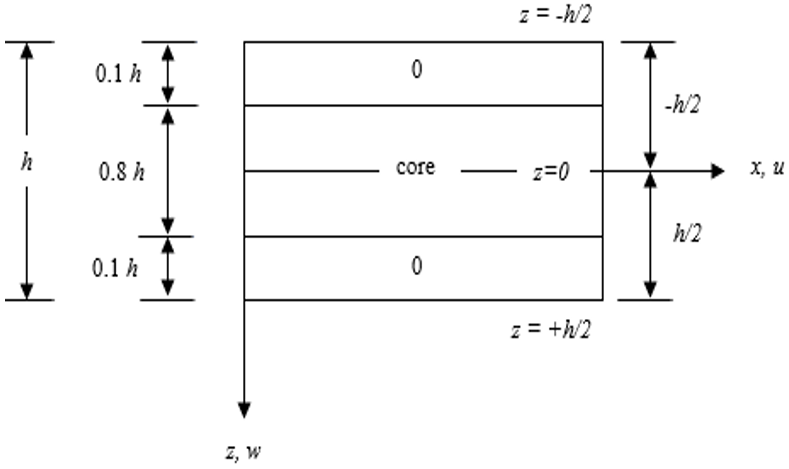
The sandwich beam consists of two identical face sheets and a lightweight core placed between them. This configuration or arrangement is commonly represented by (0°/core/0°). The face sheets are oriented in the same directions, i.e., the fibers in the face sheets are parallel to the x-axis. The angle between fibers and the x-axis is zero; this is called a zero-degree thin laminated face sheet. The soft core mainly resists shear and increases the overall thickness of the sandwich beam. The total thickness of sandwich beam is represented by h. The thickness of each face sheet is considered as 0.1 h. The thickness of the soft core is considered to be 0.8 h, as shown in Figure 1. Such a form of a structure improves stiffness without increasing the weight of the structure. The geometric arrangement or stacking sequence of the three-layer sandwich beam considered in the present study is shown in Figure 1.
Figure 1. The cross-section of sandwich beam with the position of the x and z axes
2.1 The displacement fields of trigonometric and parabolic shear deformation theory
The present trigonometric and parabolic theories are refined one-dimensional beam formulations incorporating transverse normal strain effects $\left(\varepsilon_z \neq 0\right)$ through the displacement field without employing a complete three-dimensional thermoelastic model, and are therefore termed quasi-3D theories.
The trigonometric shear deformation theory (TSDT) is an advanced structural analysis approach used in structural mechanics for studying layered sandwich beam structures. In TSDT, a sinusoidal function is adopted in the equation of displacement, which makes the kinematics of this theory better. This theory bridges the gap between simple beam theories and three-dimensional elasticity solutions.
This makes the theory very effective for engineering applications involving layered sandwich structures. The kinematics of this theory are represented by Eqs. (1) and (2).
$u(x, z)=u_0(x)-z \frac{\partial w}{\partial x}+\frac{h}{\pi} \sin \frac{\pi z}{h} \varphi(x)$ (1)
$w(x, z)=w_0(x)+\cos \frac{\pi z}{h} \xi(x)$ (2)
The parabolic shear deformation theory (PSDT) is a refined theory used to analyze layered sandwich structures. It assumes a parabolic distribution of transverse shear strain through the thickness of the sandwich beam. This reflects more closely the actual physical behaviour of the sandwich beam structure. The displacement field or kinematics of this theory is represented by Eqs. (3) and (4).
$u=u_0(x)-z \frac{\partial w}{\partial x}+z\left(1-\frac{4 z^2}{3 h^2}\right) \varphi(x)$ (3)
$w(x, z)=w_0(x)+\left(1-\frac{4 z^2}{h^2}\right) \xi(x)$ (4)
where, $u$ and $w$ are the displacements in $x$ and $z$ direction respectively. $u_0$ and $w_0$ are the displacements along the center-line and $\varphi(x)$ and $\xi(x)$ are the rotational components at the mid-plane.
2.2 Temperature field
In this work, thermal loads are defined as prescribed temperature boundary conditions rather than heat fluxes or internal heat sources. A point thermal load corresponds to a sharply localized prescribed temperature rise at the beam center, a line thermal load represents a narrow strip of elevated temperature along the mid-span and a patch thermal load corresponds to a finite heated region at the center. These idealizations are used to study localized thermal gradients in a controlled manner. The quantities $T_0(x), \,\, T_1(x)$ and $T(x, z)$ in Eq. (5) represent prescribed temperature rises relative to the reference temperature $T_{\text {ref}}$. These temperature differences are expressed in Kelvin (K) or equivalently in degrees Celsius (℃), since only temperature increments are involved in the thermoelastic analysis.
The linear variation of temperature through the thickness of the sandwich beam structure is represented by the following Eq. (5).
$T(x, z)=T_0(x)+\frac{2 z}{h} T_1(x)$ (5)
The mid-plane temperature component $T_0(x)$ is defined as a piecewise continuous function along the beam axis, representing the average temperature at the mid-surface. For example, under thermal patch load, $T_0(x)$ is constant within the heated region and zero outside. The Fourier expansion of $T_0(x)$ is used for mathematical representation, but physically it corresponds to a prescribed temperature distribution. The term $T_1(x)$ introduces the thickness-dependent variation and represents the difference between the top and bottom surface temperatures relative to the mid-plane. If both surfaces are at the same temperature, $T_1(x)=0$. The assumed linear through-thickness distribution is a first-order approximation widely adopted in quasi-3D or TSDT. It captures the dominant gradient between the top and bottom surfaces while allowing axial variation along $x$. Although higher-order distributions may be required for thin-walled structures under highly localized heating, the linear assumption provides a balance between physical realism and analytical tractability.
Another term in the expression, $\frac{2 z}{h} T_1(x)$ is thickness-dependent variation where z is the distance from the mid-plane and h is the total thickness of the sandwich beam.
This formulation ensures that temperature changes are captured both along the beam length (x) and across its thickness direction (z). This type of temperature field is often applied in advanced beam theories to model realistic thermal gradients without oversimplifying the distribution.
2.3 Development of strains and stresses
The strain in $x$ and $z$ directions is derived from the basics of solid mechanics. The strain in $x$ direction $\left(\varepsilon_x\right)$, is derived from the displacement $(u)$. It includes mid-plane displacement gradient $\left(\frac{\partial u_0}{\partial x}\right)$, bending curvature $\left(z \frac{\partial^2 w}{\partial x^2}\right)$ and a higher-order term $\left(sin \frac{\pi z}{h}\right)$ which accounts for shear deformation effect through ($\varphi$) as represented by Eq. (6). The strain in $z$ direction $\left(\varepsilon_z\right)$, comes from the derivative of transverse displacement ($w$) with respect to the thickness direction. The sinusoidal term $\left(sin \frac{\pi z}{h} \xi\right)$ reflects how the thickness strain is distributed across the depth of the beam. This is represented by Eq. (7). The shear strain $\left(\gamma_{z x}\right)$ combines the variation of displacement $u$ with respect to $z$ and transverse displacement $w$ with respect to $x$ representing the distortion due to angular changes between axes, represented by Eq. (8).
$\varepsilon_x=\frac{\partial u}{\partial x}=\frac{\partial u_0}{\partial x}-z \frac{\partial^2 w}{\partial x^2}+\frac{h}{\pi}\left(sin \frac{\pi z}{h}\right) \frac{\partial \varphi}{\partial x}$ (6)
$\varepsilon_z=\frac{\partial w}{\partial z}=-\frac{h}{\pi} sin \frac{\pi z}{h} \xi(x)$ (7)
$\gamma_{z x}=\frac{\partial u}{\partial z}+\frac{\partial w}{\partial x}=-\frac{\partial w_0}{\partial x}+cos \left(\frac{\pi z}{h}\right) \frac{\partial \xi}{\partial x}+\varphi(x)$ (8)
For the $k^{\text {th}}$ layer, the normal stress $\left(\sigma_x\right)$ and transverse stress $\sigma_z$ in terms of the reduced thickness $\bar{Q}_{i j}^{(k)}$ and elastic constants are given by Eq. (9).
$\left[\begin{array}{c} \sigma_x \\ \sigma_z \\ \tau_{x z} \end{array}\right]=\left[\begin{array}{ccc} \bar{Q}_{11} & \bar{Q}_{13} & 0 \\ \bar{Q}_{13} & \bar{Q}_{33} & 0 \\ 0 & 0 & \bar{Q}_{55} \end{array}\right]\left\{\begin{array}{c} \varepsilon_x-\alpha_x T \\ \varepsilon_z-\alpha_z T \\ \gamma_{x z} \end{array}\right\}$ (9)
$\bar{Q}_{11}^{(k)}=\frac{\bar{E}_1^{(k)}}{\left(1-\mu_{13}(k) \mu_{31}(k)\right)}$ (10)
$\bar{Q}_{13}^{(k)}=\frac{\mu_{13}(k) \bar{E}_1^{(k)}}{\left(1-\mu_{13}(k) \mu_{31}(k)\right)}$ (11)
$\bar{Q}_{33}^{(k)}=\frac{\bar{E}_3^{(k)}}{\left(1-\mu_{13}(k) \mu_{31}(k)\right)}$ (12)
In the above expressions, $\mu_{i j}$ is the Poisson's ratio and $\alpha_x, \alpha_z$ are the coefficients of thermal expansion in $x$ and $z$ directions, respectively. Subscript 1 and 3 indicates $x$ and $z$ directions.
2.4 Application of virtual work principle
The principle of virtual work is a fundamental concept in elasticity or structural mechanics that provides a powerful way to derive governing equations for a structural element or a structural member. When this principle is applied to a sandwich beam, the formulation becomes particularly useful because such beams are composed of multiple layers with different material properties. This principle, when applied to sandwich beam, can be stated in the following form and represented by Eq. (13).
$\int_{z=-h / 2}^{z=+h / 2} \int_{x=0}^{x=a}\left(\sigma_X \delta \varepsilon_X+\sigma_z \delta \varepsilon_z+\tau_{z X} \delta \gamma_{z X}\right) d x d z=0$ (13)
The above equation was simplified using integration by parts. The symbols $\delta u_0, \delta w, \delta \varphi, \delta \xi$ denote the virtual variations corresponding to the axial displacement $u_0$, transverse displacement $w$, rotation $\varphi$ and higher-order variable $\xi$ respectively. By collecting the coefficients of these independent virtual variations and setting them equal to zero, the governing equations of TSDT formulation are obtained and presented in Eqs. (14a)-(14c).
2.4.1 Definition of stiffness coefficients
To establish clarity in the governing equations, all stiffness coefficients used in the governing Eq. (14) are defined here in this section. The coefficients arise from the layer-wise integration of the reduced stiffness matrix $\bar{Q}_{i j}^{(k)}$ across thickness of the sandwich beam. The classical terms such as $A_{i j}, B_{i j}, D_{i j}$ represent extensional, coupling and bending stiffnesses, while additional coefficients $S A_{i j}, S B_{i j}, S S_{i j}, T B_{i j}, C C_{55}$ originate from higher-order displacement assumptions and thermo-elastic coupling. The following classification is adopted throughout the paper.
$A_{i j}, B_{i j}, D_{i j}$: Classical extensional, coupling and bending stiffness.
$S A_{i j}, S B_{i j}, S S_{i j}, T B_{i j}, C C_{55}$: Higher-order stiffness terms arising from sinusoidal functions in the assumed displacement field.
$T B_{i j}, T D_{i j}, T S A_{i j}, T S B_{i j}$: These are thermo-elastic stiffnesses, incorporating the thermal expansion coefficient $\alpha_x$.
$C C_{55}$: This is shear correction stiffness.
The explicit integral forms of these coefficients are given in Eqs. (15)-(18).
With these definitions in place, the governing equations of motion can now be expressed in terms of the stiffness coefficients as shown in the following Eq. (14a). The governing equations can be written in matrix form as given below.
The unknown vectors are defined as follows:
$q(x)=\left[\begin{array}{l} u_0(x) \\ w(x) \\ \varphi(x) \\ \xi(x) \end{array}\right]$ (14a)
$k(\partial x)=\left[\begin{array}{cccc} -A_{11} \partial_x^2 & B_{11} \partial_x^3 & -\frac{S A_{11} h}{\pi} \partial_x^2 & \frac{S A_{13} \pi}{h} \partial_x \\ -B_{11} \partial_x^3 & D_{11} \partial_x^4 & -\frac{S B_{11} h}{\pi} \partial_x^3 & \frac{\pi}{h} S B_{13} \partial_x^2 \\ -\frac{h}{\pi} A_{11} \partial_x^2 & \frac{h}{\pi} B_{11} \partial_x^3 & -\frac{S S_{11} h^2}{\pi^2} \partial_x^2+C C_{55} & S S_{13} \partial_x+C C_{55} \partial_x \\ -\frac{\pi}{h} A_{11} \partial_x & -\frac{\pi}{h} B_{11} \partial_x^2 & -\left(S S_{13}+C C_{55}\right) \partial_x & -C C_{55} \partial_x^2+\frac{\pi^2}{h^2} S S_{33} \end{array}\right]$ (14b)
$f(x)=\left[\begin{array}{c} \partial_x T_0\left(T A_{11}+T A_{13}\right)+\frac{2}{h} \partial_x T_1\left(T B_{11}+T B_{13}\right) \\ \partial_x^2 T_0\left(T B_{11}+T B_{13}\right)+\frac{2}{h} \partial_x^2 T_1\left(T D_{11}+T D_{13}\right) \\ \frac{h}{\pi} \partial_x T_0\left(T S A_{11}+T S A_{13}\right)+\frac{2}{\pi} \partial_x T_1\left(T S B_{11}+T S B_{13}\right) \\ \frac{\pi}{h} T_0\left(T S A_{12}+T S A_{33}\right)+\frac{2 \pi^2 T_1}{h^2}\left(T S B_{12}+T S B_{33}\right) \end{array}\right]$ (14c)
Each governing equation can be expressed as a linear combination of derivatives of $q(x)$ and assembling these into a differential operator matrix acting on $q(x)$. The coupled governing equations can be expressed compactly in operator matrix form as $k(\partial x) q(x)=f(x)$, where $f(x)$ collects the thermal load terms i.e right hand side contributions from $T_0, T_1$. The operator matrix $k(\partial x)$ and the right-hand side matrix $f(x)$ are shown in Eqs. (14b) and (14c). The term $\partial_x$ equals to $\frac{\partial}{\partial x}$ in the above equations.
2.4.2 General nondimensionalization framework
For clarity and to facilitate parametric studies, the governing equations are expressed in nondimensional form. The spatial coordinate is scaled as $\bar{x}=x / L$, where $L$ or $a$ is the characteristic length. Displacements are normalized by sandwich beam thickness $\bar{u}_0=u_0 / h$ and $\bar{w}=w / h$, while the shear variable is scaled as $\xi=\xi / h$. The rotation variable $\varphi$ is inherently nondimensional. The temperature fields are normalized with respect to a reference temperature, $\bar{T}_0= T_0 / T_{\text {ref}}$ and $\bar{T}_1=T_1 / T_{\text {ref}}$. This nondimensionalization reduces the operator matrix to a form governed by dimensionless parameters, allowing results to be interpreted independently of specific geometric or thermal scale.
The above nondimensional variables are introduced to obtain the dimensionless form of governing equations and associated boundary conditions. For the presentation of the numerical results, additional response-specific normalization factors are employed to facilitate comparison of displacements and stresses under different thermal loading conditions. Accordingly, the dimensionless response quantities reported in Section 3.1 are defined using Eqs. (22a)-(22d), where the characteristic thermal quantity $\alpha_L T_1$ and the beam length a is adopted as a reference scale. Thus, the nondimensionalization described in the present section provides the general mathematical framework, whereas the response normalizations introduced in Section 3.1 are used specifically for reporting numerical results.
2.4.3 Implementation
The nondimensional governing system was implemented in MATLAB. The unknown vector was expanded using truncated series representations, and the operator matrix was assembled into discrete algebraic form. A truncation order of m = 25 terms was adopted to balance accuracy and computational efficiency. The resulting system was solved using MATLAB’s built-in solver. The convergence was verified by increasing the truncation order and comparing successive results for displacement and stress fields. When the relative change between successive truncation levels fell below 1%, the solution was considered converged. This procedure ensures that the reported results are numerically stable and independent of truncation order.
In Eq. (14), the stiffness coefficients $A_{i j}, B_{i j}$ and $D_{i j}$ are defined as:
$A_{11}, B_{11}, D_{11}=\sum_{k=1}^N \int_{z=k}^{k+1} \bar{Q}_{11}^{(k)}\left(1, z, z^2\right) d z$ (15)
$S A_{11}, S B_{11}, S S_{11}=\sum_{k=1}^N \int_{z=k}^{k+1} \bar{Q}_{11}^{(k)} \frac{h}{\pi}\left(\sin \frac{\pi z}{h}\right)\left(1, z, \frac{h}{\pi}\left(\sin \frac{\pi z}{h}\right)\right) d z$ (16)
$T B_{11}, T D_{11}, T S A_{11}, T S B_{11}=\sum_{k=1}^N\left(\alpha_x\right) \int_{z=k}^{k+1} \bar{Q}_{11}^{(k)}\left(z, z^2, \sin \frac{\pi z}{h}, \sin ^2\left(\frac{\pi z}{h}\right)\right) d z$ (17)
$C C_{55}=\sum_{k=1}^N \int_{z=k}^{k+1} \bar{Q}_{55}^{(k)} \cos ^2\left(\frac{\pi z}{h}\right) d z$ (18)
For a symmetric sandwich beam, $B_{11}, T B_{11}, S A_{11}=0$, due to mid-plane symmetry. The term $u_0=0$ because the simply supported ends restrain axial displacement in the $x$ direction, eliminating in-plane extension at the supports. This symmetry and boundary enforcement lead directly to Eq. (19) as given below.
$B_{11}, T B_{11}, S A_{11}=0 \text { and } u_0=0$ (19)
2.4.4 Boundary conditions for simply supported ends
For the present sandwich beam, the following boundary conditions (Table 1) are applied at $x=0$ and $x=a$.
Table 1. Boundary conditions for simply supported ends
|
Variables |
Boundary Condition |
Physical Meaning |
|
$u_0$ |
$u_0=0$ |
Axial displacement restrained |
|
$w_0$ |
$w_0=0$ |
No transverse deflection at supports |
|
$\varphi$ |
$\varphi=0$ |
Rotation vanishes at supports |
|
$\xi$ |
$\xi=0$ |
Higher-order warping vanishes |
|
$M_x, N_x, M_x^s$ |
$M_x, N_x, M_x^s=0$ |
Bending moment, axial force and support moment vanish |
2.4.5 Justification of sine/cosine expansion
Sine series are used for variables that must vanish at simply supported ends $\left(w_0, \xi, T_0, T_1\right)$. The cosine series is used for variables with symmetric distributions or a zero slope at supports $\left(u_0, \varphi\right)$. This choice ensures automatic satisfaction of boundary conditions and orthogonality in Navier's method.
2.5 Solution of governing equations
The beam under consideration has simple supports at its ends; hence, it will have zero deflection $(w=0)$ at its ends. Similarly, bending moment, support moment and in-plane normal force in $x$ direction will also cease to zero at both ends ($M_x=0, N_x=0, M_x^s=0$). Navier's technique is adopted to solve the governing equations. This technique uses solutions in the following Fourier trigonometric forms.
$\left[\begin{array}{l} u_0 \\ w_0 \\ \varphi_0 \\ \xi_0 \\ T_0 \\ T_1 \end{array}\right]=\sum_{m=1}^{\infty}\left[\begin{array}{l} u_m cos \frac{m \pi x}{a} \\ w_m sin \frac{m \pi x}{a} \\ \varphi_m cos \frac{m \pi x}{a} \\ \xi_m sin \frac{m \pi x}{a} \\ T_{0 m} sin \frac{m \pi x}{a} \\ T_{1 m} sin \frac{m \pi x}{a} \end{array}\right]$ (20)
where,
$T_{0 m}=T_0, \mathrm{~m}=1$ for sinusoidal thermal loading.
$T_{0 m}=\frac{2 T_0}{m \pi}, \mathrm{~m}=1,3,5 \ldots$ for concentrated load or point load.
$T_{0 m}=-\frac{2 T_0}{a} \sin \left(\frac{m \pi}{2}\right), \mathrm{m}=1,3,5 \ldots$, for thermal line load.
$T_{0 m}=\frac{4 T_0}{m \pi l} \sin \left(\frac{m \pi l}{2 a}\right), \mathrm{m}=1,3,5 \ldots$, for thermal patch load.
In the case of thermal patch loading, the heated length l is centered at the beam mid-span $(x=a / 2)$.
From the above set of solutions, Eq. (20), the values of the unknown quantities $u_m, w_m, \varphi_m, \xi_m$ are obtained and the results of thermal stresses and displacements are computed using the software MATLAB.
To obtain the transverse shear stress, the equation of equilibrium is used, which is represented by the following Eq. (21).
$\bar{\tau}_{z x}=-\int_{z=-h / 2}^{+h / 2} \frac{\partial \sigma_x}{\partial x} d z+C$ (21)
The term $\frac{\partial \sigma_x}{\partial x}$ represents the variation of normal stress along the beam axis. Integrating this across the thickness gives the contribution of axial stress gradients to shear stress. The constant C accounts for boundary conditions or reference values required to satisfy equilibrium. This ensures that the overall stress field satisfies equilibrium requirements in the elasticity theory.
2.6 Material properties
In case of a layered sandwich beam structure, the material properties of each layer play a crucial role in determining the overall stiffness, strength and thermal response of the sandwich beam structure. The values given by Sayyad et al. [7] are considered in the analysis. These values highlight how the face sheets and core differ significantly in their thermal behaviour.
Face Sheets (00) layer:
$Q_{11}=25, Q_{55}=0.5$
For the face sheets, $Q_{11}=25$ represents longitudinal stiffness in the fiber direction is very high. This shows that the face sheet is designed to carry high axial loads. Further, $Q_{55}=$ 0.5 represents shear stiffness. This is relatively low compared to $Q_{11}$ of the face sheet. This indicates that the face sheet is primarily effective in resisting axial stresses rather than shear.
Core Layer:
$Q_{11}=4, Q_{55}=0.06$
For the core layer, $Q_{11}=4$ indicates that the longitudinal stiffness of the core is much lower than that of the face sheet. This shows its role as a lightweight filler rather than a primary load-bearing component. Further, the shear stiffness is also very small ($Q_{55}=0.06$) which means the core mainly provides separation between the face sheets and contributes to shear transfer rather than direct axial resistance.
Coefficient of Thermal Expansion:
For face sheets, the coefficient of thermal expansion is considered as $\frac{\alpha_x}{\alpha_0}=0.3333, \frac{\alpha_z}{\alpha_0}=1$. This shows anisotropy, i.e., different expansion in $x$ and $z$ directions.
For core material, the coefficient of thermal expansion is considered as $\alpha_x=\alpha_z=1.36 \,\, \alpha_0$. The normalization factor for thermal coefficients is denoted by $\alpha_0$ which allows comparison of thermal expansion behaviour across different layers. In sandwich beam theory, the core material is often assumed isotropic. Hence, the core material has equal coefficients of thermal expansion in all directions. These coefficients are summarized in Table 2.
Table 2. Normalized stiffness coefficient and thermal expansion parameters for sandwich beam layers
|
Layer |
$Q_{11}$ |
$Q_{55}$ |
$\frac{\alpha_x}{\alpha_0}$ |
$\frac{\alpha_z}{\alpha_0}$ |
|
Face sheets (0) |
25 |
0.5 |
0.3333 |
1.0000 |
|
Core |
4 |
0.06 |
1.36 |
1.36 |
All stiffness coefficients $Q_{i j}$ are reported in normalized or dimensionless form. Thermal expansion coefficients are expressed relative to the normalization factor $\alpha_0$. The face sheets exhibit anisotropic thermal expansion $\left(\alpha_x \neq \alpha_z\right)$, whereas the core is assumed isotropic with equal expansion in both directions.
Two advanced higher-order theories are applied to a three-layer sandwich beam subjected to thermal concentrated or point load, thermal line load and thermal patch loads. Flexural analysis is carried out to evaluate displacements and stresses, with additional results obtained using Timoshenko beam theory (also known as FSDT). For meaningful comparison, all outcomes are expressed in non-dimensional form.
3.1 Example
A sandwich beam is analyzed using trigonometric, parabolic and first-order theories. The numerical investigation is carried out for a simply supported three-layer sandwich beam having the layer-up configuration (0°/core/0°). The responses are evaluated for thermal point load, thermal line load and thermal patch load acting at the mid-span of the beam.
Table 3. Geometric and loading parameters used in the numerical example
|
Parameter |
Description |
Value |
|
$S=a / h$ |
Span-to-thickness ratio |
4, 10, 100 |
|
$l / a$ |
Patch length ratio |
0.5 |
|
$x_0 / a$ |
Location of thermal load |
0.5 |
|
Thermal point load |
Position of application |
Mid-span |
|
Thermal line load |
Position of application |
Centered at $x=a / 2$ |
|
Thermal patch load |
Heated region |
Symmetric about $x=a / 2$ |
For the localized thermal patch loading, the heated region is symmetrically distributed about the beam center. The geometric and loading parameters used throughout the analysis are summarized in Table 3.
The aspect ratio, defined as S = a/h, represents the ratio of beam length to thickness of sandwich beam. Unless otherwise stated, all numerical results are presented in dimensionless forms in Tables 4-6, covering aspect ratios 4, 10 and 100. The same results are illustrated graphically in Figures 2-10. The study provides non-dimensional values of axial displacements $(\bar{u})$, transverse displacement $(\bar{w})$, normal stress $\left(\bar{\sigma}_x\right)$ and transverse shear stress $\left(\bar{\tau}_{x z}^{E E}\right)$. The non-dimensional values are evaluated by the following expressions.
The governing equations are solved using the general nondimensional framework presented in Section 2.4.2. For convenience in presenting the numerical results, the displacement and stress responses are further normalized using following response-based scaling relations represented by Eqs. (22a)-(22d).
$\bar{u}(0,-0.5 h)=\frac{u}{\alpha_L T_1 a}$ (22a)
$\bar{w}\left(\frac{a}{2}, 0\right)=\frac{h w}{\alpha_L T_1 a^2}$ (22b)
$\bar{\sigma}_x\left(\frac{a}{2},-\frac{h}{2}\right)=\frac{\sigma_x}{\alpha_L T_1 E_T}$ (22c)
$\bar{\tau}_{z x}^{E E}(0,0.4 h)=\frac{\tau_{z x}}{\alpha_L T_1 E_T}$ (22d)
The non-dimensional response quantities are evaluated at selected locations corresponding to the critical response regions of the sandwich beam.
The axial displacement $\bar{u}$ and axial normal stress $\bar{\sigma}_x$ are evaluated at the surface $(z=-0.5 h)$, where the maximum normal response occurs due to bending action. The transverse displacement $\bar{w}$ is evaluated at the beam mid-span ($x=a / 2$), since the maximum deflection for a simply supported beam subjected to symmetric thermal loading occurs at the center. The transverse shear stress $\left(\bar{\tau}_{z x}^{E E}\right)$ is evaluated at $z=0.4 h$, which lies close to the face-sheet-core interface region where significant transverse shear effects are observed in sandwich constructions. The same evaluation locations are consistently used for all loading cases to facilitate comparison among the different beam theories.
3.1.1 Discussion on thermal response characteristic under centralized thermal point loading (Table 4)
The numerical results written in Table 4 highlight the comparative performance of the TSDT, PSDT and first-order shear deformation theory (FSDT) under a central thermal point load.
Table 4. Dimensionless deformations and stresses under central thermal point load
|
Model |
S |
$\bar{u}$ |
$\bar{w}$ |
$\overline{{\sigma}}_x$ |
$\bar{\tau}_{x z}^{E E}$ |
|
TSDT |
4 |
1.0301 |
1.2248 |
-55.9086 |
11.1568 |
|
PSDT |
4 |
0.9130 |
0.5612 |
-48.1221 |
10.1836 |
|
FSDT |
4 |
0.9185 |
0.5847 |
-47.1370 |
10.2917 |
|
TSDT |
10 |
0.9365 |
0.6879 |
-48.5507 |
4.1725 |
|
PSDT |
10 |
0.9176 |
0.5811 |
-47.2899 |
4.1140 |
|
FSDT |
10 |
0.9185 |
0.5847 |
-47.1370 |
4.1167 |
|
TSDT |
100 |
0.9186 |
0.5857 |
-47.1502 |
0.4117 |
|
PSDT |
100 |
0.9185 |
0.5847 |
-47.1376 |
0.4125 |
|
FSDT |
100 |
0.9185 |
0.5847 |
-47.1370 |
0.4117 |
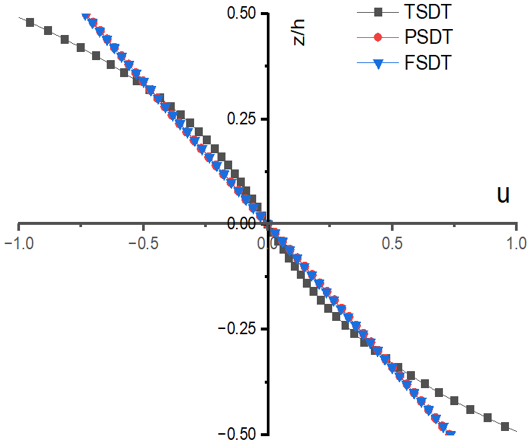
Axial displacement $(\bar{u})$: The axial displacement obtained by TSDT at low aspect ratio (S = 4) is slightly higher than PSDT and FSDT. As the aspect ratio increases to 10 and 100, the values obtained from all three theories converge, indicating that axial displacement becomes less sensitive to the choice of theory for thin beams.
Transverse displacement $(\bar{w})$: For thick beam (S = 4), TSDT yields the largest transverse displacement, while PSDT predicts the smallest. The transverse displacement obtained from FSDT lies close to PSDT. With increasing aspect ratio, the differences diminish and at S = 100, all three theories provide nearly identical results. This suggests that higher-order theories are more significant for thick beams, whereas for thin beams, simpler models are sufficient.
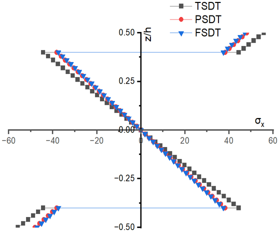
Normal stress $\left(\bar{\sigma}_x\right)$: At low aspect ratio (S = 4), TSDT predicts the most negative stress value, showing a stronger stress response compared to PSDT and FSDT. As the aspect ratio increases, the stress values from all theories converge around −47, demonstrating consistency across models for thin sandwich beam structures.
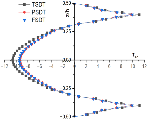
Transverse shear stress $\left(\bar{\tau}_{x z}^{E E}\right)$: It shows the most pronounced variation at low aspect ratio. TSDT predicts higher shear stresses than PSDT and FSDT at S = 4. However, as the aspect ratio (S) increases to 10 and 100, the values from all three theories become nearly identical with shear stress reducing significantly. This indicates that shear effects dominate in thick beams but diminish in thin beams. Transverse shear stress is computed using equation of equilibrium. The transverse shear stress obtained through the equilibrium equation reflects the true physical response of sandwich beam under thermal point load, capturing the interaction between axial stress, bending effects and shear transfer in the core material.
Figure 2. Variation of dimensionless axial deformation $(\bar{u})$ under thermal point load for aspect ratio 4
Figure 3. Variation of dimensionless axial stress $\left(\bar{\sigma}_x\right)$ under thermal point load for aspect ratio 4
Figure 4. Variation of dimensionless transverse shear stress $\left(\bar{\tau}_{z x}^{E E}\right)$ under thermal point load for aspect ratio 4
The through-thickness variations of axial displacement, normal stress and transverse shear stress are shown in Figures 2-4.
3.1.2 Discussion on thermal response characteristic under central thermal line loading (Table 5)
The results in Table 5 present the dimensionless thermal deformations and stresses of a three-layer sandwich beam subjected to thermal line load using TSDT, PSDT and FSDT.
Table 5. Dimensionless deformations and stresses under thermal line load
|
Model |
S |
$\bar{u}$ |
$\overline{{w}}$ |
$\overline{{\sigma}}_x$ |
$\bar{\tau}_{x z}^{E E}$ |
|
TSDT |
4 |
3.2363 |
3.8478 |
-379.5127 |
46.7401 |
|
PSDT |
4 |
2.8684 |
1.7629 |
-204.7197 |
43.6353 |
|
FSDT |
4 |
2.8854 |
1.8369 |
-201.6220 |
44.0223 |
|
TSDT |
10 |
2.9420 |
2.1611 |
-230.3078 |
17.7842 |
|
PSDT |
10 |
2.8827 |
1.8254 |
-202.1054 |
17.5812 |
|
FSDT |
10 |
2.8854 |
1.8369 |
-201.6220 |
17.6089 |
|
TSDT |
100 |
2.8860 |
1.8401 |
-201.9092 |
1.7611 |
|
PSDT |
100 |
2.8854 |
1.8368 |
-201.6268 |
1.7615 |
|
FSDT |
100 |
2.8854 |
1.8369 |
-201.6220 |
1.7609 |
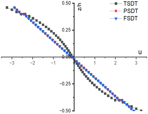
Axial displacement $(\bar{u})$: At S = 4, TSDT predicts the highest axial displacement, whereas PSDT and FSDT give lower but comparable values. As the aspect ratio increases to 10 and 100, the differences between the three theories diminish and results converge around 2.88. This indicates that axial displacement is more sensitive to higher-order theories in thick beams but becomes independent of theory for thin sandwich beams.
Transverse displacement $(\bar{w})$: For S = 4, TSDT shows a significantly larger transverse displacement compared to PSDT and FSDT, highlighting the importance of higher-order terms in capturing thermal deformations under thermal line loading. As the aspect ratio changes to 10, the gap reduces and at S = 100, all theories converge to nearly identical values (approximately 1.84).
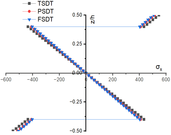
Normal stress $\left(\bar{\sigma}_x\right)$: The normal stress response is strongest at low aspect ratio (S = 4). At S = 4, TSDT predicts a much higher compressive stress compared to PSDT and FSDT. As aspect ratio (S) increases, the stress values obtained from all theories converge around 201. This indicates that the choice of theory has little impact on stress prediction for thin sandwich beams.
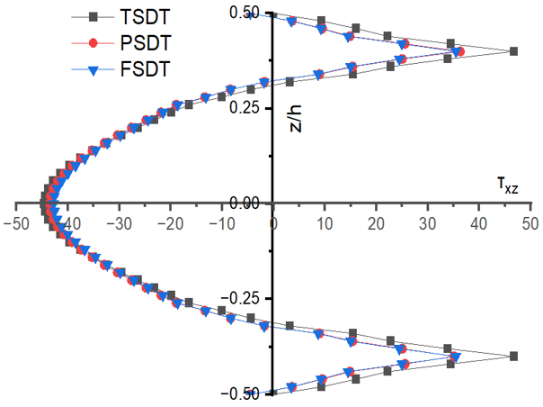
Transverse shear stress $\left(\bar{\tau}_{x z}^{E E}\right)$: The transverse shear stress is highest at low aspect ratio (S = 4), with TSDT predicting slightly larger values than PSDT and FSDT. As the aspect ratio increases, shear stress decreases sharply, reaching values around 1.76 at S = 100. This trend confirms that shear effects dominate in thick beams but diminish as sandwich becomes thin.
Figure 5. Variation of dimensionless axial deformation $(\bar{u})$ under thermal line load for aspect ratio 4
Figure 6. Variation of dimensionless axial stress $\left(\bar{\sigma}_x\right)$ under thermal line load for aspect ratio 4
Figure 7. Variation of dimensionless transverse shear stress $\left(\bar{\tau}_{z x}^{E E}\right)$ under thermal line load for aspect ratio 4
The through-thickness variation of axial displacement, normal stress and transverse shear stress for an aspect ratio of 4 is graphically represented in Figures 5-7. TSDT shows the realistic curve across the thickness in Figures 5 and 7 for axial displacement and transverse shear stress.
3.1.3 Discussion on thermal response characteristic under central thermal patch loading
The stresses and displacements obtained from the analysis of a three-layer sandwich beam (0°/core/0°) subjected to thermal patch load are presented in Table 6.
Table 6. Dimensionless deformations and stresses under thermal patch load
|
Model |
S |
$\bar{u}$ |
$\bar{w}$ |
$\overline{{\sigma}}_x$ |
$\bar{\tau}_{x z}^{E E}$ |
|
TSDT |
4 |
4.5768 |
5.4416 |
-547.0674 |
68.3615 |
|
PSDT |
4 |
4.0565 |
2.4931 |
-299.8727 |
63.9714 |
|
FSDT |
4 |
4.0806 |
2.5978 |
-295.4919 |
64.5179 |
|
TSDT |
10 |
4.1606 |
3.0563 |
-336.0598 |
26.0551 |
|
PSDT |
10 |
4.0768 |
2.5815 |
-296.1756 |
25.7683 |
|
FSDT |
10 |
4.0806 |
2.5978 |
-295.4919 |
25.8072 |
|
TSDT |
100 |
4.0814 |
2.6024 |
-295.8981 |
2.5810 |
|
PSDT |
100 |
4.0806 |
2.5976 |
-295.4987 |
2.5816 |
|
FSDT |
100 |
4.0806 |
2.5978 |
-295.4919 |
2.5807 |
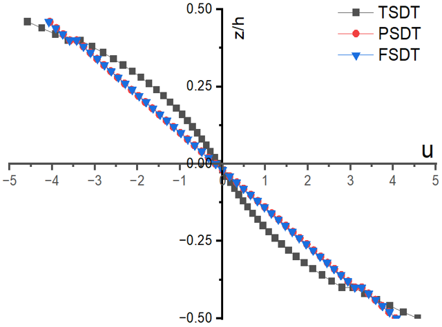
Axial displacement $(\bar{u})$: The values of axial displacements are relatively stable across theories and aspect ratios (S), ranging between 4.04 and 4.57. TSDT predicts slightly higher values at small aspect ratio, but convergence occurs as the aspect ratio grows.
Transverse displacement $(\bar{w})$: TSDT consistently predicts higher transverse displacements, especially at lower values of aspect ratio (S). For example, 5.44 at S = 4. The PSDT and FSDT give much lower values (around 2.5 to 2.6), showing closer agreement with each other. As the aspect ratio (S) increases towards 100, all three theories converge to nearly identical values (around 2.6), indicating diminishing influence of higher-order shear effects.
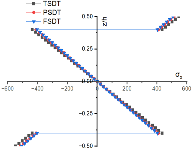
Normal stress $\left(\bar{\sigma}_x\right)$: At a small aspect ratio (S), TSDT predicts significantly higher compressive stresses (−547 at S = 4) compared to PSDT and FSDT (around −300). As the aspect ratio (S) increases, the stress values predicted by all theories converge to about −296, showing that the effect of higher-order terms diminishes with larger aspect ratio.
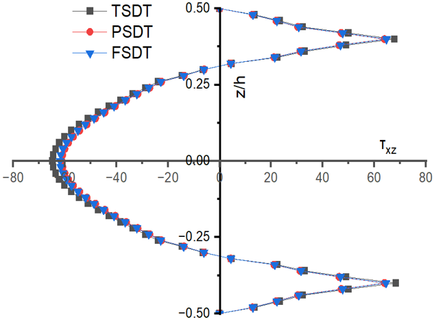
Transverse shear stress $\left(\bar{\tau}_{x z}^{E E}\right)$: At a small aspect ratio (S = 4), TSDT predicts slightly higher shear stress (68.36) compared to PSDT and FSDT (64). With increasing S, the shear stress values decrease sharply, converging to 2.58 at S = 100 across all theories. This indicates that shear effects are more pronounced at lower aspect ratios (i.e., thick beam (S = 4)), but negligible at higher aspect ratios (S).
Figure 8. Variation of dimensionless axial deformation $(\bar{u})$ under thermal patch load for aspect ratio 4
Figure 9. Variation of dimensionless axial stress $\left(\bar{\sigma}_x\right)$ under thermal patch load for aspect ratio 4
Figure 10. Variation of dimensionless transverse shear stress $\left(\bar{\tau}_{z x}^{E E}\right)$ under thermal patch load for aspect ratio 4
The variation of these stresses and axial displacement across the thickness of sandwich beam is shown in Figures 8-10. Figure 8 shows the through-thickness variation of axial displacement, whereas Figures 9 and 10 show through-thickness variation of normal stress and transverse shear stress, respectively.
3.2 Validation of the present formulation
To establish the accuracy of the present theories, results under sinusoidal thermal loading are compared with the closed-form thermoelastic solution reported by Kulkarni and Ghugal [26]. Table 7 presents the comparison for displacement and stress parameters at different aspect ratios (S = 4, 10, 100). The close agreement with the published benchmarks confirms the validity of the present theories, while the slight deviations observed for TSDT highlight the influence of considering $\varepsilon_z \neq 0$.
Table 7. Validation of present theory results against published analytical solutions
|
Theory |
S |
$\bar{u}$ |
$\overline{{w}}$ |
$\overline{{\sigma}}_x$ |
$\bar{\tau}_{z x}^{E E}$ |
|
|
|
z = −0.5 h |
z = 0 |
z = −0.5 h |
z = −0.4 h |
|
TSDT (Present) $\varepsilon_z \neq 0$ |
4 |
0.5151 |
0.6124 |
−15.8549 |
0.8505 |
|
PSDT (Present) $\varepsilon_z \neq 0$ |
4 |
0.4565 |
0.2806 |
−11.5610 |
0.7616 |
|
FSDT (Present) |
4 |
0.4592 |
0.2924 |
−11.0680 |
0.7854 |
|
Kulkarni and Ghugal [26] $\varepsilon_z=0$ |
4 |
0.4330 |
0.2917 |
−11.0686 |
0.7485 |
|
TSDT (Present) $\varepsilon_z \neq 0$ |
10 |
0.4682 |
0.3440 |
−11.0751 |
0.3198 |
|
PSDT (Present) $\varepsilon_z \neq 0$ |
10 |
0.4588 |
0.2905 |
−11.1450 |
0.3112 |
|
FSDT (Present) |
10 |
0.4592 |
0.2924 |
−11.0680 |
0.3142 |
|
Kulkarni and Ghugal [26] $\varepsilon_z=0$ |
10 |
0.4548 |
0.2653 |
−11.0687 |
0.3107 |
|
TSDT (Present) $\varepsilon_z \neq 0$ |
100 |
0.4593 |
0.2929 |
−11.7753 |
0.0311 |
|
PSDT (Present) $\varepsilon_z \neq 0$ |
100 |
0.4592 |
0.2806 |
−11.0688 |
0.0313 |
|
FSDT (Present) |
100 |
0.4592 |
0.2924 |
−11.0680 |
0.0314 |
|
Kulkarni and Ghugal [26] $\varepsilon_z=0$ |
100 |
0.4592 |
0.2921 |
−11.0651 |
0.0313 |
For S = 10 and S = 100, the present PSDT and FSDT results are in excellent agreement with Kulkarni and Ghugal [26], with differences less than 1 to 2%. For S = 4, the present TSDT predicts slightly higher transverse displacement and axial stress, reflecting the inclusion of $\varepsilon_z \neq 0$. This demonstrates the improved realism of TSDT in capturing through-thickness strain effects. As the aspect ratio increases, all theories converge to the benchmark results, confirming the consistency and stability of the formulations.
Thus, the present theory results are validated against published analytical benchmarks, supporting the conclusion that PSDT and FSDT are acceptable approximations, while TSDT provides a more conservative representation of thermoelastic behaviour in sandwich beams.
The validation study against published analytical thermoelastic solutions demonstrates good agreement of the present formulations, particularly for moderate and high aspect ratios. TSDT predicts comparatively higher displacement and stress values for thick sandwich beams (S = 4), indicating a more conservative estimation due to the inclusion of transverse normal strain effects. However, as the aspect ratio increases, the differences among TSDT, PSDT and FSDT reduce significantly. For higher aspect ratios (S > 50), the deviation among the theories becomes marginal, suggesting that simplified beam theories such as PSDT and FSDT provide acceptable approximations for thin sandwich beams under localized thermal loading.
The limitation of the present study is that it is restricted to three-layer symmetric sandwich beams and specific thermal loading conditions, such as thermal point, line and patch loads. Material nonlinearity, temperature-dependent properties and dynamic effects are not considered in the present study.
The future work of this study is to extend this work to analyze asymmetric and multilayered sandwich beams subjected to nonlinear thermal loadings.
The authors sincerely acknowledge the support and facilities provided by Symbiosis Institute of Technology, Pune, during the completion of this work.
|
$ \varepsilon_x$ |
Normal strain |
|
$ \gamma_{z x}$ |
Shear strain |
|
E |
Modulus of Elasticity |
|
G |
Shear modulus |
|
$ \bar{u}$ |
Normalized axial displacement |
|
$ \bar{w}$ |
Normalized transverse displacement |
|
$ \partial_x$ |
$ \frac{\partial}{\partial x}$ |
|
$ \bar{\sigma}_x$ |
Normalized Normal Stress |
|
$ \bar{\tau}_{z x}^{E E}$ |
Normalized Transverse Shear Stress obtained by using equilibrium equation. |
|
$ \left(\bar{Q}_{i j}\right)$ |
Reduced stiffness coefficient |
|
S |
Aspect Ratio $ \left(S=\frac{a}{h}\right)$ |
|
Greek symbols |
|
|
$ \alpha_x$ |
Coefficient of thermal expansion in x direction |
|
$ \alpha_z$ |
Coefficient of thermal expansion in z direction |
|
$ \delta$ |
Variational operator |
|
$ \mu_{i j}$ |
Poisson’s ratio |
|
$ \alpha_0$ |
Normalization factor for thermal coefficient |
[1] Carrera, E., Brischetto, S. (2009). A survey with numerical assessment of classical and refined theories for the analysis of sandwich plates. Applied Mechanics Reviews, 62(1): 010803. https://doi.org/10.1115/1.3013824
[2] Phan, C.N., Frostig, Y., Kardomateas, G.A. (2012). Analysis of sandwich beams with a compliant core and with in-plane rigidity-extended high-order sandwich panel theory versus elasticity. Journal of Applied Mechanics, 79(4): 041001. https://doi.org/10.1115/1.4005550
[3] Nguyen, T.K., Thuc P. Vo, Nguyen, B.D., Lee, J. (2016). An analytical solution for buckling and vibration analysis of functionally graded sandwich beams using a quasi-3D shear deformation theory. Composite Structures, 156: 238-252. https://doi.org/10.1016/j.compstruct.2015.11.074
[4] Sayyad, A.S., Naik, N.S. (2019). New displacement model for accurate prediction of transverse shear stresses in laminated and sandwich rectangular plates. Journal of Aerospace Engineering, 32: 1-12. https://doi.org/10.1061/(ASCE)AS.1943-5525.0001074
[5] Belarbi, M.O., Garg, A., Houari, M.S.A., Hirane, H., Tounsi, A., Chalak, H.D. (2022). A three-unknown refined shear beam element model for buckling analysis of functionally graded curved sandwich beams. Engineering with Computers, 38(5): 4273-4300. https://doi.org/10.1007/s00366-021-01452-1
[6] Carrera, E. (2005). Transverse normal strain effects on thermal stress analysis of homogeneous and layered plates. AIAA Journal, 43(10): 2232-2242. https://doi.org/10.2514/1.11230
[7] Sayyad, A.S., Ghugal, Y.M., Naik, N.S. (2015). Bending analysis of laminated composite and sandwich beams according to refined trigonometric beam theory. Curved and Layered Structures, 2(1): 279-289. https://doi.org/10.1515/cls-2015-0015
[8] Zenkour, A.M., Alghamdi, N.A. (2010). Bending analysis of functionally graded sandwich plates under the effect of mechanical and thermal loads. Mechanics of Advanced Materials and Structures, 17(6): 419-432. https://doi.org/10.1080/15376494.2010.483323
[9] Ebrahimi, F., Farazmandnia, N. (2016). Thermo-mechanical vibration analysis of sandwich beams with functionally graded carbon nanotube-reinforced composite face sheets based on a higher-order shear deformation beam theory. Mechanics of Advanced Materials and Structures, 24(10): 820-829. https://doi.org/10.1080/15376494.2016.1196786
[10] Daikh, A.A., Megueni, A. (2017). Thermal buckling analysis of functionally graded sandwich plates. Journal of Thermal Stresses, 41(2): 139-159. https://doi.org/10.1080/01495739.2017.1393644
[11] Swaminathan, K., Sangeetha, D.M. (2017). Thermal analysis of FGM plates-A critical review of various modeling techniques and solution methods. Composite Structures, 160: 43-60. https://doi.org/10.1016/j.compstruct.2016.10.047
[12] Naik, N.S., Sayyad, A.S. (2019). An accurate computational model for thermal analysis of laminated composite and sandwich plates. Journal of Thermal Stresses, 42(5): 559-579. https://doi.org/10.1080/01495739.2018.1522986
[13] Singh, S.J., Harsha, S.P. (2020). Thermo-mechanical analysis of porous sandwich S-FGM plate for different boundary conditions using Galerkin Vlasov's method: A semi-analytical approach. Thin-Walled Structures, 150: 106668. https://doi.org/10.1016/j.tws.2020.106668
[14] Cho, J.R. (2022). Thermoelastic analysis of functionally graded sandwich plates with a homogeneous core. Journal of Mechanical Science and Technology, 36: 4583-4592. https://doi.org/10.1007/s12206-022-0821-3
[15] Houari, M.S.A., Bessaim, A., Bezzina, S., Tounsi, A. (2023). Thermal bending analysis of functionally graded thick sandwich plates including stretching effect. Structural Engineering and Mechanics, 86(3): 373-384. https://doi.org/10.12989/sem.2023.86.3.373
[16] Kulkarni, S.K. (2025). A computational model for transverse thermal displacements in symmetric sandwich beam by using higher order shear deformation theory. Mathematical Modelling of Engineering Problems, 12(3): 917-924. https://doi.org/10.18280/mmep.120318
[17] Arikoglu, A., Ozkol, I. (2010). Vibration analysis of composite sandwich beams with viscoelastic core by using differential transform method. Composite Structures, 92(12): 3031-3039. https://doi.org/10.1016/j.compstruct.2010.05.022
[18] Arvin, H., Sadighi, M., Ohadi, A.R. (2010). A numerical study of free and forced vibration of composite sandwich beam with viscoelastic core. Composite Structures, 92(4): 996-1008. https://doi.org/10.1016/j.compstruct.2009.09.047
[19] Lou, J., Ma, L., Wu, L.Z. (2012). Free vibration analysis of simply supported sandwich beams with lattice truss core. Materials Science and Engineering: B, 177(19): 1712-1716. https://doi.org/10.1016/j.mseb.2012.02.003
[20] Bui, T.Q., Khosravifard, A., Zhang, C., Hematiyan, M.R., Golub, M.V. (2013). Dynamic analysis of sandwich beams with functionally graded core using a truly meshfree radial point interpolation method. Engineering Structures, 47: 90-104. https://doi.org/10.1016/j.engstruct.2012.03.041
[21] Wu, H.L., Kitipornchai, S., Yang, J. (2015). Free vibration and buckling analysis of sandwich beams with functionally graded carbon nanotube-reinforced composite face sheets. International Journal of Structural Stability and Dynamics, 15(7): 1540011. https://doi.org/10.1142/S0219455415400118
[22] Yan, J.B., Liew, J.Y.R., Zhang, M.H., Sohel, K.M.A. (2015). Experimental and analytical study on ultimate strength behavior of steel-concrete-steel sandwich composite beam structures. Materials and Structures, 48: 1523-1544. https://doi.org/10.1617/s11527-014-0252-4
[23] Sayyad, A.S., Ghugal, Y.M. (2017). Bending, buckling and free vibration of laminated composite and sandwich beams: A critical review of literature. Composite Structures, 171: 486-504. https://doi.org/10.1016/j.compstruct.2017.03.053
[24] Sayyad, A.S., Ghugal, Y.M. (2018). Modeling and analysis of functionally graded sandwich beams: A review. Mechanics of Advanced Materials and Structures, 26(21): 1776-1795. https://doi.org/10.1080/15376494.2018.1447178
[25] Lin, J., Su, X.Y., Chen, D., Yang, F., Zhao, L.M. (2019). Experimental and numerical study of sandwich beams with layered-gradient foam cores under low-velocity impact. Thin-Walled Structures, 135: 227-244. https://doi.org/10.1016/j.tws.2018.11.011
[26] Kulkarni, S., Ghugal, Y.M. (2020). Closed-form solutions for laminated composite and sandwich beams loaded by temperature field. Composites: Mechanics, Computations, Applications: An International Journal, 11(3): 239-265. https://doi.org/10.1615/CompMechComputApplIntJ.2020032576
[27] Onyibo, E.C., Safaei, B. (2022). Application of finite element analysis to honeycomb sandwich structures: A review. Reports in Mechanical Engineering, 3(1): 283-300. https://doi.org/10.31181/rme20023032022o
[28] Lu, Q.F., Wang, P., Liu, C.C. (2022). An analytical and experimental study on adaptive active vibration control of sandwich beam. International Journal of Mechanical Sciences, 232: 107634. https://doi.org/10.1016/j.ijmecsci.2022.107634