Ngoc Thoai Nguyen![]() | Tuan Dat Vu*
| Tuan Dat Vu*![]() | Van Nhu Tran
| Van Nhu Tran![]() | Xuan Ngoc Nguyen
| Xuan Ngoc Nguyen![]() | Thanh Tam Tran
| Thanh Tam Tran![]()
© 2025 The authors. This article is published by IIETA and is licensed under the CC BY 4.0 license (http://creativecommons.org/licenses/by/4.0/).
OPEN ACCESS
The diaphragm spring of the dry friction clutch is the main load-bearing part and has a large deformation when the clutch is operating. With a thin disc structure, the thickness of the diaphragm spring has a significant influence on its structural strength. In this study, a finite element model with basic structural parameters of diaphragm springs used on light-duty vehicles is established to analyze the stress, deformation and safety factor of the part under static load. In this model, the thickness of the diaphragm spring is parameterized based on the relationship with other dimensional parameters. From the calculation results, the thickness of the diaphragm spring of 2.0 mm is a reasonable choice, not only ensuring the structural strength but also reducing the production cost. These outcomes of this research offer valuable information regarding the design and durability assessment of clutch assembly parts.
diaphragm spring, finite element, hydraulic clutch, safety factor, Ansys
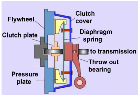
On a manual transmission vehicle, when you want to change gears, you have to depress the clutch. When you press the clutch pedal, the pressure created from the master cylinder is transmitted to the clutch release cylinder. At this time, a force will be applied to the throw out bearing and the bearing will squeeze the diaphragm spring. The diaphragm spring will pull the pressure plate away from the clutch plate based on the lever rule, then shift gears [1]. The system operation is shown in Figure 1. This shows that the clutch operates continuously, so it is easy to cause damage.
Figure 1. Friction clutch structure on vehicle
Currently, the issue of research on clutch durability is still of interest to scientists in order to prolong its life and efficiency. Changes in manufacturing materials are also considered to optimize the car's clutch. Specifically in the study [2], the authors changed the material to optimize the friction layer of the clutch disc, the 3D model of the friction disc was built from SolidWorks and the performance was considered using Ansys to come up with the most suitable material. Some authors selected three types of materials for finite element analysis (FEA) including cast carbon steel, Monel(R) 400, composites with aluminum and ceramic particles [3]. Here, the study created a clutch model and performed thermal and motion analysis. The first two materials are commonly used in the manufacture of clutches. The third material scores better in motion simulation, which means better mechanical properties. Its thermal properties are not the best but are sufficient to provide end product reliability under normal thermal conditions for upper clutches. Or in other research, the authors proposed five types of materials for making automobile clutch friction discs to consider the temperature factor during the friction process [4]. Using Ansys to analyze the results, it was shown that Kevlar material increased temperature less than other materials, so its durability was higher than other materials. Research on materials, the authors designed a clutch friction disc model using Catia, then applied Ansys to analyze the deformation and stress of the disc corresponding to each different material, then compared the results to select the appropriate material for the disc friction layer [5]. With the design of clutch friction disc on SolidWorks software with different materials, then the analysis is performed in a static state to determine the stress and strain by Ansys, the result was that cast iron is most suitable for fabricating the friction disc [6] and likewise the authors in the study [7] designed and modeled the clutch. single disc using Catia V5, simulation shows that the metal matrix composite material is better than the remaining materials. Furthermore, Danev et al. [8] also successfully improved the performance of the clutch friction disc of vehicle when using basalt fiber material as the friction lining.
In addition, the optimization of automobile clutches by providing operating methods or design structural parameter ratios through simulation. As in the case study of Yan and Li, the authors use the stress-strength integration model for automobile clutches to determine operational reliability [9]. The article also combines analysis methods such as fault tree (FTA), failure modes and effects (FMEA) to count the number of failures of vehicles using clutches regularly to provide technical guidance or improve the stress and contact area of the clutch. The method of using reference values for comparison is mentioned in the study [10] on the slippage and torque when the clutch is in the connected state, the paper uses AMESIM and MATLAB Simulink to simulate the energy loss and discomfort during the clutch engagement process, thereby increasing the service life and smoothness when shifting gears. The optimization of the design of the diaphragm spring of the automobile clutch can be calculated by Matlab according to the size ratios within the allowable range, then FEA for the 3D model by Ansys to optimize the load capacity and reduce vibration of the clutch [11]. Similarly, the authors also simulated the load and deformation characteristics of the clutch using Matlab to determine the optimal structural parameter ratios after being calculated and designed using genetic algorithms [12]. The authors in research [13] designed a conical Belleville spring using the Explicit Dynamics Theory method on a finite element model according to DIN 2093. They also combined numerical analysis to calculate key spring parameters, including thickness and diameter. The results of the study show that Belleville springs have good performance and durability in different conditions. Besides, the study of Zheng et al. [14] used SolidWorks and finite analysis combined with nonlinear methods to calculate and improve the parameters of the cone clutch spring including load, ductility, stiffness and deformability. Analysis of the Belleville spring's nonlinear characteristics shows that the stiffness of the spring decreases with increasing strain and this value tends to stabilize when the spring is forced under load. When the ratio between the height and thickness of the spring increases to the root of 2π, a negative stiffness area will appear and affect the spring's operation, causing instability. However, the stiffness characteristic of the Belleville spring with the support surface can be improved, and as the width of the support surface increases, the stiffness of the Belleville spring will increase.
From the above-mentioned studies in the world, clutches in general or diaphragm springs in particular are currently receiving much attention due to the need to improve the quality of automobile products. However, the design and calculation of diaphragm springs of clutches have not received much attention. Most studies on optimizing automobile clutches only focus on changing materials or structural parameter ratios, without specifically determining the parameters of the part that needs to be changed. Therefore, in this study, the article proposes to change the thickness of the clutch diaphragm spring through a 3D model built from SolidWorks, FEA using Ansys to simulate the deformation characteristics of the part to improve the quality and life of the clutch diaphragm spring on the vehicle.
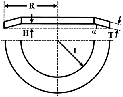
The clutch proposed in this study is used in passenger cars. This part is located between the engine and the mechanical transmission. It consists of a friction disc, a pressure disc, a spring and a clutch housing. Its function is to connect and disconnect the transmission of torque from the engine to the gearbox. Therefore, the spring details work continuously, so they require durability and long life. Optimizing the size parameter of the diaphragm spring is necessary. Based on the initial structural parameters of the diaphragm spring mentioned in the study [11, 15] to use SolidWorks to simulate its 2D dimensions as shown in Figure 2 below:
Figure 2. The diaphragm spring parameters
The cone angle in the free state must satisfy the condition between 90 and 150 [12] and is determined by Eq. (1).
$\alpha=arctan \left(\frac{H}{R-L}\right)$ (1)
When under pressure acting on the diaphragm spring, its radius now depends on the conditions of radius of diaphragm spring in free state and distance from the center to the beginning of the diaphragm spring presented by Eq. (2) as follows:
$\frac{2 * R+2 * L}{4}<2 * R_L<\frac{2 * R}{2}$ (2)
The values of the symbols in Figure 2 and the equations are shown in Table 1 [12] as follows:
Table 1. Specifications of diaphragm spring
|
Symbols |
Value |
Symbols |
Value |
|
R |
80.01 |
T |
2 |
|
H |
3.5 |
L |
62.12 |
Substituting the values of Table 1 into Eqs. (1) and (2), the study calculated the values of the cone angle of inclination and radius of diaphragm spring in loaded state as 11.070 and 76.41 mm respectively. The material used for diaphragm spring is steel [11, 16] with properties of Modulus of elasticity, Yield strength, Poison’s ratio corresponding to values of 2.0 × 10⁵ MPa, 379 MPa, 0.3.
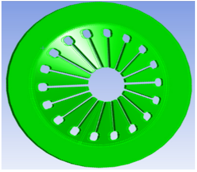
Based on the structure and basic dimensions of the diaphragm spring, SolidWorks is used to build its 3D model as Figure 3.
Figure 3. The diaphragm spring model of the vehicle clutch
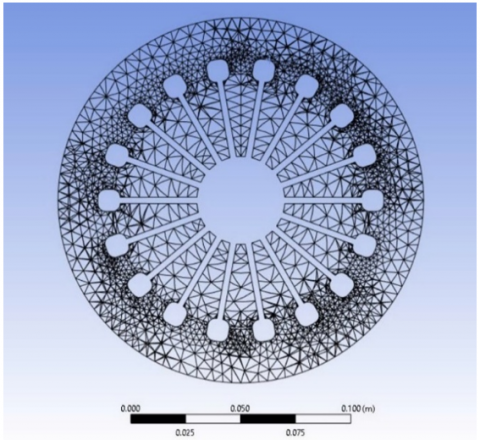
Diaphragm springs have quite a shape so before performing FEA, the 3D model of the diaphragm spring needs to be divided into small points called model meshing [17, 18]. The resulting mesh is a tetrahedral mesh, solid elements type with 27529 nodes and 12700 elements shown in Figure 4.
Figure 4. Meshing model of diaphragm spring
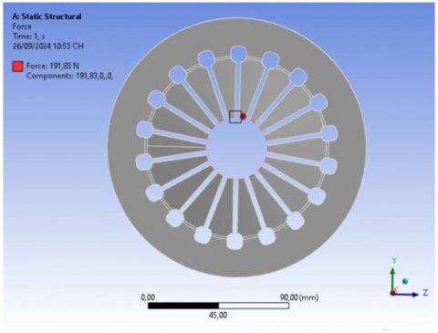
Figure 5. Model of force applied on diaphragm spring
After the model is meshed, based on the operating principle of the clutch, the force applied at the tip of each finger of the diaphragm spring is 191.83 N [19] where it contacts the throw out bearing as indicated in Figure 5.
The study needs to determine the required thickness of the diaphragm spring, the thickness T and the inner truncated cone thickness H need to be suitable for the conditions [12]:
$1.5 \leq \frac{H}{T} \leq 2.2$ (3)
Therefore, the thickness T will be changed in the dimensional cases as shown in Table 2.
Table 2. Diaphragm spring thickness dimensions
|
H (mm) |
3.5 |
||||
|
T (mm) |
1.7 |
1.8 |
1.9 |
2.0 |
2.1 |
After improving and designing the spring thickness T using Solidworks software, applying the finite element method to analyze the deformation and stress of the diaphragm spring model, this implementation method is similar to that in the study [20]. Ansys application to simulate the displacement and stress results of diaphragm spring is described from Figures 6 to 10 for each size as follows:
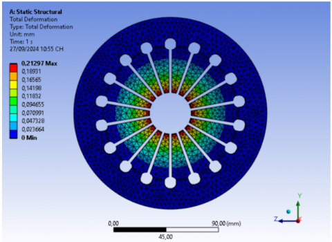
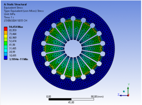
For diaphragm spring thickness 1.7 mm:
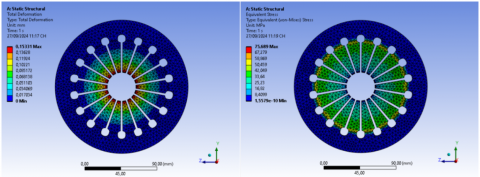
Figure 6. Deformation and stress in the case of spring thickness 1.7 mm
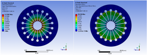
For diaphragm spring thickness 1.8 mm:
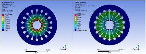
Figure 7. Deformation and stress in case of spring thickness 1.8 mm
For diaphragm spring thickness 1.9 mm:
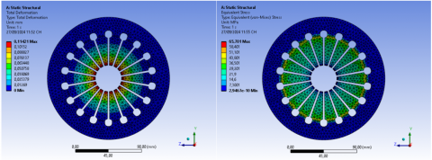
Figure 8. Deformation and stress in case of spring thickness 1.9 mm
For diaphragm spring thickness 2.0 mm:
Figure 9. Deformation and stress in case of spring thickness 2.0 mm
For diaphragm spring thickness 2.1 mm:
Figure 10. Deformation and stress in case of spring thickness 2.1 mm
Simulation results about the deformation (above figure) and stress (below figure) of the automobile clutch diaphragm spring from Figures 6 to 10 show that the largest deformation is concentrated in the center of the diaphragm spring, the deformation decreases as it moves further away from the center of the spring or closer to the outer radius of the spring. The maximum stress is concentrated right at the foot of the diaphragm spring (the outer radius of the diaphragm spring), the further towards the center, the lower the maximum stress. In the case of a diaphragm spring with a thickness of 1.7 mm, the largest deformation is 0.21297 mm and the largest stress is 94.454 MPa. On the contrary, in the case of a thickness of 2.1 mm, the smallest deformation is 0.11421 mm and the smallest stress is 65.701 MPa.
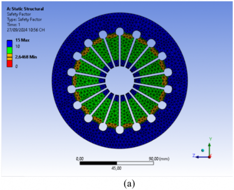
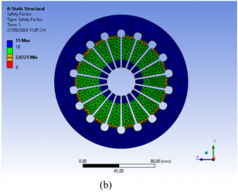
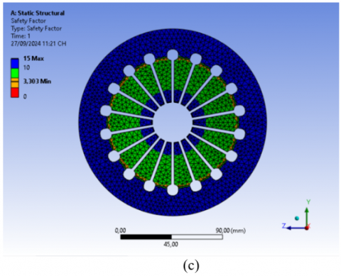
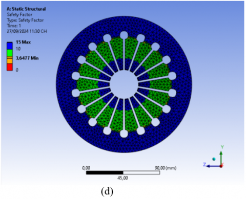
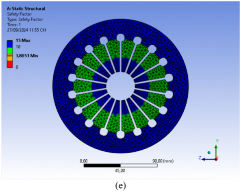
In addition, the study needs to consider the safety factor of the material used to manufacture the diaphragm spring corresponding to each different size. The safety factor is determined based on simulation results from material data sources corresponding to each size of the diaphragm spring. This factor must be greater than 1.2 as in the study [21, 22], it is shown in Figure 11 as follows:
Figure 11. Safety factor in case of diaphragm spring thickness is 1.7 (a), 1.8 (b), 1.9 (c), 2.0 (d), 2.1 mm (e)
The values obtained from the simulation results are summarized in Table 3.
Table 3. Deformation, stress and safety factor values corresponding to diaphragm spring thicknesses
|
T (mm) |
Stress (MPa) |
Deformance (mm) |
Safety Factor |
|
1.7 |
94.454 |
0.21297 |
2.6468 |
|
1.8 |
84.106 |
0.17987 |
2.9725 |
|
1.9 |
75.689 |
0.15331 |
3.303 |
|
2.0 |
68.536 |
0.13173 |
3.6477 |
|
2.1 |
65.701 |
0.11421 |
3.8051 |
Table 3 lists the deformation, stress and safety factor values corresponding to each case of different thickness dimensions of the diaphragm spring, it can be seen that the safety factor tends to increase corresponding to the thickness of the diaphragm spring and it is inversely proportional to the deformation and stress. The highest safety factor is at the size of 2.1 mm and the lowest is at 1.7 mm. As the thickness increases, the deformation and stress decrease, and the safety factor increases.
For hydraulic clutch diaphragm springs, the choice of its structural parameters will depend on the deformation and safety factor, and the stress is considered last. Based on the operating principle of the clutch, the diaphragm spring needs to be closed/opened decisively, the deformation is small because if it is too large, the clutch disengagement process will not occur, which will cause the manual transmission to not be able to shift gears. If the safety factor is too high, it will increase the manufacturing cost. Therefore, the study recommends the thickness of the diaphragm spring to be 2.0 mm because compared with the upper and lower values for the remaining sizes, its deformation and safety factor are not much different, and the stress is higher than the size of 2.1 mm, this proposal is similar to the research results [23, 24].
Proposing optimal design parameters for diaphragm springs of hydraulic clutches on automobiles is the main objective of this study. The paper has built a 3D model of diaphragm springs using SolidWorks from previous research results. Using the finite element method for spatial modeling to analyze deformation, stress and safety factor of diaphragm springs corresponding to thicknesses of 1.7, 1.8, 1.9, 2.0, 2.1 mm using Ansys. From the simulation results, it is suggested that the selected diaphragm spring thickness is 2.0 mm with a deformation of 0.13173 mm, a stress of 68.536 MPa and a safety factor of 3.6477, which is suitable for the clutch's performance and saves spring manufacturing costs. This research work is applied in factories manufacturing automobile clutch components or used as basic knowledge to further improve other components of the clutch diaphragm spring.
|
R |
Radius of diaphragm spring in free state (mm) |
|
H |
Inner truncated cone thickness (mm) |
|
T |
Diaphragm spring thickness (mm) |
|
L |
Distance from the center to the beginning of the diaphragm spring (mm) |
|
RL |
Radius of diaphragm spring in loaded state (mm) |
|
Greek symbols |
|
|
$\alpha$ |
The cone angle is in the free state (degree) |
[1] Syambabu Nutalapati, D.D.A., Naidu, D.G.S. (2017). Structural analysis of friction clutch plate by changing fillet radius. International Journal of Engineering Research-Online, 5(1): 79-86.
[2] Virmani, K., Madhogaria, T., Baskar, P. (2021). Design optimization of friction lining of a clutch plate. Materials Today: Proceedings, 46: 8009-8024. https://doi.org/10.1016/j.matpr.2021.02.775
[3] Glodova, I., Lipták, T., Bocko, J. (2014). Usage of finite element method for motion and thermal analysis of a specific object in SolidWorks environment. Procedia Engineering, 96: 131-135. https://doi.org/10.1016/j.proeng.2014.12.131
[4] Vo, L.K.T., Nguyen, X.N., Nguyen, B.L., Tran, T.T. (2023). Analysis of the effect of materials on the thermal change of the clutch friction disc. In the International Conference on Sustainable Energy Technologies, Ho Chi Minh City, Vietnam, pp. 495-503. https://doi.org/10.1007/978-981-97-1868-9_50
[5] Narayan, S., Grujic, I., Stojanovic, N., Usman, K.M., Shitu, A., Mahroogi, F.O. (2018). Design and analysis of an automotive single plate clutch. Mobility & Vehicle Mechanics, 44(1): 13-26. https://doi.org/10.24874/mvm.2018.44.01.02
[6] Deshbhratar, V.J., Kakde, N.U. (2013). Design and structural analysis of single plate friction clutch. International Journal of Engineering Research and Technology, 2(10): 3726-3732.
[7] Sahu, M., Jain, A.K. (2018). Finite element analysis of single plate clutch by using Ansys. International Journal for Research in Applied Science & Engineering Technology (IJRASET), 6(VI): 1337-1346. https://doi.org/10.22214/ijraset.2018.6195
[8] Danev, D., Simeonov, S., Jordanovska, V. (2016). Impact of basalt based thread linings on the tribological parameters of the clutch linings for motor vehicles. Tehnički vjesnik/Technical Gazette, Trg Ivane Brlić-Mažuranić 2, 35000 Slavonski Brod, 23(4): 1227-1232. https://doi.org/10.17559/TV-20150205075454
[9] Yan, Z.F., Li, G.H. (2014). Passenger vehicle clutch reliability optimization based on the stress-strength interference model. Applied Mechanics and Materials, 509: 86-91. https://doi.org/10.4028/www.scientific.net/AMM.509.86
[10] Park, J., Choi, S. (2021). Optimization method of reference slip speed in clutch slip engagement in vehicle powertrain. International Journal of Automotive Technology, 22(1): 55-67. https://doi.org/10.1007/s12239-021-0007-5
[11] Guo, C.X., Zhang, H.Z. (2014). Optimization design for the diaphragm spring of automobile clutch. Advanced Materials Research, 889: 268-271. https://doi.org/10.4028/www.scientific.net/AMR.889-890.268
[12] Chen, S., Zhang, L., Cheng, X. (2015). Genetic algorithm optimal design on diaphragm spring by Matlab. In 2015 2nd International Conference on Electrical, Computer Engineering and Electronics, pp. 186-190. https://doi.org/10.2991/icecee-15.2015.42
[13] Chidambarathanu, G.K., Nair, V., Stanis, S.M. (2020). Structural analysis of belleville spring used in automatic shift transmission multi-plate wet clutch for off-highway application (No. 2020-28-0491). SAE Technical Paper. https://doi.org/10.4271/2020-28-0491
[14] Zheng, E., Jia, F., Zhou, X. (2014). Energy-based method for nonlinear characteristics analysis of Belleville springs. Thin-Walled Structures, 79: 52-61. https://doi.org/10.1016/j.tws.2014.01.025
[15] Rupnar, A., Babar, A., Karale, A., Gundawar, S. (2016). Design and analysis of diaphragm spring of a single plate dry clutch. International Journal of Science Technology & Engineering, 2(12): 26-30.
[16] Abdulhameed, A.Z., Ahmed, M.A., Karim, A.A. (2023). The impact of bracing system distribution and location on seismic performance enhancement of multi-story steel buildings. Mathematical Modelling of Engineering Problems, 10(5): 1833-1841. https://doi.org/10.18280/mmep.100536
[17] Ouyoussef, N., Moustabchir, H. (2023). Predicting fracture placement and analyzing fatigue life in exhaust manifold systems using Finite Element Analysis. Journal Européen des Systèmes Automatisés, 56(3): 493-499. https://doi.org/10.18280/jesa.560317
[18] Nguyen, K.N., Vo, L.K.T., Nguyen, T.D. (2025). CFD analysis of the rear wing angle to aerodynamic characteristics on the Audi TT. Mathematical Modelling of Engineering Problems, 12(7): 2493-2501. https://doi.org/10.18280/mmep.120727
[19] Maw, T.T., Thar, I.I., Minn, P.P. (2019). Design of single plate clutch system. International Journal of Scientific Engineering and Technology Research, 8: 430-433. https://ijsetr.com/uploads/316425IJSETR17554-91.pdf.
[20] Chi, P.D., Huu, H.B., Quoc, V.D., Minh, D.B. (2025). Analytical and finite element methods for evaluative electromagnetic parameters of inset PMSM and SPMSM. Journal Européen des Systèmes Automatisés, 58(2): 337-343. https://doi.org/10.18280/jesa.580214
[21] Ramli, M.N., Sulaiman, S., Azizul, M.A. (2020). Implementation of weight reduction method for lower front control arm without reducing the safety factor. Journal of Design for Sustainable and Environment, 2(2).
[22] Yasin, S.B.M., Aziz, K.N.A., Bakar, I.A.A., Hayeemasae, N., Asiah, S.N. (2018). Durability of helmet material under longitudinal and lateral drop impact. AIP Conference Proceedings, 2031(1): 020035. https://doi.org/10.1063/1.5066991
[23] Nguyen, X.N., Dang, T.P., Vo, K.D., Tran, T.T. (2024). Influence of material properties on the durability of automotive hydraulic brake discs: A finite element analysis approach. Revue des Composites et des Matériaux Avancés-Journal of Composite and Advanced Materials, 34(6): 767-773. https://doi.org/10.18280/rcma.340611
[24] Nguyen, X.N., Tran, V.N., Mai, D.T., Tran, T.T. (2025). Influence of diagonal groove width on stress distribution and deformation behavior of automotive clutch friction discs. Revue des Composites et des Matériaux Avancés-Journal of Composite and Advanced Materials, 35(3): 451-457. https://doi.org/10.18280/rcma.350306