Hussain H. Al-Kayiem![]() | Ali M. Tukkee*
| Ali M. Tukkee*![]() | Azeem Uddin
| Azeem Uddin![]() | Haroun A.K. Shahad
| Haroun A.K. Shahad![]() | Hasanain A. Abdul Wahhab
| Hasanain A. Abdul Wahhab![]()
© 2025 The authors. This article is published by IIETA and is licensed under the CC BY 4.0 license (http://creativecommons.org/licenses/by/4.0/).
OPEN ACCESS
The solar chimney power plant is a growing power generation technology for sustainable, clean power generation. The setbacks of the technology are the remarkably small ratio of power produced to the plant size and the production interruption during the night. The objective of the current research is to investigate the recovery of waste thermal energy in the flue gases released from thermal power plants and charge it as an input to enable continuous operation of the hybrid power plant during the night. The proposed supply of the external flue gas thermal content is by inserting metal channels inside the collector of the solar chimney power plant, with a flue gas flow rate of 24.5 kg/s per channel at 370℃. A mathematical model was developed for the aerothermodynamics predictions of the hybrid solar plant and interconnected with ANSYS software to estimate the effects of the thermal recovery of the exhaust gas on the hybrid SCPP performance. The results show a significant increase in performance. At 1000 W/m2 solar irradiance, the power output using four channels of exhaust gases in the hybrid system was 67 kW compared to 49.04 kW in the conventional solar chimney power plant. The predicted mean daily collector efficiency under solar mode is 34.3%, which increased to around 78.5% under the hybrid mode, showing a mean daily efficiency enhancement of 56%. The updraft velocity at the chimney base has increased to 17.76 m/s, whereas it is 16.05 m/s under solar mode. The important performance parameter in the solar updraft systems is the air temperature rise across the collector. Results show that the air temperature increased to 24.5 K in the hybrid power plant system compared to 20.06 K in the traditional solar chimney power plant. The proposed hybrid system highly increased the system's performance and resolved the issue of night interruption.
energy recovery, energy sustainability, flue gas, hybrid solar chimney, integrated energy system, integrated solar collector, waste heat
A solar chimney power plant (SCPP) is a renewable energy technology powered by the sun. The idea of the SCPP system and its historic timeline was introduced by Al-Kayiem and Aja [1]. The functionality of this system is based on simple and mature technologies such as the greenhouse effect to help grow off-season vegetables and fruits. A ventilation chimney to cool residential and commercial buildings. A wind turbine coupled with power generators. The SCPP technology just arranged the existing ideas into a beautiful system comprising a collector, chimney, and wind turbine to generate electricity. After the successful operation of the Manzanares prototype, which was implemented under a joint venture between Schlaich Bergermann und Partner and Spanish utility Union Electrica Fenosa [2], many studies have been conducted on the performance enhancement of the SCPP. This milestone has attracted researchers all over the world to further propagate this technology and to make it a valuable competent in the clean power generation market. However, the system demonstrated setbacks of night- and cloudy-time interruption, as there is no solar input, and extremely low output power-to-size factor.
To envision the power-to-size issue of the feasible SCPP, EnviroMission, an Australian firm, reported in 2001 a plan to build 200 MW SCPP at Sunraysia in southwest Australia. The plant dimensions are huge, with a 1000-m-height tower, 7000-m-diameter collector, and a chimney diameter of 120 m [3]. Many proposals and ideas have been introduced to mitigate the low power-to-size and night solar interruption in the SCPP. They could be summarized as enhanced ground absorption by thermal energy storage (TES), integration with other technologies, and hybridization with external heat sources.
A technique of using water-filled bags inside the collector was proposed by Schlaich et al. [4] to enhance the SCPP performance through after-sunset and night operation. Water with a heat capacity of 4.2 kJ/kg absorbs solar thermal energy during the daytime and releases that energy during the night. Kreetz [5] simulated the idea of Schlaich et al. [4], and the simulation results showed continuous twenty-four hours operation of the SCPP with water-filled bags, or water tubes, inside the collector. A similar study was conducted by Hammadi [6]. He developed a model of SCPP with a water storage system. He reached the point that using such a technique, the thickness of the water storage layer affects the power output. Besides, it helps in eliminating the sharp fluctuations in the power generation i.e. smoothing the power curve. A hybrid energy storage layer with soil and water was used as the ground type by Meng et al. [7]. According to his simulation results, the hybrid storage layer aided in reducing the power output fluctuations.
More work on the solar collector absorber has been performed and reported to facilitate the night noninterrupted power generation by ground TES. The use of phase change materials (PCM) thermal energy storage (TES) is investigated, e.g., Sharma et al. [8], Nia and Ghazikhani [9], and Fu et al. [10]. The use of sensible TES like sand, stone, and pebbles is also investigated experimentally and numerically. Ikhlef et al. [11] and Al-Azawie et al. [12] covered the ground with black-painted pebbles in experimental SCPP models, and both works show that air heating inside the collector and power generation continued for many hours after sunset. Al-Kayiem et al. [13] investigated the influence of extended layers of pebbles outside the collector and reported interesting enhancement with a low-cost sensible TES.
However, in 2016, Ismaeel et al. [14] reported a comparative critique of the TES technique in SCPP. They subdivided the materials into thermal and chemical materials. They concluded that the usage of sensible or latent thermal storage techniques provides a good improvement in the plant's performance but with some disadvantages. They introduced a hybrid TES material consisting of latent and sensible materials, which was found to be more effective in enhancing and stabilizing the SCPP performance. Then, in 2024, Arefian et al. [15] reported a comprehensive analysis of the time-dependent performance of an SCPP equipped with a TES. They concluded that sand storage exhibits the highest fluctuation, with a notable temperature difference of 18.8℃, while quartz storage demonstrates the smallest fluctuation, with a temperature difference of 5.2℃. Overall, rocky/stone TES materials show a better performance in mitigating fluctuations and interruptions. The results of Arefian et al. [15] agree with the findings of Al-Azawie et al. [12].
Researchers have made efforts to combine the SCPP with other heat-exchanging technologies to enhance the performance of the plant. A combination of SCPP and solar pond power plant was proposed by Akbarzadeh et al. [16]. Heat is removed from the solar pond by extracting the gradient layer and the bottom convective zone and pumping it through a water-to-air heat exchanger inside the SCPP tower, e.g., either the water is sprayed inside the tower or circulated by means of circular tubes. The heat is transferred to the air inside the chimney, and an updraft is generated. The usage of pumps would affect the total output from the SCPP system, as some of the power would be required to run these pumps for continuous operation.
Another technique that combines the SCPP system with geothermal energy was suggested by Hussain [17], where low geothermal energy could be incorporated with the SCPP to convey heat to the collector air. This study made it possible for the day and night operation of the SCPP. Similar to the problem of Akbarzadeh et al. [16], the submersible pumps to carry the hot water from the geothermal plant to pipes embedded within the soil under the collector area require continuous operation. Research by Zandian and Ashjaee [18] combines the SCPP with a cooling tower to enhance the plant's power output. Radiators are placed inside the collector of the SCPP, and ambient air enters and passes through these radiators to cool them down and get thermal energy.
Hua and Leung [19] reported that the idea of utilizing industrial waste heat to enhance the performance of SCPP was initiated by the research team headed by Al-Kayiem at Universiti Teknologi PETRONAS - Malaysia. The computational analysis results have been reported by Al-Kayiem et al. [20] and Islamuddin et al. [21], the mathematical analysis by Islamuddin et al. [21], Chikere et al. [22, 23], and the experimental investigation results by Al-Kayiem et al. [20, 24] and Chikere et al. [23]. Their idea is to integrate the industrial TPP with the SCPP to mitigate the setbacks of low efficiency and night interruption in the SCPP operation. Significant findings have been reported from their elementary experimental and numerical works. Thermal data of the flue gas were adopted from 30 MW-level waste incineration in Guangdong province in China. They acquired 24/7 power production from the SCPP. A different approach by Lee [25] made it possible to link flue gases exhausted from a gas turbine power plant and the SCPP. An experimental model verified the effectiveness of the hybrid system by utilizing an inclined solar collector model that permits the flue gas to flow from the exit of an experimental gas turbine to underneath the solar absorber. Then after, the technique was modified by Chikere [26], where a biomass burner replaced the experimental gas turbine, the absorber was modified for double slopes, and the system was evaluated under various outdoor weather conditions. Jessam and Han [27] tested the system presented by Lee [25] in three different operational modes in a real outdoor environment but used a small biomass burner to produce the flue gas.
Al-Kayiem and his research teams' achievements on the enhancement by hybridization demonstrate that the integration techniques can contribute effectively to enhancing the performance of thermal solar systems, including flue gases. Waste heat recovery is a global policy recently adopted by many industries to enhance their capabilities and economic advantages and to reduce the negative environmental effects such as global warming, CO2 emissions, pollution, and many other environmental and health impacts. The sustainable development goals (SDG) identified by the United Nations are addressing this issue and calling for technological development to bring the SDG to reality.
As such, the authors hypothesized waste heat recovery by integration with an SCPP to mitigate the setbacks of low efficiency, low power-to-size ratio, and night interruption and developed a novel technique of hybrid SCPP and external flue gas injected by channels illustrated inside the collector. The objective of this research paper is to verify the hypothesis through computational simulation adopting the Manzanares pilot SCPP. The work consists of mathematical and numerical simulations. The scope consists of an analysis of the SCPP performance in two different operational modes, namely, solar mode and hybrid mode with flue gases. The analysis considered the system performance parameters like velocity, power, temperatures and efficiency and when the flue gas was injected into four channels inside the solar collector. The solar mode was investigated through a developed mathematical model, while CFD simulation was used to analyze the hybrid mode.
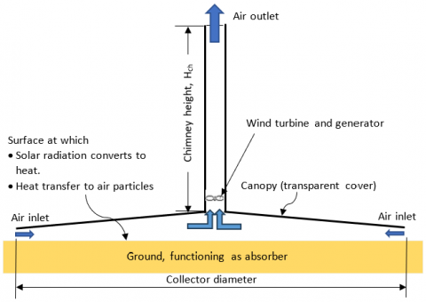
A schematic showing the components and operation principle of the solar chimney is presented in Figure 1. The operational principle is that the penetrated solar radiation through the transparent canopy reaches and heats the ground, which functions as the absorbing media of the collector. Heat transfers by convection from the heated ground to the air and is converted to kinetic energy that produces an air stream starting from the ambiance surrounding the collector. Then, the air moves inside the solar collector to the central zone and changes direction from radial flow to upward axial flow inside the chimney and exits from the chimney tower to the ambiance. The motion inside the chimney tower is maintained by the stack effect created by the air temperature difference across the SCPP [28].
Figure 1. Schematic diagram defining the fundamental concept of the solar chimney power plant
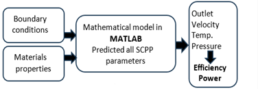
The conventional SCPP was analyzed, and all aerothermal parameters, power, and efficiency were calculated numerically utilizing a developed mathematical model coded in MATLAB. The hybrid SCPP model was developed utilizing CAD features. The analysis of the hybrid SCPP has been achieved by a combination of software, mathematical model and CFD simulation. Moreover, with the boundary conditions of Manzanares SCPP, ANSYS solved the conservation equations and produced the output parameters that allowed the prediction of the output power and efficiency. The outlines of the methodology structure are shown in Figure 2.
Many software has been used to achieve the objective, including:
i. MATLAB software is used for In-house developed code to simulate and solve the mathematical model of the conventional SCPP.
ii. CAD software to develop the models of the conventional and hybrid SCPP, which are then imported to ANSYS.
iii. RGAS software to determine the combustion properties of the flue gases.
iv. ANSYS software to solve the governing equation, simulate, and analyze the hybrid SCPP.
(a) Solar chimney power plant
(b) Hybrid solar chimney power plant
Figure 2. Simulation and analysis strategies
2.1 Mathematical analysis and model development
The objective of the mathematical model for SCPPs is to develop a set of equations and to solve these equations using numerical techniques by coding in MATLAB software. The mathematical model only considers solar mode, while the addition of the flue gases would be accomplished by the CFD simulation in ANSYS.
2.1.1 Assumptions
Solving the governing equations using numerical techniques requires certain assumptions. So, the following assumptions were made:
• The system is working in a steady state, and the solution is at pre-selected solar and ambient conditions.
• Air is an ideal gas, which is a valid assumption since the air temperature variation is less than 25℃ [29].
• The incompressible flow assumption is valid as the maximum Mach number does not reach the value of 0.1 [29].
• The air entering the collector is at ambient temperature and atmospheric pressure.
• The properties of air, like thermal conductivity, viscosity, and specific heat capacity, are evaluated in ambient conditions.
• Manzanares - Spain pilot plant dimensions have been adopted in the analysis, as shown in Table 1.
Table 1. Reference dimensions of Manzanares pilot plant dimensions [22]
|
Geometry |
Measure (m) |
|
Collector inlet radius, $R_{inlet}$ |
122 |
|
Collector outlet (= chimney inlet radius), $R_{ch, in}$ |
5.08 |
|
Canopy height at collector inlet, $H_{in}$ |
2 |
|
Canopy height at collector exit, $H_{out}$ |
6 |
|
Chimney height, $H_{ch}$ |
194.6 |
2.1.2 Heat transfer coefficients
The wind heat losses from the surface of the canopy to the ambient are dependent mainly on wind velocity and are determined by [26]:
$h_w=2.8+3.0 \times V_w$ (1)
where, hw is the wind heat loss coefficient, and Vw is the wind velocity in m/s obtained from the weather data.
The radiation heat transfer coefficient from ground to canopy, $h_{r, g-c}$ is:
$h_{r, g-c}=\frac{\sigma\left(T_g{ }^2+T_c{ }^2\right)\left(T_g+T_c\right)}{\frac{1}{\varepsilon_g}+\frac{1}{\varepsilon_c}-1}$ (2)
where, σ is Stefan Boltzmann constant, Tg and Tc are the ground and canopy temperatures, respectively. εg and εc are the ground and canopy emissivities, respectively.
The radiative heat transfer coefficient from canopy to ambient. $' h_{r, c-a m b}{ }^{\prime}$ is given by:
$h_{r, c-a m b}=\varepsilon_c \sigma\left(T_c{ }^2+T_{s k y}{ }^2\right)\left(T_c+T_{s k y}\right)$ (3)
where, Tsky and Tamb are the sky and ambient temperature, respectively, correlated as $T_{\text {sky }}=0.5552\left(T_{\text {amb }}\right)^{1.5}$.
The heat transfer coefficient from canopy to collector air, $h_{c, c-a i r}$ is [30]:
$h_{c, c-a i r}=\frac{0.2106+0.0026 V_{i n}\left\{\frac{T_m \rho}{\mu g\left(T_{f m}-T_c\right)}\right\}^{1 / 3}}{\left\{\frac{\mu T_m}{\left(T_{f m}-T_c\right) g \rho^2 C_p k^2}\right\}^{1 / 3}}$ (4)
where, g is gravitational acceleration, Tfm is the mean temperature of collector air, and Tm is the mean temperature of Tc and Tfm.
ρ, μ, k and $C_p$ represent the collector air density, dynamic viscosity, thermal conductivity, and specific heat capacity, respectively. They are all evaluated at the mean temperature of collector air.
Similarly, the heat transfer coefficient from ground to collector air, $h_{c, g-a i r}$, is calculated based on $T_g, T_{f m}$ and the physical properties of air [30]:
$h_{c, g-a i r}=\frac{0.2106+0.0026 V_{i n}\left\{\frac{T_m \rho}{\mu g\left(T_g-T_{f m}\right)}\right\}^{1 / 3}}{\left\{\frac{\mu T_m}{\left(T_g-T_{f m}\right) g \rho^2 C_p k^2}\right\}^{1 / 3}}$ (5)
The top loss coefficient, $U_t$, from the collector to the ambient is calculated by Duffie and Beckmann [31]:
$U_t=\left(\frac{1}{h_w+h_{r, c-a m b}}+\frac{1}{h_{r, q-c}+h_{c, q-a i r}}\right)^{-1}$ (6)
The bottom loss coefficient, $U_b$, (representing heat loss to ground layers) is given by the study [31]:
$U_b=\frac{k_{g r}}{d}$ (7)
where, $k_{g r}$ and $d$ refers to the thermal conductivity of ground material and depth, respectively.
The overall heat loss coefficient of the collector, $U_L$ is thus evaluated by Eq. (8) as:
$U_L=\frac{\left(U_b+U_t\right)\left(h_{c, c-a i r} h_{c, g-a i r}+h_{c, c-a i r} h_{r, g-c}+h_{r, g-c} h_{c, g-a i r}\right)+\left(h_{c, g-a i r}+h_{c, c-a i r}\right) U_b U_t}{h_{c, c-a i r} h_{r, g-c}+h_{r, g-c} h_{c, g-a i r}+h_{c, c-a i r} h_{c, g-a i r}+U_t h_{c, g-a i r}}$ (8)
The collector performance parameters, such as the collector efficiency factor, $F^{\prime}$, collector flow factor, $F^{\prime \prime}$, and collector heat removal factor, $F_R$, are based on the heat transfer coefficients discussed previously.
The collector efficiency factor, F' is given by:
$F^{\prime}\frac{h_{c, c-a i r} h_{r, g-c}+U_t h_{c, g-a i r}+h_{r, g-c} h_{c, g-a i r}+h_{c, c-a i r} h_{c, g-a i r}}{\left(U_t+h_{r, g-c}+h_{c, c-a i r}\right)\left(U_b+h_{r, g-c}+h_{c, g-a i r}\right)-\left(h_{r, g-c}\right)^2}$ (9)
The collector heat removal factor, $F_R$, is a quantity that relates the actual useful energy gain of a collector to the useful gain if the whole collector surface were at the fluid inlet temperature and is calculated as [31]:
$F_R=\frac{\dot{m} C_p}{A_{\text {coll }} U_L}\left[1-e^{\left(-\frac{A_{\text {coll }} U_L F^{\prime}}{\dot{m} C_p}\right)}\right]$ (10)
where, Acoll is the surface area of the collector, $A_{\text {coll }}=\pi\left(R_{\text {inlet }}^2-R_{c, \text { out }}^2\right)$. Rc,out is the inner radius of the collector, and Rinlet is the outer radius of the collector at the ambient air inlet.
The amount of solar energy absorbed by the collector, S, is dependent on the solar radiation falling on the canopy surface and calculated as:
$S=I_T(\tau \alpha)_{a v g}$ (11)
where, IT is the radiation incident on the tilted surface (canopy) and (τα)avgis the average transmissivity of the canopy material, multiplied by the absorptivity of ground material.
Thus, the useful energy gained by the collector, $Q_u$, is calculated as:
$\begin{gathered}Q_u=\left[F^{\prime}\left\{S-U_t\left(T_{f m}-T_{a m b}\right)-U_b\left(T_{f m}-T_g\right)\right\}\right] \cdot A_{\text {coll }}\end{gathered}$ (12)
2.1.3 Performance evaluation parameters
To find out the power output from the SCPP system, the air temperature at the collector outlet, $T_{c, \text { out }}$, or temperature rise, $\Delta T$, of the collector air must be known. Under steady conditions, the equations are simplified as:
$T_{c, \text { out }}=2 T_{f m}-T_{a m b}$ (13)
$\Delta T=T_{c, \text { out }}-T_{a m b}$ (14)
Once the temperature rise is found, the total kinetic energy in the air can be calculated. After absorbing energy inside the collector, the velocity of air increases. Theoretically, it is maximum at the base of the chimney and is evaluated by:
$V_{c h}=\sqrt{2 g H_{c h} \frac{\left(T_{c, \text { out }}-T_{a m b}\right)}{T_{a m b}}}$ (15)
where, $V_{c h}$ refers to the velocity of air at the inlet of the chimney, Hch is the chimney height, and g is the gravitational acceleration.
The total power of the moving air under no load condition (without turbine) is the product of the volumetric flow rate of air and total pressure difference (pressure difference between the chimney base and the ambient) [32]:
$P_{t o t}=\Delta p_{t o t} \cdot\left(V_{c h} \cdot A_{c h}\right)$ (16)
$\Delta p_{t o t}=g \cdot H_{c h} \cdot \rho_{i n} \cdot \frac{\left(T_{c, o u t}-T_{a m b}\right)}{T_{a m b}}$ (17)
where, Ptot is the total power contained in the working fluid, ∆ptot is the total pressure difference in the system, and Ach is the cross-sectional area of the chimney.
The actual maximum velocity at load must be computed to find the actual maximum power output from the SCPP system under load conditions (turbine installed). Ge and Ye [33] suggest that load velocity is equal to one-third of the theoretical maximum velocity.
$V_{c h}^{\prime}=\frac{1}{3} V_{c h}$ (18)
Thus, the power delivered to the grid is dependent on the load velocity of air, pressure difference in the system, chimney inlet area, turbine efficiency, and frictional loss factor:
$P_{n e t}=V_{c h}^{\prime} \cdot \Delta p_{t o t} \cdot A_{c h} \cdot \eta_t \cdot \eta_f$ (19)
where, $\eta_t$ represents the turbine efficiency, taken as 0.83 [29], and η is the overall friction loss factor, taken as 0.9 [34].
The overall efficiency of the SCPP system can be determined as:
$\eta_{plant}=\frac{P_{net}}{I_T \cdot A_{coll}}$ (20)
Several constant values and properties of materials in the set of Eqs. (1) to (20) of the mathematical model have been presented in section 2.3 of the method and materials.
2.2 Simulation of hybrid solar chimney/flue gas power plant
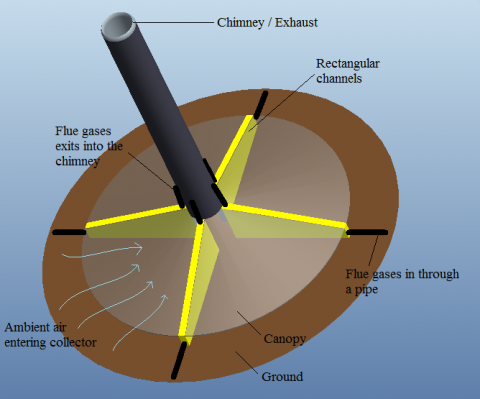
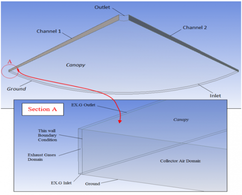
The fundamental idea of the proposed hybrid power plant is to utilize the wasted thermal energy in the exhaust of TPP in the SCPP. To utilize an external heat source inside the solar collector of the SCPP system, channels to carry exhaust gases were added to utilize the heat from the exhaust gases to elevate the temperature of the air collector. This possibility was adopted in this study with an initial suggestion of using four channels, as shown in Figure 3. This section supports the computational model development of the hybrid SCPP.
2.2.1 Design of the hot gas channels
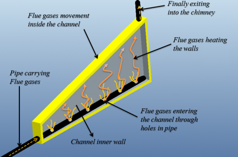
Exhaust gases enter the channel by means of an inlet pipe and are injected inside the channel through small holes. The pipe is illustrated on the inner lower surface of the channels. The channels are made by Carbon Steel, AISI 1010. They are hollow with rectangular cross-sections with inlet and outlet pipes connected to the channel, as shown in Figure 4. Exhaust gases are released from the pipe inside the channel through small holes. An exit pipe would carry the hot gases to the chimney.
Figure 3. Proposed design of SCPP integrated with a heat source, placement of four channels
Figure 4. Internal configuration of the flue channel and the supply of flue gas
These hot gases transfer energy to the channel walls through a convection heat transfer mechanism. The thermal energy of the hot gases starts moving outward from the channel. Heat is conducted within the thickness of the channel walls. Then, an external convection takes place between the external channel walls and the collector air. This addition of heat to the collector air causes its temperature to rise. It is worth mentioning that the length and height of the channel are as per the dimensions available under the canopy. The hot air inside the collector rushes toward the collector outlet due to temperature difference. Hence, the kinetic energy of the moving air increases depending on the temperature difference. Finally, the hot air enters the chimney base, where a turbine converts its kinetic energy into power. Flue gases from the channel are released into the chimney. The plants would be able to deliver power during night, cloudy or rainy weather conditions, also, it could be used as a standby power generating facility.
The computational simulation of the solar collector, including the flue channels, is based on the above-described fundamentals of the hybrid SCPP. However, to establish the computational model, the proposed hybrid SCPP integrated with TPP exhaust requires specific geometries that are based on real data. Various parameters related to the flue channel dimensions are given in Table 2.
Table 2. Flue channel's dimensions
|
Parameter |
Value |
|
Height at collector Inlet |
2.0 m |
|
Height at collector outlet |
6.0 m |
|
Wall thickness |
0.015 m |
|
Inner width |
0.17 m |
|
Length |
117.0 m |
A software named 'RGAS' was used to determine the combustion properties of flue gases. Further details about the gas property are available in Section 2.3.
2.2.2 Computational model generation and mesh independence check
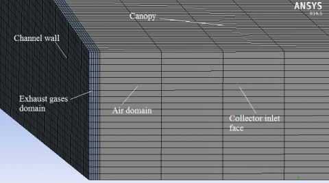
A CAD model of a collector with the Manzanares prototype dimensions was modeled using ANSYS Design Modeler, and its mesh was generated using the ANSYS Meshing module. The CAD model consisted of two fluid domains, i.e., collector air and exhaust gases, to simulate heat transfer from the exhaust gases to the air inside the collector. An isometric view of the mesh generated for the solar collector is shown in Figure 5, including the canopy cover meshing, half of the gas channel with gas domain and channel metal wall, and the collector air domain.
Figure 5. Isometric view of the generated mesh of the collector geometry
The mesh generated was a structured mesh consisting of hexahedral elements. Figure 6 shows the generated mesh. It is worth mentioning that thin wall boundary conditions separate the two fluid domains (exhaust gases and collector air). The selection criteria of the mesh were done by using the grid independence technique. Three similar meshes were tested consisting of 735,000, 925,000, and 1,231,200 elements, respectively. Simulations were run for each mesh. For instance, for the temperature parameter, the results were 320.88 K for 735,000 elements, 320.9 K for 925,000 elements, and 320.43 K for 1,231,200 elements. Finally, with the negligible effect of mesh density on the results, the mesh with the lowest elements was selected for further simulations to reduce the computational time.
Figure 6. Oriented view of mesh at the collector inlet section
2.2.3 Assumptions used in the computational procedure
The following assumptions were considered in proposing the SCPP system integration with the external heat source.
The exhaust gases are assumed to enter the inlet of the channels at 24.5 kg/s at 370℃ temperatures.
The mass flow rate of exhaust gases entering the channels is equally divided among the channels.
The exhaust gases' properties, like thermal conductivity, specific heat capacity, dynamic viscosity, density, etc., are evaluated at the gas turbine exit temperature.
The system is in a steady state.
The incompressible air flow assumption is valid as the maximum Mach number does not reach the value of 0.1 [29].
2.2.4 CFD governing equations
The CFD simulation considers the heat transfer and fluid flow process along the solar collector. The software solves the governing equations to describe the behavior of the fluid. The equations solved by ANSYS are the conservation of mass, momentum, and energy with the following forms.
Conservation of mass:
$\frac{\partial u}{\partial x}+\frac{\partial v}{\partial y}+\frac{\partial w}{\partial z}=0$ (21)
Conservation of momentum:
$\rho \frac{\partial u_i}{\partial x_i}=-\frac{\partial p}{\partial x}+\frac{\partial \tau_{x x}}{\partial x}+\frac{\partial \tau_{y x}}{\partial y}+\frac{\partial \tau_{z x}}{\partial z}+S_x$ (22)
$\rho \frac{\partial u_j}{\partial x_j}=-\frac{\partial p}{\partial y}+\frac{\partial \tau_{x y}}{\partial x}+\frac{\partial \tau_{y y}}{\partial y}+\frac{\partial \tau_{z y}}{\partial z}+S_y$ (23)
$\rho \frac{\partial u_k}{\partial x_k}=-\frac{\partial p}{\partial z}+\frac{\partial \tau_{x z}}{\partial x}+\frac{\partial \tau_{y z}}{\partial y}+\frac{\partial \tau_{z z}}{\partial z}+S_z$ (24)
Conservation of energy:
$\begin{aligned} & C_p \rho\left(\frac{\partial(u T)}{\partial x}+\frac{\partial(v T)}{\partial y}+\frac{\partial(w T)}{\partial z}\right) \quad=k\left(\frac{\partial^2 T}{\partial x^2}+\frac{\partial^2 T}{\partial y^2}+\frac{\partial^2 T}{\partial z^2}\right)+S_E\end{aligned}$ (25)
where, ui, uj, and uk are the velocity components in x, y, and z directions. The Boussinesq approximation is adopted in the set of momentum equations, which consider the buoyancy term by assuming the density as in Eq. (26).
$\rho=\rho_o(1-\beta \Delta T)$ (26)
The expansion coefficient, β is predicted as:
$\beta=-\frac{1}{\rho}\left(\frac{\delta \rho}{\delta T}\right)_p \approx-\frac{1}{\rho} \frac{\rho_0-\rho}{T_0-T}$ (27)
In this study, the RNG (k-ε) turbulence model was adopted. The turbulence kinetic energy, k, and its dissipation rate, ε, in the RNG model are calculated from the following transport equations [35].
$\begin{gathered}\rho \frac{\partial}{\partial x_i}\left(k u_i\right)=\frac{\partial}{\partial x_j}\left(\alpha_k \mu_{\mathrm{eff}} \frac{\partial k}{\partial x_j}\right)+G_k+G_b-\rho \varepsilon-Y_M+S_k\end{gathered}$ (28)
$\begin{aligned} \rho \frac{\partial}{\partial x_i}\left(\varepsilon u_i\right)=\frac{\partial}{\partial x_j} & \left(\alpha_{\varepsilon} \mu_{\mathrm{eff}} \frac{\partial \varepsilon}{\partial x_j}\right)+G_{1 \varepsilon} \frac{\varepsilon}{k}\left(G_k\right. \left.+C_{3 \varepsilon} G_b\right)-C_{2 \varepsilon} \rho \frac{\varepsilon^2}{k}-R_{\varepsilon}+S_{\varepsilon}\end{aligned}$ (29)
In the set of Eqs. (21) to (29), S represents the source term. Further terms and constants of the turbulence model can be found by Tukkee et al. [35, 36]. The Discrete Ordinates (DO) radiation model, available in the solar calculator in ANSYS Fluent, has been adopted to represent the solar radiation passing through the transparent Perspex to heat the air inside the collector.
To simplify the equations, the incompressible flow assumption is justified for the model since the maximum Mach number is much smaller than 0.1. The reference density is constant and substituted into the conservation of mass and energy equations. This model treats density as a constant value in all solved equations except for the buoyancy term in the momentum equation. This model accounts for the full buoyancy effect, where the density varies with temperature, and the flow is motivated by the force of gravity, which influences the change in density [29].
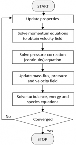
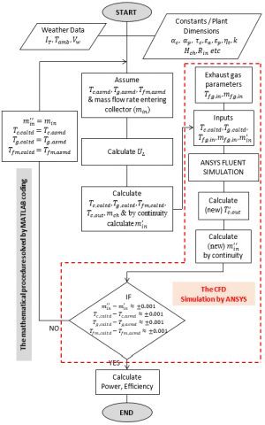
The solution was carried out using the semi-implicit method for the pressure-linked equations (SIMPLE) algorithm. It is a pressure-based segregated method that solves the governing equations sequentially to obtain a converged solution. Because the governing equations are non-linear and coupled, the solution loop must be carried out iteratively in order to obtain a converged numerical solution. The solution was deemed converged when all the residuals reached an accuracy of 10-5. Each iteration consists of the steps presented in Figure 7.
2.2.5 Simulation boundary conditions
The B.C.s, like inlet mass flow, canopy temperature, and ground temperature, used in mathematical and computational simulations were taken from the actual data of the Manzanares SCPP. This was done to have side by side comparison of results for the SCPP system running in solar mode and hybrid mode. The values of the B.C.s are shown in Table 3.
Furthermore, the boundary conditions of the exhaust gases from a gas turbine engine are also a high-temperature medium that can be used as a heat source. The exhaust gases from an industrial gas turbine have a temperature ranging typically from 350℃ to 650℃ [37, 38]. The usual exhaust gases are around 95 to 100 kg/s. In the current investigations, the utilized and recovered mass flow rate of the flue gas is 98 k/s at 370℃. Hence, there is 24.5 k/s in each one of the four gas channels.
Table 3. Boundary conditions adopted in the computational simulation of the hybrid SCPP
|
Boundary |
Type |
Condition |
|
Ground |
Wall |
Temperature, Tg,asmd= 330 K |
|
Collector |
Wall, semi-transparent |
Mixed |
|
Chimney |
Wall |
Adiabatic |
|
Collector inlet |
Pressure inlet |
Pgage= 0, Tamb = 307 K |
|
Chimney outlet |
Pressure outlet |
Pgage = 0, Tamb = 307 K |
Figure 7. Flowchart showing the steps followed in each iteration of the numerical solution
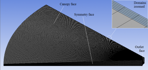
Figure 8. Isometric view of a quarter size of the collector between two channels
The collector is divided into four equal sections. One quarter with two exhaust gas channels was modeled. Two fluid domains, the exhaust gases domain and the collector air domain, were created. A thin wall boundary condition was used in replacement of the channel wall separating these domains. The thin wall boundary condition neglects the thickness of the wall and assumes the parameters on one side of the wall are exactly the same on the other side. The Isometric view of a quarter size of the collector between two channels is detailed in Figure 8, with the face's boundary condition selected for collector modeling with two channels. The upper and lower faces represent the canopy and ground, separated by two-channel walls. In section A of Figure 8, the terms' EX.G Outlet' and 'EX.G Inlet' represent the exhaust gases inlet and outlet faces in the channels, respectively.
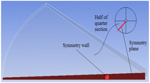
Asymmetry wall boundary condition was used which further halves the quarter collector section, thus reducing the simulation cost and time without compromising the solution with full section. Figure 9 shows a highlighted red face as the asymmetrical wall.
The simulation program for the integrated SCPP running on two energy inputs, i.e., solar energy and thermal energy of the flue gas, is described by the flow chart shown in Figure 10. The CFD simulation by ANSYS part, in the red bounded box, consists of the simulation of the collector with channels. This section in the chart is the only change after including the exhaust gas effect in the SCPP system.
Figure 9. Symmetry wall condition used in the collector modeling utilizing one-eighth of the collector size
Figure 10. The methodology flow chart displays the sequence of the simulation procedure of the hybrid solar chimney power plant integrated with exhaust gases of a thermal power plant
2.3 Materials of the plant's components
The materials specifications include construction materials and working fluid materials. The same material properties have been used in the mathematical model and CFD simulation. The construction materials required in the analysis of the SCPP and hybrid SCPP are the same, including the canopy cover of the collector, the ground, and the chimney. The material properties are shown in Table 4.
Table 4. Material properties of the system components for computational simulation
|
Physical Property |
Canopy |
Ground |
|
Material |
glass |
sandstone |
|
Absorption coefficient |
0.06 |
0.9 |
|
Transmission coefficient |
0.92 |
0 |
|
Density (kg/m3) |
2700 |
2320 |
|
Specific heat (J/kg‧K) |
840 |
780 |
|
Thermal conductivity (W/m‧K) |
0.78 |
3.5 |
|
Emissivity |
0.9 |
0.9 |
For the properties of the working fluid, an arbitrary gas turbine PP was selected, having its exhaust gas temperature, exhaust mass flow rate and fuel type as natural gas. A software named 'RGAS' was used to determine the combustion properties of flue gases. The temperature of the exhaust gases was entered to determine their various physical properties. The properties of exhaust gases at 643.15 K temperatures entering the channels are mentioned in Table 5 and were used as input in the setup of the CFD simulation.
Table 5. Exhaust gas properties calculated from RGAS Module [37, 38]
|
Parameter |
Value |
|
Fuel Type |
Natural Gas |
|
Temperature |
643.15 K |
|
Density |
0.53 kg/m3 |
|
Dynamic Viscosity |
2.9992e-5 Pa.s |
|
Thermal conductivity |
0.04909 W/m∙K |
|
Specific Heat Capacity |
1,126.8 J/kg∙K |
Two simulations were conducted in this study. The first is named solar mode, which means conventional SCPP without channels. The second is the hybrid mode, which means the case of four flue channels inserted in the system.
3.1 Solar mode
The simulation under this operational mode was conducted for 24 hours to count the actual operational case in the night without any input.
3.1.1 Collector components temperatures
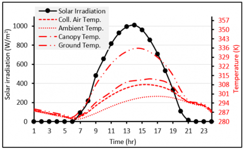
In the simulation of the system operation under solar mode, the SCPP system operates under solar energy input only. The results of this simulation were conducted using the mathematical model to verify the experimental results of the Manzanares prototype. Figure 11 shows the temperature trend of various collector components, such as canopy and ground. It is seen that the canopy and ground temperatures follow the same trend as that of the ambient air. The heat transfer process inside the collector results in components temperature being maximized between the peaks of solar radiation and ambient air temperature. It is also worth noting that during the night hours, all temperatures in connection to the collector become almost the same as the ambient temperature. This is due to the absence of solar radiation, whereas, during the day, temperatures increase with respect to solar intensity.
Figure 11. Updraft velocity, pressure difference, and power output as a function of temperature rise
3.1.2 Validation
A summarized comparison of simulated results with the Manzanares prototype is presented in Table 6. This validates the mathematical model with an error margin of 7% for updraft velocity, 0.3% for temperature rise, and 1.9% for power output.
Table 6. Comparison of the current simulation results with the Manzanares pilot SCPP
|
At Solar Irradiance of 1000 W/m2 |
Updraft Velocity at Chimney Base (m/s) |
Air Temperature Rise (ΔT) |
Output Power (kW) |
|
Manzanares Plant [39] |
15 |
20 |
50 |
|
Simulation Results |
16.05 |
20.06 |
49.04 |
|
Percentage of Error |
0.94% |
0.3% |
1.9% |
3.2 Results analysis of the hybrid mode
It is assumed that the supply of the flue gases inside the channels is controlled for equal distribution. Hence, there are 24.5 kg/s of flue gases with 370℃ injected inside each one of the four channels.
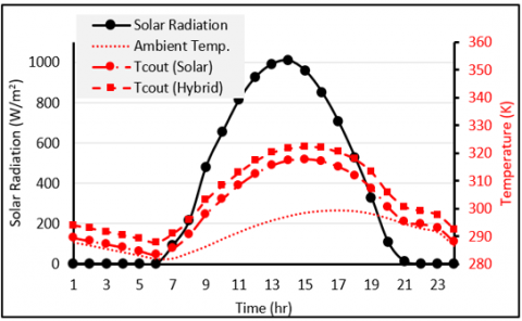
3.2.1 Collector air outlet temperature
The air temperature at the outlet of the collector is observed to be increased when using exhaust gases. Just like the mean air temperature, its influence is almost constant throughout the day, as illustrated in Figure 12. The important difference between the two operational modes is in the night hours until the next morning, i.e., from 09:00 PM till 06:00 AM. The air temperature at the outlet of the collector when the SCPP operates without flue gas is around 1.5 K above the ambient temperature. When the SCPP operates under the hybrid mode, the air outlet temperature is around 4 K. However, as an everyday average, the hybrid mode produces air temperature at the outlet of the collector around 4.5 K higher than the normal operational mode.
Figure 12. Comparison of collector outlet air temperature for conventional and hybrid modes
3.2.2 Output power comparison
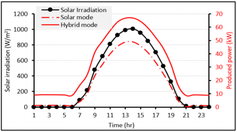
In the hybrid mode, due to an increase in the temperature rise of collector air, the performance of the SCPP system was also observed to increase. It was observed that power increases significantly during the daytime due to the effect of exhaust gases. Figure 13 shows an increase in power during the peak hour. During night hours, there is significant constant power output, enabling the plant for night operation, cancelling the present drawback of conventional SCPP technology. At the peak hour of 1000 W/m2 solar intensity, the comparison of output power for the two modes was 67 kW from the hybrid and 49.04 kW from the solar mode.
Figure 13. Comparison of power output for conventional and hybrid modes of SCPP with flue gas supply using four channels
The average output power delivered by the plant during nighttime for solar and hybrid modes was estimated to be 8.95 kW from hybrid mode and 1.07 kW from solar mode.
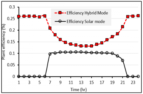
3.2.3 Plant efficiency comparison
With an increase in the overall performance of the SCPP system under hybrid mode, plant efficiency was also observed to increase using exhaust gas channels. The comparison of solar mode and hybrid mode plant efficiencies for a day is presented in Figure 14. There is a smooth drop in hybrid mode efficiency during the 7th hour compared to the sudden drop in solar mode. The reason for this smooth efficiency drop in hybrid mode is that the exhaust gases are still a dominant factor in the operation of the SCPP. An increase in the solar intensity changes the dominancy towards solar mode over hybrid mode. Hence, the variations in efficiency would keep on shifting the dominancy of the operational modes. During the night, in hybrid mode, the efficiency is constant because of constant plant power output due to the constant energy input from the exhaust gas channels. The plant efficiency is considerably low due to the very low chimney tower efficiency, as well as the turbine efficiency.
The mean plant efficiency over the day is around 0.233% for hybrid mode compared to 0.047% for the solar mode, demonstrating a mean daily efficiency improvement of 80% by using the external heat source.
Figure 14. Comparison of SCPP plant efficiency for solar and hybrid operational modes
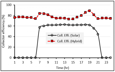
Figure 15 shows the predicted collector performance under solar mode and hybrid mode operations. The SCPP in the solar mode continues production after sunset till 09:00 PM, even without solar input, but there is a small amount of heat transfer from the hot ground to the flowing air inside the collector. However, after 09:00 PM, the production is steeply reduced and reaches zero output at 10:00 PM all night till 07:00 AM the next day. The collector efficiency is considerably increased, leading to a huge SCPP efficiency enhancement using an external heat source, as presented and discussed in the above Paragraph. The mean daily collector efficiency is around 34.3% under solar mode, while the mean daily efficiency is increased to around 78.5% under hybrid mode. The hybrid mode enhanced the mean daily collector efficiency by 56%.
Figure 15. Estimated collector efficiency under solar and hybrid modes operations
A hybrid solar chimney power plant is proposed and simulated through two interlinked analysis techniques. The hybrid system comprises of traditional solar chimney integrated with recovered thermal energy of exhaust gases of a thermal power plant. Two operational modes of the SCPP have been simulated and validated by comparison to Manzanares prototype data. The first mode is the normal operation of SCPP, named the solar mode, while the second mode is named hybrid mode, where four channels have been installed inside the collector and charged by flue gases of industrial gas turbine power plant. Results revealed that at the peak hour of 1000 W/m2 solar irradiation, power output increased to approximately 67 kW compared to 49.04 kW from solar mode, air updraft velocity at the chimney base increased to 17.76 m/s whereas solar mode delivered 16.05 m/s, and collector air temperature rise increased to 24.5 K compared to 20.06 K of the traditional SCPP. Hybrid mode simulations showed significant continuous plant operation, i.e., during nighttime, which mitigates one of the major drawbacks of traditional SCPPs. The enhanced mean daily efficiency of the plant and the collectors using the hybrid mode are around 80% and 56%, respectively.
It is recommended to extend the investigation by increasing the number of channels. In addition, the current study was limited by the solar collector alone, while the consideration of the entire plant components, including the turbine could present a more thorough understanding of the advantages and disadvantages of adding the flue gas channels.
The authors acknowledge Universiti Teknologi PETRONAS – Malaysia for the technical support, in particular the financial support under the Graduate Assistant Scheme (GA) provided to Dr. Azeem and Dr Ali.
|
Ach |
the cross-sectional area of the chimney |
|
Acoll |
the surface area of the collector |
|
Ain |
the inlet area of the collector |
|
Cp |
specific heat capacity of air |
|
d |
depth of ground |
|
E |
energy |
|
$\vec{F}$ |
external forces |
|
FR |
collector heat removal factor |
|
F' |
collector efficiency factor |
|
F'' |
collector flow factor |
|
g |
gravitational acceleration |
|
Hch |
height of chimney |
|
Hin |
height of canopy at collector inlet |
|
Hout |
height of canopy at collector outlet |
|
hc,c-air |
heat transfer coefficient from canopy to collector air |
|
hc,g-air |
heat transfer coefficient from ground to collector air |
|
hj |
specific enthalpy |
|
hr,c-amb |
radiative heat transfer coefficient from canopy to ambient |
|
hr,g-c |
radiation heat transfer coefficient from ground to canopy |
|
hw |
wind heat loss coefficient |
|
IT |
total radiation incident on a tilted flat surface |
|
k |
thermal conductivity of air |
|
kgr |
Thermal conductivity of ground material |
|
$\dot{m}_{c h}$ |
the mass flow rate in the chimney |
|
$\dot{m}_{in}$ |
the mass flow rate of air entering the collector |
|
$P_{n e t}$ |
net power output |
|
$P_{t o t}$ |
total power contained in the working fluid |
|
p |
pressure |
|
$p_{c h}$ |
pressure at the chimney base |
|
Qu |
useful energy gain by the collector |
|
Rch,in |
diameter of the chimney |
|
Rc,out |
the inner radius of the collector |
|
Rinlet |
outer radius of collector at the air inlet |
|
S |
solar energy absorbed by the collector |
|
Sh, Sm |
source terms |
|
Tamb |
ambient temperature |
|
Tc |
canopy temperature |
|
Tc,asmd |
initial value of canopy temperature |
|
Tc,caltd |
calculated temperature of canopy |
|
Tc,out |
temperature of air at the collector outlet |
|
Tfm |
the mean temperature of collector air |
|
Tfm,asmd |
initial value of collector air temperature |
|
Tfm,caltd |
calculated mean temperature of collector air |
|
Tg |
ground temperature |
|
Tg,asmd |
initial value of ground temperature |
|
Tg,caltd |
the calculated temperature of the ground |
|
Tsky |
temperature of the sky |
|
Ub |
bottom heat loss coefficient to ground layers |
|
UL |
overall heat loss coefficient of collector |
|
Ut |
Top heat loss coefficient from collector to ambient |
|
Vch |
the velocity of air at the inlet of the chimney (no load condition) |
|
$V_{c h}^{\prime}$ |
the velocity of air at the inlet of the chimney (load condition) |
|
Vin |
entering air velocity at collector inlet |
|
Vw |
wind velocity (weather data) |
|
$\vec{v}$ |
velocity vector |
|
Greek letters |
|
|
$\alpha_c$ |
absorptivity of canopy |
|
$\Delta p_{\text {tot }}$ |
the total pressure difference in the system |
|
$\Delta T$ |
collector air temperature rise |
|
$\varepsilon_c$ |
canopy emissivity |
|
$\varepsilon_g$ |
ground emissivity |
|
$\eta_f$ |
frictional loss factor |
|
$\eta_{plant}$ |
plant efficiency |
|
$\eta_t$ |
turbine efficiency |
|
$\mu$ |
dynamic viscosity of air |
|
$\rho$ |
density of air |
|
$\rho_{c h}$ |
density of air at the chimney base |
|
$\rho_{\text {in }}$ |
entering air density at ambient conditions at the collector inlet |
|
$\sigma$ |
Stefan Boltzmann constant |
|
$\overline{\bar{\tau}}$ |
stress tensor |
|
$(\tau \alpha)_{a v g}$ |
average transmissivity and absorbance product of canopy and ground materials |
|
Abbreviations |
|
|
CFD |
computational fluid dynamics |
|
DO |
discrete ordinates |
|
MW |
mega watt |
|
SCPP |
solar chimney power plant |
|
TES |
thermal energy storage |
|
TTP |
thermal power plant |
[1] Al-Kayiem, H.H., Aja, O.C. (2016). Historic and recent progress in solar chimney power plant enhancing technologies. Renewable, and Sustainable Energy Reviews, 58: 1269-1292. http://dx.doi.org/10.1016/j.rser.2015.12.331
[2] Aziz, A. (2011). Solar updraft tower. Schlaich Bergermann Solar GmbH, Stuttgart. https://www.academia.edu/13438380/Solar_Updraft_Tower_Project.
[3] Thomas, M.H., Davey, R.C. (2004). The solar tower: large-scale renewable energy power station development. In 19th World Energy Conference, Sydney, Australia.
[4] Schlaich, J., Bergermann, R., Schiel, W., Weinrebe, G. (2005). Design of commercial solar updraft tower systems - Utilization of solar-induced convective flows for power generation. Journal of Solar Energy Engineering, 127(1): 117-124. https://doi.org/10.1115/1.1823493
[5] Kreetz, H. (1997). Theoretische untersuchungen und auslegung eines temporären wasserspeichers für das Aufwindkraftwerk. Diploma Thesis, Technical University Berlin, Berlin. https://www.tu.berlin/en/evur/study-and-teaching/final-theses/completed-theses.
[6] Hammadi, D.S.H. (2008). Solar updraft tower power plant with thermal storage. Basrah Journal for Engineering Research. https://www.researchgate.net/publication/230851705_Solar_Updraft_Tower_Power_Plant_with_Thermal_Storage.
[7] Meng, F.L., Ming, T.Z., Pan, Y. (2011). A method of decreasing power output fluctuation of solar chimney power generating systems. 2011 Third International Conference on Measuring Technology and Mechatronics Automation, Shanghai, China, pp. 114-118. https://doi.org/10.1109/ICMTMA.2011.34
[8] Sharma, S.D., Kotani, H., Kaneko, Y., Yamanaka, T., Sagara, K. (2007). Design, development of a solar chimney with built-in latent heat storage material for natural ventilation. International Journal of Green Energy, 4(3): 313-324. https://doi.org/10.1080/15435070701332120
[9] Nia, E.S., Ghazikhani, M. (2024). Enhancing reliability and efficiency of solar chimney by phase change material integration: An experimental study. Thermal Science and Engineering Progress, 51: 102600. https://doi.org/10.1016/j.tsep.2024.102600
[10] Fu, C.F., Lu, M., Zhao, B. (2022). Integration of phase change thermal storage system with vertical solar chimney in the Greenhouse. Journal of Physics: Conference Series, 2467: 012021. https://doi.org/10.1088/1742-6596/2467/1/012021
[11] Ikhlef, K., Larbi, S., Üçgül, İ. (2022). Experimental study of different thermal storage system effects on the performance of a small prototype solar chimney power plant. Renewable Energy, 200: 516-526. https://doi.org/10.1016/j.renene.2022.09.087
[12] Al-Azawie, S.S., Hassan, S., Zammeri, M.F. (2014). Experimental and numerical study on ground material absorptivity for solar chimney power applications. WIT transactions on ecology and the environment, 186: 219-230. https://doi.org/10.2495/ESUS140191
[13] Al-Kayiem, H.H., Wahhab, H.A.A., Jamil, I.E.A., Mohamed, M.M., Mohamed, I.M. (2023). Evaluation of 15-m-height solar chimney model integrated with TES under tropical climate. International Journal of Energy Production and Management, 8(4): 211-218. https://doi.org/10.18280/ijepm.080402
[14] Ismaeel, A.A., Al-Kayiem, H.H., Baheta. A.T., Aurybi, M.A. (2016). Comparative critique of thermal energy storage technique in solar chimney power plants. International Energy Journal, 16: 11-24.
[15] Arefian, A., Hosseini-Abardeh, R., Rahimi-Larki, M., Torkfar, A., Sarlak, H. (2024). A comprehensive analysis of the time-dependent performance of a solar chimney power plant equipped with a thermal energy storage system. Renewable and Sustainable Energy Reviews, 189: 114051. https://doi.org/10.1016/j.rser.2023.114051
[16] Akbarzadeh, A., Johnson, P., Singh, R. (2009). Examining potential benefits of combining a chimney with a salinity gradient solar pond for production of power in salt affected areas. Solar Energy, 83(8): 1345-1359. https://doi.org/10.1016/j.solener.2009.02.010
[17] Hussain, A. (2007). Hybrid geothermal/solar energy technology for power generation. Higher Institute of Engineering. https://d3pcsg2wjq9izr.cloudfront.net/files/24847/articles/14612/hgst.pdf.
[18] Zandian, A., Ashjaee, M. (2013). The thermal efficiency improvement of a steam rankine cycle by innovative design of a hybrid cooling tower and a solar chimney concept'. Renewable Energy, 51: 465-473. https://doi.org/10.1016/j.renene.2012.09.051
[19] Hua, S., Leung, D.Y.C. (2017). Numerical modelling of the compressible airflow in a solar- waste heat chimney power plant. Energy Procedia, 142: 642-647. https://doi.org/10.1016/j.egypro.2017.12.106
[20] Al-Kayiem, H.H., Sing, C.Y., Yin. K.Y. (2012). Numerical simulation of solar chimney integrated with exhaust of thermal power plant. WIT transaction on Engineering Sciences, 75: 61-72. http://doi.org/10.2495/HT120061
[21] Islamuddin, A., Al-Kayiem, H.H., Gilani, S.I. (2013). Simulation of a collector using waste heat energy in a solar chimney power plant system. WIT Transaction on Ecology and the Environment, 179: 933-944. http://doi.org/10.2495/SC130792
[22] Chikere, A.O., Al-Kayiem, H.H., Karim, Z.A.A. (2011). Thermal field study and analysis in hybrid solar flue gas chimney power plant. In 2011 National Postgraduate Conference, Perak, Malaysia, pp. 1-6. https://doi.org/10.1109/NatPC.2011.6136401
[23] Chikere, A.O., Al-Kayiem, H.H., Karim, Z.A.A. (2011). Review on the enhancement techniques and introduction of an alternate enhancement technique of solar chimney power plant. Journal of Applied Sciences, 11(11): 1877-1884. http://doi.org/10.3923/jas.2011.1877.1884
[24] Al-Kayiem, H.H., Aurybi, M.A., Gilani, S.I.U., Ismaeel, A.A., Mohammad, S.T. (2019). Performance evaluation of hybrid solar chimney for uninterrupted power generation. Energy, 166: 490-505. https://doi.org/10.1016/j.energy.2018.10.115
[25] Lee, S.L. (2008). Energy recovery by conversion of thermal energy of flue gases to electricity. Undergraduate Thesis, Mechanical Engineering. Department, Universiti Teknologi PETRONAS, Malaysia.
[26] Chikere. A.O. (2014). Investigation on hybrid solar-flue gas chimney power plant. Ph.D. Thesis, Mechanical Engineering Department, Universiti Teknologi PETRONAS, 32610 Seri Iskandar, Malaysia. https://utpedia.utp.edu.my/id/eprint/25442/1/SUNDUS%20SAMEER%20JUMAAH_G02413.pdf.
[27] Jessam, R.A., Chua, H.J. (2023). Experimental evaluation of a hybrid inclined solar chimney for power generation. International Journal of Energy Production and Management, 8(2): 81-87. https://doi.org/10.18280/ijepm.080204
[28] Jessam, R.A., Al-Azawiey, S.S. (2023). Experimental and numerical investigation to correlate passage length and inclination to the performance of natural convective solar air heater. Journal of Engineering Science and Technology, 18(6): 3047-3061.
[29] Abdul Jamil, I.E., Al-Kayiem, H.H., Gilani, S.I.U. (2024). Experimental and numerical assessment of the influence of heat trap assembly on solar chimney performance. International Energy Journal, 109: 122-170.
[30] Bernardes, M.A.S., Von Backström, W., Kröger. D.G. (2009). Analysis of some available heat transfer coefficients applicable to solar chimney power plant collectors. Journal of Solar Energy, 83(2): 264-275. https://doi.org/10.1016/j.solener.2008.07.019
[31] Duffie, J.A., Beckman, W.A. (2013). Solar Engineering Thermal Processes. 4th edt. Wiley, New York, 2013.
[32] Moura, L.M., Strobel, C.S., Catapan, M.F. (2020). Technical feasibility analysis of the use of solar chimneys in Brazil. Revista Brasileira de Planejamento e Desenvolvimento, 9(3): 450-467. https://doi.org/10.3895/rbpd.v9n3.12636
[33] Ge, A.S., Ye, H. (2004). Solar chimney electric generating system and analysis of its intrinsic thermodynamic defect. Acta Energiae Solaris Sinica, 25(2) 263-268. https://scienceon.kisti.re.kr/srch/selectPORSrchArticle.do?cn=NART38158576.
[34] Zhou, X.P., Yang, J.K., Xiao, B., Hou, G.X. (2007). Simulation of a pilot solar chimney thermal power generating equipment'. Renewable Energy, 32(10): 1637-1644. https://doi.org/10.1016/j.renene.2006.07.008
[35] Tukkee, A.M., Ismaeel, A.A., Al-Kayiem, H.H. (2023). An assessment of the effects of the top cover plate material on the performance of the solar vortex engine. Journal of Engineering Science and Technology, 18(6): 3004-3017.
[36] Tukkee, A.M., Al-Kayiem, H.H., Gilani, S.I.(2023). Effect of density variation method and air humidity consideration on the computational simulation of solar vortex power generation systems. Thermal Science and Engineering Progress, 37: 101574. https://doi.org/10.1016/j.tsep.2022.101574
[37] Industrial Gas Turbines, 2012, SIEMENS Catalog. http://www.siemens.com/energy.
[38] Brooks, F.J. (n.d.). GE Gas Turbine performance characteristics. GE Power Systems, GER-3567H, Schenectady, New York. https://www.gevernova.com/content/dam/gepower-new/global/en_US/downloads/gas-new-site/resources/reference/ger-3567h-ge-gas-turbine-performance-characteristics.pdf.
[39] Haaf, W., Friedrich, K., Mayr, G., Schlaich, J. (1983). Solar chimneys part I: Principle and construction of the pilot plant in Manzanares. International Journal of Solar Energy, 2(1): 3-20. https://doi.org/10.1080/01425918308909911