Tsehaynesh Getu Abtew![]() | Ayodeji Olalekan Salau
| Ayodeji Olalekan Salau![]() | Habitamu Endalamaew Kassahun
| Habitamu Endalamaew Kassahun![]() | Elisha Didam Markus
| Elisha Didam Markus![]() | Joy Nnenna Eneh*
| Joy Nnenna Eneh*![]()
© 2025 The authors. This article is published by IIETA and is licensed under the CC BY 4.0 license (http://creativecommons.org/licenses/by/4.0/).
OPEN ACCESS
Brushless Direct Current (BLDC) motors are increasingly applied in medical devices, such as Continuous Positive Airway Pressure (CPAP) machines, which are the primary therapy for sleep apnea. This study introduces a novel sensorless BLDC motor control strategy for CPAP systems using a back-electromotive force (BEMF) observer to estimate motor speed, exploiting the direct relationship between rotor speed and BEMF magnitude. A key challenge in CPAP devices is that fluctuations in BLDC motor speed can lead to poor synchronization with patient breathing, causing inconsistent and uncomfortable airway pressure. To overcome this limitation, a fuzzy proportional-integral-derivative (FPID) controller is proposed. The FPID regulates the DC-link voltage based on the difference between the reference and estimated speed, and its output drives a hysteresis current-controlled DC-link voltage source inverter. MATLAB/Simulink simulations were carried out to assess the FPID controller against conventional approaches. The results show improved dynamic performance, with a rise time of 0.171 s and a settling time of 1.0055 s. Furthermore, the combination of hysteresis control and the BEMF observer ensures effective three-phase inverter switching, enhancing the reliability of CPAP motor control.
back-electromotive force (BEMF) observer, Continuous Positive Airway Pressure (CPAP) machines, fuzzy logic control, PID controller, sensor-less Brushless Direct Current (BLDC) motor
Brushless DC motors are widely utilized in present-day medical technologies. One important application is in the management of Obstructive Sleep Apnea (OSA), a common breathing disorder marked by recurrent blockage of the upper airway during sleep. This condition often results in disrupted sleep patterns and reduced oxygen levels. The most established treatment for OSA is Continuous Positive Airway Pressure (CPAP) therapy, which maintains airway patency by supplying a steady flow of pressurized air. The core component of a CPAP device is a blower system powered by a motor that precisely regulates airflow delivery to the patient. Among various motor types, Brushless Direct Current (BLDC) motors are increasingly favored in sleep apnea devices due to their high efficiency, compact size, low noise operation, and excellent controllability. Maintaining a consistent and accurate airflow rate is crucial for the effectiveness and patient comfort of CPAP therapy. Fluctuations in airflow can lead to inadequate pressure support, compromising treatment efficacy, or excessive pressure, causing discomfort and potentially disrupting sleep. Therefore, a robust and responsive speed control system for the BLDC motor driving the blower is essential [1-3].
In brushless DC (BLDC) motors, Hall-effect sensors are commonly employed to detect rotor position and regulate the motor drive. An alternative approach eliminates these sensors by relying on the monitoring of the motor’s back electromotive force (BEMF) for control. This sensorless configuration can lower overall system costs, which is one of the reasons BLDC motors are increasingly favored in medical device applications [4].
Lowering the airflow and enabling the patient to release their breath. Blower fans can benefit greatly from sensorless BLDC motors and drives. BLDC motors also have the benefit of being silent. Motors in medical equipment and patient care facilities must be silent in order to comply with low-noise rules. Given that the patient's bedroom at home is where the sleep apnea equipment is located, motors must adhere to considerably lower noise level guidelines despite operating at high speeds. As a result, BLDC motors eliminate a further source of motor noise by not having commutators or brushes [5-7]. A voltage across the winding of this motor causes it to rotate. The rotor's revolution through the motor's magnetic field produces the BEMF, or voltage generation. According to Lenz's Law, the magnetic flux that propels the rotor is opposed by a second magnetic field produced by the BEMF. Any motor has a fixed number of windings and magnetic flux. Nonetheless, the EMF produced is directly correlated with the rotor's angular speed. Therefore, changing the EMF value produced can change the speed of the rotor [7-9].
The result shows that fuzzy proportional-integral-derivative (PID) regulates speed. When it comes to speed and current dynamic performance, this controller performs better than a PID controller. A BLDC motor inverter drive based on a hysteresis band limit and a voltage source inverter drive is also completed. As a result, hysteresis current-based inverter drivers produce fewer current harmonics. The dynamics of BLDC motors and continuous positive airway pressure machines are modeled mathematically. Speed control allows the device to adjust the motor's speed to reach and hold the target pressure. Fluctuations in motor speed would lead to fluctuations in the delivered pressure, potentially rendering the therapy ineffective (if the pressure is too low) or uncomfortable and disruptive (if the pressure is too high). MATLAB software is used to design and simulate the linear and nonlinear model of the BLDC motor drive for the use of CPAP devices.
Extensive research has been conducted on determining the appropriate constant pressure settings for sleep apnea devices. Among the different electric drive technologies, brushless DC (BLDC) motor drives are considered highly efficient. However, achieving precise speed control remains challenging due to the nonlinear interaction between rotor speed and winding currents.
Saleh and Obed [2] investigated the use of a fractional-order controller in comparison with conventional approaches. Their study demonstrated that a fractional-order proportional–integral–derivative (PID) controller offers higher accuracy and improved reliability. In their design, the controller parameters—including proportional gain, derivative gain, integral gain, and fractional integral order were optimized using a genetic algorithm, with the Integral Time Absolute Error (ITAE) criterion serving as the optimization objective. To address sensorless position control in BLDC motors used in continuous positive airway pressure (CPAP) machines, Meenu and Hariharan [10] proposed a back electromotive force (BEMF) difference estimation method. In this approach, a closed-loop speed control system is implemented by generating an error signal from the difference between the actual motor speed and the desired reference speed.
Kaloi et al. [11] introduced a hybrid fuzzy-PID controller that integrates the strengths of classical PID control with fuzzy logic. Under steady-state or slowly varying operating conditions, both PID and fuzzy controllers provided satisfactory tracking performance. However, during sudden changes in load or set point, the PID controller exhibited significant overshoot. In contrast, the fuzzy-based approach effectively minimized overshoot while maintaining faster rise times, though this slightly extended the overall response time.
Khubalkar et al. [12] achieved permanent magnet brushless DC motor speed control using fractional order PID controller design and tuning. An expansion that gives the system greater flexibility and resilience is the fractional-order PID controller, which has five independent parameters.
Li et al. [13] achieved a high dependability, a wide speed range, and quickness as criteria for the sensorless high-speed brushless DC motor control that is implemented for the molecular pump. The pump must run at high speed for an extended period of time. The molecular pump's sensorless BLDC motor control system is created, and the motor position data is obtained using the back-EMF zero-crossing detection method. BEMF zero crossing does not employ motor speed control methods and only detects high speeds; it is unable to detect low speeds.
3.1 Model of CPAP machine
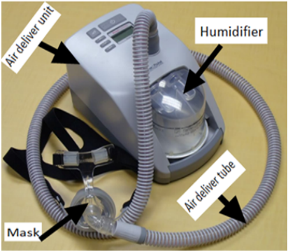
The treatment for sleep apnea involves using a CPAP machine. For a relatively low risk way of treating symptoms in a critical disease, CPAP is an option if tolerated. CPAP machines are commonly used by patients who experience breathing difficulties during sleep. These machines use modest air pressure to maintain open airways. Figures 1 and 2 depict a block diagram and a 3D picture depiction of the CPAP machine, respectively [10, 14].
Figure 1. CPAP Machine representation
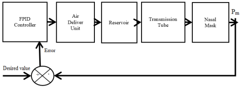
Figure 2. CPAP system model block diagram
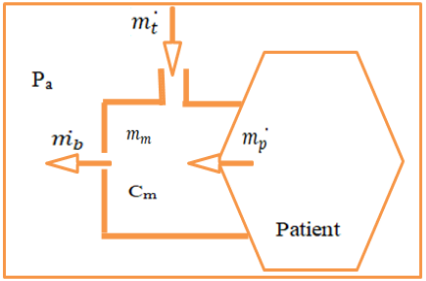
To apply mathematical models based on the following assumptions to every part of a CPAP machine. The extremely low-pressure variation seen leads to the assumption that the process is isothermal, disregarding variations in the air's characteristics, applying the principle of mass conservation across the reservoir. Figure 2 presents the block diagram of the CPAP system model.
3.1.1 Air Deliver Unit (ADU)
After comparing the output signal from the mask pressure (Pm) to the intended value (DV), the ADU controller performs the required actions to keep the mask air pressure constant.
3.1.2 Reservoir
The primary function of the reservoir is to lubricate the air entering the mask, preventing the patient's throat from becoming dry and uncomfortable.
$\left(\dot{m}_c-\dot{m}_t\right) d t=d m_t$ (1)
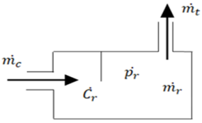
where, $\dot{m}_c-\dot{m}_{i n}$ denotes the air flow rate entering the reservoir; $\dot{m}_t-\dot{m}_{\text {out}}$ means the air out flow the tube; $d m_t-$ presents the change of air from the reservoir. The schematic representation of reservoirs is shown in Figure 3.
Figure 3. Schematic representation of reservoirs
Use the state equation to ascertain the rate of change of the air mass within the reservoir [10]:
$P_t V_t=m_r R_a T_r$ (2)
Take consider in constant temperature and volume results:
$\frac{d m_r}{d t}=\frac{V_r}{R_a T_r} \frac{d p_r}{d t}$ (3)
The following expression relates reservoir mass flow and pressure when Eq. (2) is substituted into Eq. (3):
$\left(\dot{m}_c-\dot{m}_t\right)=\frac{C_r d p_t}{d t}$ (4)
where, $C_r=\frac{V_r}{R_a T_r}$.
$\left(\dot{m}_c-\dot{m}_t\right)=\frac{C_r d p_t}{d t}$ (5)
where, $\dot{m}_c$ is the air flow rate entering the reservoir; $\dot{m}_t$ is the air out flow the tube.
3.1.3 Transmission tube
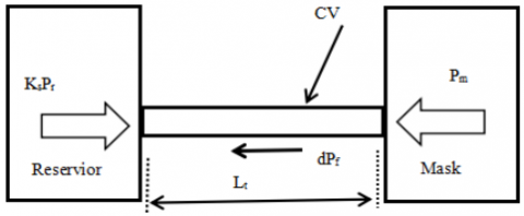
Because of the high peak air velocity encountered, it is essential to consider both the air inertia and shearflow resistance occurring within its internal diameter transmission tube. Figure 4 shows the schematic representation of the air transmission tube.
Figure 4. Schematic representation of air transmission tube
The pressure and friction forces are the two main forces depicted in the air transmission tube in Figure 4 that surround the air inside the tube. When applied throughout the control volume, Newton's second law produces:
$\left(K_s P_r-P_m\right) A_t-d p_f A_t=\rho A_t L_t \frac{d V_t}{d t}$ (6)
where, $K_s-$ reservoir contraction shock loss; $P_r-$ reservoir pressure; $P_m-$ mask pressure; $A_t-$ tube across section area; $d p_f-$ air shear resistance force; $\rho-$ air density; $L_t-$ tubelength; $V_t-$ air velocity with in tube.
The following formula can be used to calculate the pressure loss (dpf) caused by air-tube wall shear forces:
$d P_f=\rho g h_f=\frac{\rho f L_t V_t^2}{2 d t}$ (7)
where, $V_t=\frac{\dot{m}_t}{\rho A_t}$.
The shear forces dPf in terms of the slope R and intercept Y are expressed as follows using the linearized transmission tube airflow characteristics:
$d P_f=R_m \dot{m}_t+Y_m$ (8)
where, the tube air pressure drop's air mass flow base is indicated by the subscript m.
This pressure drop can alternatively be expressed as the pressure differential felt at the tube's ends, as seen in Figure 4 and expressed as:
$d P_f=K_s P_r-P_m$ (9)
The combination of Eqs. (8) and (9) permits the air mass flow rate inside the tube to be described in terms of the air pressure felt at each end of the tube and the linearized resistance, specifically:
$\dot{m}_t=\frac{K_s P_r-P_m-Y_m}{R_m}$ (10)
$\dot{m}_c-\frac{K_s P_r-P_m-Y_m}{R_m}=C_r \frac{d P_r}{d t}$ (11)
Arranging Eq. (11) provides the reservoir pressure (Pr) for the breathing system model expression:
$\frac{P_r}{\dot{\mathrm{~m}}_c+\frac{P_m}{R_m}+\frac{Y_m}{R_m}}=\frac{\frac{R_m}{K_s}}{\frac{R_m}{K_s}\left(C_r D+1\right)}$ (12)
where, $D=\frac{d}{d t}$.
The combination of Eqs. (11) and (12) leads to:
$K_s P_r-P_m-\left(R_v+Y_v\right)=\rho L_t \frac{d V_t}{d t}$ (13)
Arranging of Eq. (13) provides an expression that can be utilized in the breathing system model for tube air velocity (Vt):
$\frac{V_t}{\left(K_s P_r-P_m-Y_v\right)}=\frac{\frac{1}{R_v}}{\frac{\rho L_t}{R_v} D+1}$ (14)
where, $K_s-$ reservoir contraction shockloss; $P_r-$ reservoir pressure; $P_m-$ mask pressure; $L_t-$ tube length; $R_V-$ gradient of tube velocity pressure drop; $Y_v-$ Tube pressure drop velocity linear; $V_t-$ Air velocity within the tube.
3.1.4 Mask
In order to ensure that the patient is always breathing in fresh air, they are provided oxygen through a nasal mask in Figure 5 that is continually purged through eight tiny vents.
Figure 5. Schematic representation of nasal mask
$\left(\dot{m}_t+\dot{m}_p-\dot{m}_b\right) d t=d m_m$ (15)
In this case, the air mass flow rates entering the tube and leaving the mask vents are denoted by $\dot{m}_t$ and $\dot{m}_b$ respectively. The mass of air within the mask and the patient's breathing airflow rate are represented by $\dot{m}_p$ and $m_m$ When the rate of change of air mass inside the mask is calculated using the equation of state, the following happens:
$P_m V_m=m_m R_a T_m$ (16)
Suppose both temperature and volume remain constant in:
$\frac{d m_m}{d t}=\frac{V_m}{R_a T_m} \frac{d P_m}{d t}$ (17)
Substituting Eq. (9) in to Eq. (6) results in:
$\dot{m}_t-\dot{m}_b+\dot{m}_p=C_m \frac{d P_m}{d t}$ (18)
where, mask capacitance $\left(C_m\right)=\frac{V_m}{R_a T_m}$.
It is challenging to calculate the nasal mask vent flow discharge coefficient (Cd) accurately because the eight vent holes physically resemble a combination of an abrupt expansion into open space and a sharply edged orifice.
$P_m-P_a=\frac{\rho}{2 C_d^2 A_b^2} Q_b^2$ (19)
where, $\rho$ is air density within the mask; $A_b-$ minimum area of bias vent hole; $C_d-$ discharge coefficient; $Q_b-$ vent volume flow rate; $Q_b$ is expressed as: $Q_b=\frac{\dot{m_b}}{\rho n}$.
$P_m-P_a=\frac{\dot{m_b^2}}{2 C_d^2 A_b^2 \rho n^2}$ (20)
Now, the mask vent bias flow can be shown as follows:
$\dot{m}_t-\left[\frac{P_m+P_a+Y_b}{R_b}\right]+\dot{m}_p=C_m D P_m$ (21)
Put the expression for inhaling nasal mask pressure in Eq. (1).
$\frac{\mathrm{p}_{\mathrm{m}}}{\frac{P_a}{R_b}+\frac{Y_b}{R_b}+\dot{m}_t+\dot{m}_p}=\frac{R_b}{R_b C_m D+1}$ (22)
where, $R_b-$ gradient of mask bias vent model; $\mathrm{Y}_{\mathrm{b}}-$ mask bias flow linear model; $C_m-$ mask capacitance and $\mathrm{P}_{\mathrm{a}}-$ atmospheric pressure.
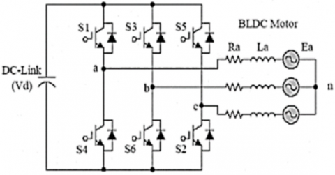
3.2 Mathematical modeling of brushless DC motor
Figure 6 illustrates the equivalent circuit of the specified phase for applying Kirchhoff's law to the three-phase star connected BLDC motor under consideration for the sensor less control model [15, 16].
Figure 6. Winding of BLDC motor with stator linked to three-phase circuit
$\begin{aligned} & V_{a n}=R_s i_a+L a \frac{d_{i a}}{d t}+L_{a b} \frac{d_{i b}}{d t}+L_{a c} \frac{d_{i c}}{d t}+e_a \\ & V_{b n}=R_s i_b+L b \frac{d_{i b}}{d t}+L_{b a} \frac{d_{i a}}{d t}+L_{b c} \frac{d_{i c}}{d t}+e_b \\ & V_{c n}=R_s i_c+L c \frac{d_{i c}}{d t}+L_{c a} \frac{d_{i a}}{d t}+L_{c b} \frac{d_{i b}}{d t}+e_c\end{aligned}$ (23)
All of the windings are supposed to have an equal resistance. Furthermore, it is assumed that if the lack of a conspicuous rotor results in no fluctuation in the rotor reluctance with angle:
$\begin{gathered}L_a=L_b=L_c=L \\ L_{a b}=L_{a c}=L_{b a}=L_{b c}=L_{c a}=L_{c b}=M\end{gathered}$ (24)
The variables Rs, L, and M represent the stator resistance, self-inductance, and mutual inductance, respectively, for each phase. It is believed that the stator phase star connection currents are balanced.
$i_a+i_b+i_c=0$ (25)
Eq. (25) is rearranged, and multiplying both sides by M yields:
$\begin{gathered}i_a+i_b=-i_c \\ M i_a+M i_b=-M i_c\end{gathered}$ (26)
From Eqs. (23) and (24):
$\begin{gathered}V_{a n}=R_s i_a+L \frac{d_{i a}}{d t}+M \frac{d_{i b}}{d t}+M \frac{d_{i c}}{d t}+e_a \\ V_{a n}=R_s i_a+L \frac{d_{i a}}{d t}+\frac{d}{d t}\left(M i_b+M i_c\right)+e_a\end{gathered}$ (27)
Substituting Eq. (26) into Eq. (27) gives Eq. (28):
$\begin{aligned} & V_{a n}=R_s i_a+L \frac{d i_a}{d t}+\frac{d}{d t}\left(-M i_a\right)+e_a \\ & V_{a n}=R_s i_a+L \frac{d i_a}{d t}+\frac{d}{d t}\left(-M i_a\right)+e_a\end{aligned}$ (28)
Given the motor armature specifications and the BEMF motor voltage, the per-phase terminal voltage is as follows:
$\begin{gathered}V_{a n}=R_s i_a+(L+M) \frac{d i_a}{d t}+e_a \\ L-M=L_S\end{gathered}$ (29)
where, L is phase inductance, M is mutual inductance, LS is self-inductance. Substituting Eq. (29) into Eq. (28) gives Eq. (30):
$V_{a n}=R_s i_a+L_s \frac{d i_a}{d t}$ (30)
In a similar way, the other phase voltage equations are obtained:
$V_{b n}=R_s i_b+L s \frac{d i_b}{d t}+e_b, V_{c n}=R_s i_c+L s \frac{d i_c}{d t}+e_c$
$\begin{aligned} & \frac{d i_a}{d t}=\frac{V_{a n}}{L_s}-\frac{R_s i_a}{L_s}-\frac{e_a}{L_s} \\ & \frac{d i_b}{d t}=\frac{V_{b n}}{L_s}-\frac{R_s i_b}{L_s}-\frac{e_b}{L_s} \\ & \frac{d i_c}{d t}=\frac{V_{c n}}{L_s}-\frac{R_s i_c}{L_s}-\frac{e_c}{L_s}\end{aligned}$ (31)
The three-phase BLDC motor BEMF can be formulated:
$e(t) m i=\frac{d \lambda_{m i}}{d x}$ (32)
The expression of the BEMF response from the three-phase power supply is given in Eq. (33):
$\left[\begin{array}{c}e_{m a} \\ e_{m b} \\ e_m\end{array}\right]=K_e \omega_m\left[\begin{array}{c}\sin \left(\theta_r\right) \\ \sin \left(\theta_r-\partial\right) \\ \sin \left(\theta_r-2 \partial\right)\end{array}\right]$ (33)
The BEMF is replaced by 120 electrical degrees from one phase to others, the induced BEMF depends on the rotor position and can be given as follows:
$\begin{gathered}e_a=K_e \omega_m\left(f\left(\theta_\gamma\right)\right) \\ e_b=K_e \omega_m\left(f\left(\theta_r-\partial\right)\right) \\ e_c=K_e \omega_m\left(f\left(\theta_r-2 \partial\right)\right)\end{gathered}$ (34)
where, $\omega_m-$mechanical rotor speed ($\mathrm{rad} / \mathrm{sec}$); $\mathrm{K}_e-$back-emf constant (v/rad.s-1); $\mathrm{f}\left(\theta_\gamma\right)-$trapezoidal function; $\theta_\gamma-$electrical angle of the rotor; $\mathrm{f}\left(\theta_\gamma\right)=\sin \left(\theta_\gamma\right), \mathrm{f}\left(\theta_\gamma\right)-$ trapezoidal function.
The combine product of the three phase BEMF and current known as the electromagnetic power, determine the amount of power sent to the rotor. That is
$P_{\text {mech }}=e_a i_a+e_b i_b+e_c i_c$ (35)
The three phase BLDC motor in Newton's has a defined electromagnetic torque.
$\begin{gathered}T_e=\frac{e_a i_a+e_b i_b+e_c i_c}{\omega_m} \\ T_e=\frac{P}{2}\left(\frac{e_a i_a+e_b i_b+e_c i_c}{\omega_m}\right) \omega_m \\ T_e=\frac{P}{2}\left(e_a i_a+e_b i_b+e_c i_c\right) \\ T_e=\frac{J d \omega_m}{d t}+B \omega_m+T_L\end{gathered}$ (36)
$\frac{d \omega_m}{d t}=\frac{1}{J}\left(T_e+T_L+B \omega_M\right)$ (37)
where, $J-$ inertia of the rotor coupled shaft $\left[\mathrm{kg} . \mathrm{m}^2\right] ; B-$ friction constant $\left[\mathrm{Nm} \cdot \mathrm{rad}^{-1}\right] ; T_L-$ Load torque $[\mathrm{Nm}] ; \omega_m-$ Mechanical rotor speed [rad.sec ${ }^{-1}$].
$\theta_\gamma=\frac{P \theta_m}{2} \omega_m=\frac{d \theta_m}{d t}$ (38)
One of the key ideas in control theory is the transfer function, and mathematical models based on this concept are frequently employed in the domain of automatic control. For the purpose of the motor's control design and performance analysis, the BLDC motor's transfer function is important. Because the BEMF generated at each stator-winding phase is directly correlated with the rotor speed, it may be expressed as follows:
$e_a=K_e \omega_m$ (39)
The applied stator phase current and the electrical torque generated are also directly correlated, and are expressed as follows:
$T_e=K_t i_a$ (40)
From Eqs. (31) and (30)
$\frac{d i_a}{d t}=\frac{V_{a n}}{L_s}-\frac{R_s i_a}{L_s}-\frac{e_a}{L_s}$ (41)
where, Ke is the BEMF constant, Kt is the torque constant, and Van is the stator phase winding voltage, ia is the stator phase winding current, and ean is the BEMF generated in the phase a winding.
$\begin{gathered}\frac{d i_a}{d t}=\frac{V_{a n}}{L_s}-\frac{R_s i_a}{L_s}-\frac{K_e \omega_m}{L_s} \\ \frac{d \omega_m}{d t}=\frac{1}{J}\left(T_e+T_L+B \omega_M\right)\end{gathered}$ (42)
where, $\omega_m$ is the motor's angular speed, $T_e$ is the electrical torque the motor produces, $J$ is its moment of inertia, $B$ is the air gap friction constant, and $T_L$ is the claimed load torque applied.
$\frac{d \omega_m}{d t}=\frac{1}{J}\left(K_t i_a+T_L+B \omega_M\right)$ (43)
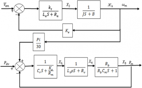
As an external factor, the load torque ($T_L$) is not calculated using the Laplace transform of the electromagnetic torque with zero initial conditions in Eq. (43). Figure 7 shows the overall CPAP machine and BLDC motor system state space equation based on each component in series connection.
Figure 7. Mathematical model represented by state space model
To design generally modeling of breathing system with BLDC motor in series connection a combination of each Eqs. (44)-(47).
$G_1(s)=P_r=\frac{1}{C_r S+\frac{K_S}{R_m}}$ (44)
$G_2(s)=V_t=\frac{1}{L_t \rho S+R_v}$ (45)
$G_3(s)=P_m=\frac{R_b}{R_b C_m S+1}$ (46)
$G_4(s)=\omega_m=\frac{K_t}{S^2 J L_s+\left(B L_s+R_s J\right) S+\left(B R_s+K_e K_t\right)}$ (47)
The transfer function of each component’s equation is taken as G1(s), G2(s), G3(s), and G4(s) respectively. to compute the transfer function throughout the system using the equations for each component model. Use the standard value of each component in the specification parameters to replace the parameter values. Each transfer function's combination:
$G(s)=G_1(s)+G_2(s)+G_3(s)+G_4(s)$
The Nyquist stability criterion and bode diagram can be used to see how stable the system is because closed loop poles are crucial to the system's transient response.
Otherwise, the state and output equations can be rewritten in the conventional vector-matrix form by using state space and the inverse Laplace transforms of the previous five equations.
$\left[\begin{array}{l}\dot{X}_1 \\ \dot{X}_2 \\ \dot{X}_3 \\ \dot{X}_4 \\ \dot{X}_5\end{array}\right]=\left[\begin{array}{ccccc}-\frac{B}{J} & \frac{1}{J} & 0 & 0 & 0 \\ -\frac{K_e K_t}{L_s} & -\frac{R_s}{L_s} & 0 & 0 & 0 \\ 0 & 0 & -\frac{1}{R_b C_m} & \frac{1}{C_m} & 0 \\ 0 & 0 & 0 &-\frac{R_v}{L_t \rho} & \frac{1}{L_t \rho} \\ -\frac{p i}{30} & 0 & -\frac{1}{C_r} & 0 & -\frac{K_s}{R_m C_r} \end{array}\right]\left[\begin{array}{l}X_1 \\ X_2 \\ X_3 \\ X_4 \\ X_5\end{array}\right]+\left[\begin{array}{cc}0 & 0 \\ K_t & 0 \\ \overline{L_s} & 0 \\ 0 & 0 \\ 0 & 1 \\ 0 & \overline{C_r}\end{array}\right]\left[\begin{array}{l}V_{a n} \\ P_{d v}\end{array}\right]$ (48)
$\left[\begin{array}{l}\omega_m \\ P_m\end{array}\right]=\left[\begin{array}{l}10000 \\ 00100\end{array}\right]\left[\begin{array}{l}X_1 \\ X_2 \\ X_3 \\ X_4 \\ X_5\end{array}\right]$ (49)
3.3 Sensorless control of brushless DC motor
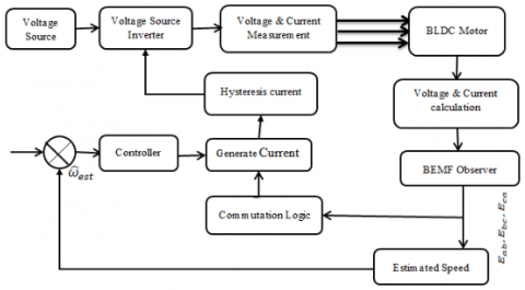
This section outlines the control approach for the brushless DC (BLDC) motor, with emphasis on rotor position and parameter estimation using a back electromotive force (BEMF) observer. The method leverages the trapezoidal nature of the BEMF waveform in BLDC machines to determine rotor position indirectly. Since the BEMF cannot be measured directly, it is estimated through an unknown input observer (UIO). In this framework, the BEMF is treated as both an unknown input and a state variable within the BLDC drive system. The initial line-to-line BEMF estimation is achieved using the UIO, which relies on the dc-link voltage and inverter switching signals. Alternatively, indirect estimation methods employ commutation functions to approximate BEMF. For clarity, a block diagram of the proposed system configuration is presented, illustrating how rotor speed and BEMF estimates are incorporated into the speed control loop of the BLDC motor (Figure 8).
Figure 8. General block diagram of controller of BLDC motor
3.4 Three-phase BLDC motor with sensor less control using BEMF
The back electromotive force (BEMF)-based strategy is currently one of the most advanced and widely adopted approaches for sensorless control of BLDC motors. In this method, commutation signals are obtained from the zero-crossing points of the BEMF, introducing a 30° electrical angle delay in rotor position detection. A common implementation relies on a logical switching circuit that processes the six position-dependent signals derived from the motor phases. Among the simplest techniques for BEMF estimation is the open-phase voltage sensing method, which identifies the zero-crossing instant of the non-energized phase to infer rotor position indirectly.
3.4.1 Using the unknown input observer, the first line-to-line BEMF
The first line-to-line BEMF current equation provides a mathematical relationship within the BLDC motor's electrical circuit. The Unknown Input Observer utilizes this equation, along with measured voltages and currents, to estimate the unknown line-to-line BEMF, which in turn allows for the inference of the rotor's position and speed for sensorless control. This avoids the need for physical sensors, reducing cost and complexity. The unknown input observer estimation is therefore taken into consideration in the following line-to-line equation [11].
$\frac{d i_{a b}}{d t}=-\frac{2 R_s}{2 L} i_{a b}+\frac{1}{2 L} V_{a b}-\frac{1}{2 L} e_{a b}$ (50)
In this equation, iab and vab are known state variables since they are measurable. Eab, however, is considered an unknown condition because it cannot be quantified. The equation can be rewritten in the matrix form shown below:
$\dot{X}=A x+B u+F w$ (51)
$y=C x$ (52)
where, $\quad A=\left[\frac{-2 R_s}{2 L}\right], B=\left[\frac{1}{2 L}\right], F=\frac{-1}{2 L} , x=\left[i_{a b}\right], u= \left[v_{a b}\right], w=\left[e_{a b}\right], y=\left[i_{a b}\right], c=[1]$.
In Eq. (51), the back electromotive force (BEMF) is considered as an unknown disturbance. Typically, such disturbances exhibit a specific functional form, which allows them to be expressed mathematically. Consequently, a suitable differential equation can be employed to represent this disturbance:
$\dot{z}=D z$ (53)
$w=H z$ (54)
$D=\left[\begin{array}{cc}O_{(\delta-1) 1} & I_{\delta-1} \\ O_{1 * 1} & O_1(\delta-1)\end{array}\right], H=\left[\begin{array}{ll}I_1 & O_1(\delta-1)\end{array}\right]$
where, I is identity matrix and $\delta$ is degree of polynomial expression under:
$W=\sum_{i=0}^\delta a_i t^i, \quad \delta \geq 1$ (55)
where, the set of unknown coefficient vectors is indicated by $a_i$. When experimental data regarding disturbances is lacking, $a_i$ can be expressed as $a_i=0$ in Eq. (55). By raising the degree of the polynomial expression equation, this modeling technique provides an efficient model for the majority of disturbances as well as unknown disturbances that change gradually. From now on, it is assumed, without sacrificing generality, that the general observable dynamical system of Eqs. (53), (54) models the unknown disturbance (w).
Consequently, the augmented equation that adds disturbances of differential equation form modeling the BEMF can be used to express the complete system.
$\dot{X}_a=A_a x_a+B_a u$ (56)
$y=C_a x_a$ (57)
where, $A_a=\left[\begin{array}{cc}A & F H \\ 0 & E\end{array}\right]=\left[\begin{array}{cc}-\frac{2 R_S}{2 L} & \frac{1}{2 L} \\ 0 & 0\end{array}\right], X_a=\left[\begin{array}{c}i_{a b} \\ e_{a b}\end{array}\right]$, $B_a=\left[\begin{array}{c}B \\ 0\end{array}\right]=\left[\begin{array}{c}\frac{1}{2 L} \\ 0\end{array}\right], U=\left[V_{a b}\right], y=\left[i_{a b}\right]$, $\frac{1}{S} C_a=\left[\begin{array}{ll}C & 0\end{array}\right]=\left[\begin{array}{ll}1 & 0\end{array}\right]$
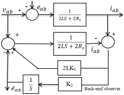
Figure 9. Block diagram of BEMF observer
The block diagram of BEMF observer is presented in Figure 9 [12].
3.4.2 The commutation function and speed estimation
Widely used is the sensorless control method, which senses the zero crossing point (ZCP) of the BEMF to decide when devices should switch between them. Nevertheless, this method cannot detect ZCP at low speeds [11, 13]. Block diagram of back-EMF observer illustrates how the sensorless control approach can function more effectively when using the line-to-line BEMF observer to create the sensitive commutation function. The following is a definition of the commutation functions (CF):
$\begin{gathered}C F\left(\theta_1\right)=e_{\frac{b c}{e_{c a}^{\wedge}}}^{{\wedge}}, C F\left(\theta_2\right)=e_{\frac{a b}{e_{b c}^{\wedge}}}^{{\wedge}}, C F\left(\theta_3\right)=e_{\frac{c a}{e_{a b}^{\wedge}}}^{{\wedge}}\end{gathered}$ (58)
The magnitude of a back-estimated EMF is described. The rotor position and speed may be found using basic mathematical calculations. The BEMF's size and speed in a brushless DC motor are directly correlated:
$E=K_e \omega_e$
where, $\omega_e$ is an electrical angular velocity, $E$ is a BEMF magnitude, and $K_e$ is a BEMF constant. The highest magnitude of the line-to-line BEMF provided by the unknown input observer is used to determine the BEMF's magnitude $[15,16]$. Consequently, the speed can be computed using the BEMF's estimated magnitude in the manner shown as below:
$\omega_e^{\wedge}=\frac{E^{\wedge}}{K_e} ; \omega_m^{\wedge}=\frac{2}{P} \omega_e^{\wedge}$
3.5 Speed controller of BLDC
The difference between a processed variable that is measured and goes through proportional, integral, and derivative computations and the intended set point is the error that a PID controller continuously measures [17-19]. To generate a control signal proportional to the input error signal e(t) as well as the input error signal e(t)'s integral and derivative.
$U(t) \propto\left[e(\mathrm{t})+\int e(t) d t+\frac{d}{d t} e(t)\right]$ (46)
where, Proportional (P) Term- $U(t) \propto e(t)$. Integral (I) Term- $U(\mathrm{t}) \propto \int e(t) d t$. Derivative (D) Term- $U(t) \propto \frac{d}{d t} e(t)$.
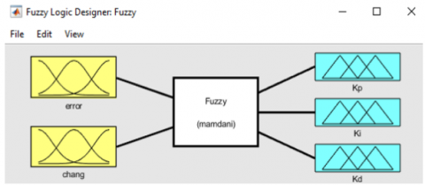
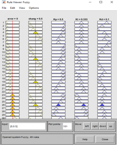
The fundamental building block for storing knowledge in fuzzy systems is a fuzzy rule. Fuzzy logic controller consists of Fuzzy rules, inference, the fuzzification and defuzzification [11, 20, 21]. Figures 10-12 show the FPID controller's fuzzy inference system, rule base view and surface view respectively.
Figure 10. Fuzzy inference block
Figure 11. Rule base view
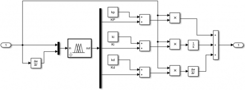
A control system that combines the principles of both fuzzy logic control and the traditional PID control algorithm. Instead of using fixed PID gains (Kp, Ki, Kd), the FPID controller dynamically adjusts these gains based on fuzzy logic rules and the system's operating conditions.
The Kp, Ki, and Kd surface viewers with error and change are displayed in Figures 12.
Figure 12. Viewers of Kp, Ki and Kd
The fuzzy inference block is presented in Figure 9, while Figure 10 presents the rule base view. The rule viewer for the fuzzy interface system is also shown in Figure 11.
4.1 Fuzzifier designer
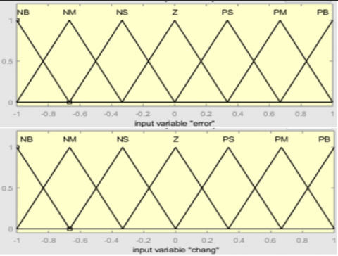
Figure 13 illustrates the BLDC motor speed error along with the variation in control signals as represented in the fuzzy membership functions. Each crisp input value is mapped to one of the seven fuzzy linguistic terms—NB, NM, NS, Z, PS, PM, and PB—by assigning an appropriate degree of membership. The corresponding ranges (universe of discourse) and membership values for these functions are summarized in Table 1.
Figure 13. Membership function of error and change in speed of motor
Table 1. Fuzzy rules change PID gain
|
Error |
Change |
||||||
|
NB |
NM |
NS |
Z |
PS |
PM |
PB |
|
|
NB |
PB/Z/PS |
PB/Z/NS |
PM/Z/NB |
PM/Z/Z |
PS/Z/PS |
Z/Z/Z |
Z/Z/PM |
|
NM |
PB/NB/PS |
PM/NS/NS |
PM/NM/NB |
PS/NS/NB |
PS/NS/NB |
Z/Z/NM |
Z/Z/PS |
|
NS |
PM/NB/Z |
PM/NS/NS |
PM/NS/NM |
PS/Z/NM |
Z/Z/NS |
NS/PS/Z |
NS/PS/Z |
|
Z |
PM/NM/Z |
PM/NS/NS |
PS/NS/NS |
Z/PS/NS |
NS/PS/NS |
NS/PM/Z |
NM/PM/Z |
|
PS |
PS/NM/Z |
PS/NS/Z |
Z/Z/Z |
NS/PS/Z |
NS/PS/Z |
NS/PM/Z |
NM/PB/Z |
|
PM |
PS/Z/PB |
Z/Z/PB |
NS/PS/PS |
NS/PS/PS |
NM/PS/Z |
NS/PS/Z |
NB/PB/Z |
|
PB |
Z/Z/PB |
Z/Z/PM |
Z/PS/PS |
Z/PM/Z |
Z/PM/Z |
NM/PM/Z |
Z/PB/PS |
4.2 Rule based construction
The following 49 fuzzy relations can be drawn using the aforementioned guidelines. Table 1 displays the rule tables for changes in proportionality, integral, and derivative.
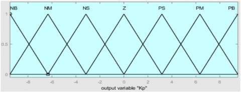
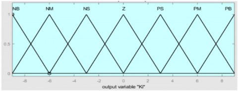
Using the centroid de-fuzzification technique, we were able to convert the inference process into the crisp values that the actual system employed. Figures 14-16 display the output defuzzification membership functions for change of proportional, integral and derivative gain.
Figure 14. Change of proportional gain output membership function
Figure 15. Change of integral gain output membership function
Figure 16. Change of derivative gain output membership function
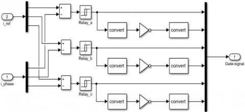
D) Hysteresis current controller
The reference current has a hysteresis band limit and the phase current is guaranteed to follow reference current's route between the fixed hysteresis bands [22] (Figure 17).
Figure 17. Hysteresis current controller
$i_{\text {ref }}=\left(\omega_{\text {ref }}-\omega_{\text {est }}\right) *$ controller output
where, $i_{\text {ref }}$ is reference current, $\omega_{\text {ref }}$ is reference speed, $\omega_{\text {est }}$ is estimated speed.
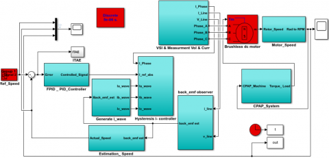
4.3 Modeling of BLDC using FPID controller
MATLAB Simulink is used to model the continuous positive airway pressure device with the brushless dc motor and its drive. Figure 18(a) shows the complete Simulink model of the three-phase BLDC motor with the CPAP device. Figure 18(b) depicts the fuzzy- PID controller Simulink model.
Figure 18. (a). Simulink model of BLDC motor with CPAP device control system, (b). Fuzzy- PID controller Simulink model
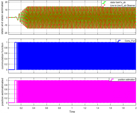
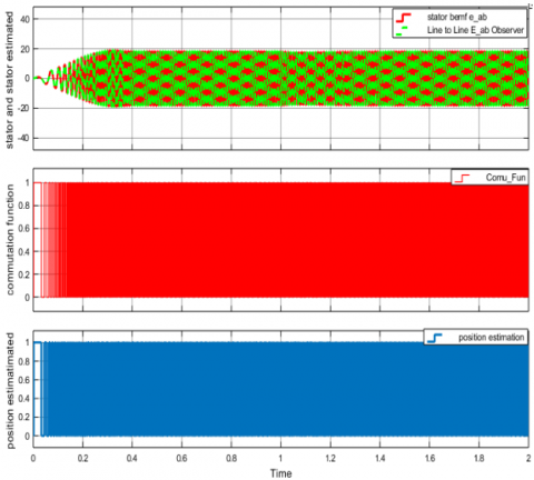
The performance of the FPID controller with a BEMF observer is examined in this section. Figure 19 shows the FPID controller's results, the stator BEMF (eab), and the estimated line-to-line BEMF (eab) using line-to-line current (iab) and voltage (vab). The predicted BEMF settles to zero in a relatively short time, and the performance is compared to the PID controller output, as shown in Figure 20. As a consequence of the findings, the suggested system's estimated rotor speed and BEMF observation outperform the PID controller in terms of performance and transient response time.
Figure 19. FPID controller-based on BEMF observer, estimation results
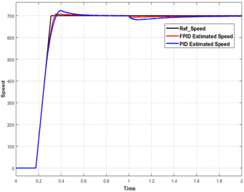
Figure 19 shows the comparison of the control speed of the FPID and PID controller. The FPID controller achieved a high performance than the PID controller with rotor speed varying at 0-700 rpm reference input and load torque of 0.7 Nm at 0.2 sec. The CPAP device load torque is between 0.2 — 0.7 Nm. The additional terms of the fuzzy logic with proportional, integral and derivative give the FPID controller a sophisticated technique that improves the system's robustness, flexibility, and dynamic performance.
Figure 20. PID controller-based on BEMF observer, estimation results
Figure 21 shows the stator BEMF and estimated BEMF. The estimated BEMF settles to zero at very little time and has a high performance than that of the PID controller output as shown in Figure 20.
Figure 21. FPID and PID controller based on BEMF observer estimated speed
Table 2. Performance comparison of the fuzzy-PID and PID controller
|
Performance Specification |
FPID Controller |
PID Controller |
|
Rise time |
0.1710 s |
0.2105 s |
|
Settling time |
1.0055 s |
1.3509 s |
|
Over shoot |
2.0721% |
3.2718% |
|
Steady state error |
2.4151% |
8.7676% |
The observed BEMF behavior indicates that the speed estimator is effective.
From Table 2, the proposed controller gives much high performance with respect to PID controller and FPID result of rise time, settling time, overshoot and steady state error is 0.171 sec, 1.0055 sec, 2.0721%, 2.4151%, respectively.
The fuzzy-PID controller exhibited faster settling times, reduced overshoot, and enhanced robustness to varying load conditions and disturbances, all of which are critical for ensuring consistent and comfortable airflow delivery in sleep apnea therapy.
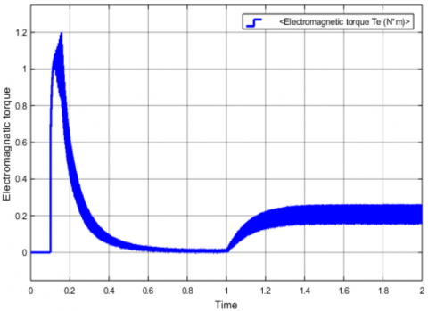
Torque response shown in Figure 22 faster recovery time, which took less than 0.2 s. An electromagnetic torque Te is the graphically parameters like rise time, settling time, overshoot time and steady state error expect result.
Figure 22. Load torque (Nm)
5.1 Simulation of CPAP machine characteristics
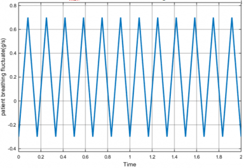
The patient's breathing load varies with the CPAP system, ranging from 0.7 g/s outflow during inhalation to -0.3 g/s inflow during expiration. As seen in Figure 23, a similar triangle wave is produced in place of the respiratory signal.
Figure 23. Air mass flow (g/s) of the patient breathing vs. time (s)
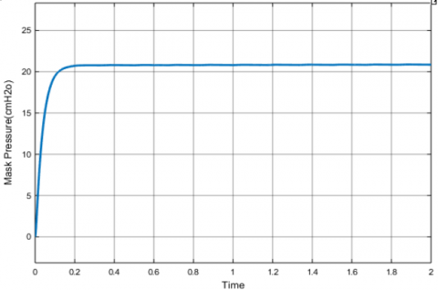
Figure 24. FPID controller-based mask pressure (cmH2O) vs. time(s)
Regardless of the patient's breathing burden, the mask pressure should stay constant. To maintain a consistent mask pressure, the mask vent air flow characteristics should be adjusted to the patient's varying breathing demand, as seen in Figure 24.
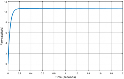
The mask receives mass inflows ranging from 0.1 to 21.5 cmH2O. As a result, mask pressure is discovered to be constant at 22 cmH2O, resulting in a continuous mask vent bias flow of 10.8 kp/s, as illustrated in Figure 25.
Figure 25. FPID controller-based flow rate (kp/sec) vs. time (sec)
In medical applications, a key limitation of BLDC motors is their fixed operating speed. Since the blower fan does not adjust to changes in the patient’s airway pressure during breathing, this results in discomfort for the patient’s respiratory system. By integrating a fuzzy logic controller with a PID controller, the operational gaps in the machine are filled and the ideal motor speed is controlled. As a consequence of altering the electric motor's rising time, settling time, and steady state error demonstrating the high performance of the CPAP application.
The results of the air mask pressure for patients using the motor speed controller of the FPID controller, the stator BEMF eab and the estimation line-to-line BEMF observed (eab) based line-to-line current (iab) and voltage (vab) achieved better simulation results. Figures 16-19 illustrate the performance of sensorless BLDC motor which is summarized in Table 2. Surprisingly, the sensorless BLDC motor is slightly more beneficially to the patient's than other electric motors with help of the expert FPID controller.
The FPID controller was found to be the most effective controller when compared to previous studies [2, 6, 10, 13]. The research study suggests that integration of controllers such as PI and PID controller has a beneficial effect.
The blower fan on the respirator pressurizes the air within the mask, while the patient is sleeping, which is why the sensor-less BLDC motors is crucial for CPAP. With FPID, we can optimize patients’ comfort, safety, and efficacy beyond what was possible with the conventional controllers. It is crucial that the physician has a thorough awareness of the system in place to deliver CPAP in their area. The MATLAB/Simulink simulation results show that Figures 20-22 achieve better results with the high performance of the CPAP machine due to steady state responses of the machine-like rise time, settling time, steady state error etc., are in the limit of control standard. Therefore, the proposed controller is better than the PID and FPID controllers compared to previous studies as illustrated in the results.
The limitation of this study is in that fact that the work was restricted to simulation using MATLAB and practical implementation was not achieved. This was due to the challenge to the cost implications of implementing the system, and the availability of components.
This study demonstrates the effectiveness of a brushless DC (BLDC) motor driven by a hysteresis control scheme combined with a fractional-order PID (FPID)-based sensorless speed estimation for use in a continuous positive airway pressure (CPAP) system. Accurate speed regulation allows the blower to dynamically track a patient’s breathing pattern, thereby maintaining the required airway pressure during sleep. The proposed FPID controller is modeled and simulated for speed regulation, where the rotor speed of the BLDC motor is estimated using a back electromotive force (BEMF) observer. Under a constant CPAP load condition, the controller exhibited reliable performance. In the system model developed in MATLAB/Simulink, the estimated rotor speed of the BLDC motor is converted into pressure and applied to the reservoir to mimic the CPAP operation. Simulation results indicate that with the FPID controller, the speed response improves significantly, reducing the rise time to 0.1710 seconds and the settling time to 1.0055 seconds. The findings of this study suggest that the fuzzy-PID control approach offers a promising solution for achieving precise and reliable speed regulation of BLDC motors in sleep apnea devices.
The findings of this study suggest that the fuzzy-PID control approach offers a promising solution for achieving precise and reliable speed regulation of BLDC motors in sleep apnea devices.
|
emi |
Back EMF in phase |
|
θr |
Electrical angle of rotor |
|
λmi |
Flux linkage in phase |
|
ρa |
Average air density |
|
ωe |
Electrical angular speed |
|
ωm |
Mechanical rotor speed |
|
µ |
Derivative order |
|
A |
Area of reservoir |
|
B |
Friction constant |
|
Cm |
Nasal mask capacitance |
|
Cr |
Reservoir capacitance |
|
D |
Reservoir internal diameter |
|
E |
Back EMF magnitude |
|
Ea |
Phase back EMF |
|
Eb |
Phase back EMF |
|
Ec |
Phase back EMF |
|
f(θr) |
Trapezoidal function |
|
Ke |
Back EMF constant |
|
Kf |
Electromagnetic force constant |
|
Ks |
Reservoir Shock factor into tube |
|
Kt |
Torque constant |
|
Lt |
Reservoir length |
|
P |
Air delivers unit pressure |
|
Pm |
Mask of pressure |
|
Pr |
Reservoir pressure |
|
Rb |
Bias mass airflow pressure drop gradient |
|
Rm |
Tube mass flow pressure drop gradient |
|
Rs |
Stator resistance |
|
RV |
Tube velocity pressure drop gradient |
|
Ta |
Absolute air temperature |
|
Te |
Electromagnetic torque |
|
TL |
Load torque |
|
Vt |
Transmission tube air velocity |
|
Yb |
Bias mass airflow Y coordinates |
|
Ym |
Tube mass flow pressure drop Y coordinate |
|
YV |
Tube velocity pressure drops Y coordinate |
[1] Zhao, J., Yu, Y. (2011). Brushless DC Motor Fundamentals Application Note. MPS.
[2] Saleh, A.L., Obed, A.A. (2014). Speed control of brushless DC motor based on fractional order PID controller. International Journal of Computer Applications, 95(4): 1-6. https://doi.org/10.5120/16579-6269
[3] Yedamale, P. (2003). Brushless DC (BLDC) motor fundamentals. Microchip Technology Inc, 20(1): 3-15.
[4] Duad, A. (2010). Brushless D.C. motor for medical applications. In EDEB'10: Proceedings of the 4th International Conference on Energy & Development, Environment & Biomedicine, Stevens PointWisconsinUnited States, pp. 27-33.
[5] Volsko, T.A. (2019). Devices used for CPAP delivery. Respiratory Care, 64(6): 723-734. https://doi.org/10.4187/respcare.06625
[6] Ma, Z. (2022). Design, manufacture, and evaluation of customised CPAP breathing device for the treatment of Obstructive Sleep Apnoea (OSA) syndrome. PhD Thesis, University School of Engineering, Newcastle University.
[7] Salau, A.O., Kanchana, K., Anoop, K.J., Markus, E.D., Braide, S.L. (2024). Suppression of over voltage in SiC-based inverter fed induction motor. Australian Journal of Electrical and Electronics Engineering, 21(1): 11-28. https://doi.org/10.1080/1448837X.2023.2250132
[8] Kumari, S., Laxminarayana, Y., Tarakalyani, S. (2013). Modeling and simulation of BLDC motor for aiding and opposing loads. IOSR Journal of Electrical and Electronics Engineering, 7(4): 59-67.
[9] Abouseda, A.I., Doruk, R., Emin, A., Akdeniz, O. (2025). Modeling, dynamic characterization, and performance analysis of a 2.2 kW BLDC motor under fixed load torque levels and variable speed inputs: An experimental study. Actuators, 14(8): 400. https://doi.org/10.3390/act14080400
[10] Meenu, M.M., Hariharan, S. (2015). Position sensorless control of BLDC motor in continuous positive airway pressure device. In 2015 International Conference on Control Communication & Computing India (ICCC), Trivandrum, India, pp. 230-235. https://doi.org/10.1109/ICCC.2015.7432897
[11] Kaloi, M.K., Ali, E., Mustafa, G., Nizamani, N., Memon, M.A., Khatri, A.R., Kaloi, G.S. (2020). Fuzzy-PID based control scheme for PMDC series motor speed control. Indian Journal of Science and Technology, 13(28): 2911-2923. https://doi.org/10.17485/IJST/v13i28.653
[12] Khubalkar, S.W., Chopade, A.S., Junghare, A.S., Aware, M.V. (2016). Design and tuning of fractional order PID controller for speed control of permanent magnet brushless DC motor. In 2016 IEEE First International Conference on Control, Measurement and Instrumentation (CMI), Kolkata, India, pp. 326-330. https://doi.org/10.1109/CMI.2016.7413764
[13] Li, Q., Huang, X., Li, J., Liu, G., Tao, J. (2020). Design of sensorless high speed BLDCM controller for molecular pump. Journal of Physics: Conference Series, 1654: 012039. https://doi.org/10.1088/1742-6596/1654/1/012039
[14] CPAP machine. https://www.google.com/search?q=cpap+machine&tbm=isch&ved=2ahUKEwi90MLZ1P35AhUXw4UKHc34AZMQ2cCegQIABAA&oq=cpap+machine.
[15] Mahmud, M., Motakabber, S.M.A., Alam, A.Z., Nordin, A.N., Habib, A.A. (2020). Modeling and performance analysis of an adaptive PID speed controller for the BLDC motor. International Journal of Advanced Computer Science and Applications, 11(7): 272-276.
[16] Mishra, A., Murthy, S.K., Raj, A.B. (2017). Mathematical modeling and simulation of driving unit of brushless DC motor. International Journal of Advance Research in Science and Engineering, 7(4): 644-652.
[17] Mahmud, M., Motakabber, S.M.A., Alam, A.Z., Nordin, A.N. (2020). Control BLDC motor speed using PID controller. International Journal of Advanced Computer Science and Applications, 11(3): 477-481.
[18] Sall, M., Kebe, A., Gueye, I., Diop, M. (2021). Comparative study between the PID regulator and the fuzzy regulator applied to the operation of a brushless DC motor. Energy and Power Engineering, 13(11): 365-376. https://doi.org/10.4236/epe.2021.1311025
[19] Maghfiroh, H., Nizam, M., Praptodiyono, S. (2020). PID optimal control to reduce energy consumption in DC-drive system. International Journal of Power Electronics and Drive System, 11(4): 2165-2172. https://doi.org/10.11591/ijpeds.v11.i4.pp2164-2172
[20] Maghfiroh, H., Ramelan, A., Adriyanto, F. (2022). Fuzzy-PID in BLDC motor speed control using MATLAB/Simulink. Journal of Robotics and Control, 3(1): 8-13. https://doi.org/10.18196/jrc.v3i1.10964
[21] Siong, T.C., Ismail, B., Siraj, S.F., Tajuddin, M.F.N., Jamoshid, N.S., Mohammed, M.F. (2010). Analysis of fuzzy logic controller for permanent magnet brushless DC motor drives. In 2010 IEEE Student Conference on Research and Development (SCOReD), Kuala Lumpur, Malaysia, pp. 436-441. https://doi.org/10.1109/SCORED.2010.5704049
[22] Çabuk, A.S. (2021). Sensorless control of outer rotor brushless DC motor with back-EMF observer for drone. Balkan Journal of Electrical and Computer Engineering, 9(4): 379-385. https://doi.org/10.17694/bajece.958760