M’hamed Sahnoun*![]() | Radhwane Sadouni
| Radhwane Sadouni![]() | Salim Djeriou
| Salim Djeriou![]()
© 2025 The authors. This article is published by IIETA and is licensed under the CC BY 4.0 license (http://creativecommons.org/licenses/by/4.0/).
OPEN ACCESS
The increasing demand for irrigation in rural areas has led to significant interest in photovoltaic water pumping systems (PVWPS), as grid connectivity in these regions is often unavailable or economically unfeasible. However, PVWPS face challenges related to system reliability and efficiency due to variations in environmental conditions. Building on recent advancements in the field and leveraging the notable benefits of six-phase induction motors, this study proposes a control strategy for PVWPS aimed at optimizing motor speed under variable irradiance conditions to enhance the overall performance of the water pumping system. The proposed control architecture consists of two main stages. In the first stage, maximum power is extracted from the photovoltaic generator (PVG) using a conventional Perturb and Observe (P&O) algorithm that controls a DC-DC boost converter. In the second stage, indirect rotor field-oriented control (IRFOC) is applied to a dual stator induction motor (DSIM) with a minimal sensor configuration. This approach eliminates the need for current sensors, thereby improving hardware reliability, reducing system complexity, and maintaining adaptability to solar power fluctuations. To achieve smooth and efficient operation, the motor speed is regulated using a novel speed optimizer based on an artificial neural network (ANN), which dynamically adjusts the speed reference in response to changes in solar irradiance. The system’s performance was evaluated through comprehensive simulations under various operating conditions.
indirect rotor field-oriented control, motor control, dual stator induction motor, photovoltaic pumping system, maximum power point tracking, speed optimizer, double stage photovoltaic system, artificial neural network
Lately, due to recent changes, the world faces a critical energy problem, which has increased attention toward using photovoltaic energy sources, especially in pumping systems. Diesel-powered pumping systems have many drawbacks, including fluctuating fuel costs, poor efficiency, low reliability, and high maintenance expenses [1]. Stand-alone photovoltaic water pumping systems (PVWPS) offer a practical solution in rural areas [2], where grid connectivity is often unavailable or difficult to achieve, and system autonomy is essential [3]. However, these systems still face issues related to variations in solar irradiance that directly affect the power generated by the photovoltaic panels. Such fluctuations cause operational instability and efficiency degradation.
To maximize system performance, the motor-pump must operate at an optimal speed that matches the available power [4]. Integrating motor control strategies into PVWPS has thus gained significant attention due to the growing need for efficient and sustainable solutions. Indirect rotor field-oriented control (IRFOC) has emerged as a reliable approach for controlling induction motors, offering superior dynamic performance and improved operational efficiency. Research has explored both single-stage and two-stage configurations for photovoltaic pumping systems. The two-stage configuration consists of two converter stages to optimize performance under varying irradiance [4], while the single-stage configuration employs just one DC-to-AC converter and utilizes a maximum power point tracking (MPPT) algorithm to generate the speed reference [5]. In the two-stage configuration, control strategies are used to determine the optimal speed reference; some studies have achieved this through curve fitting based on historical solar irradiance data, predefined mathematical models, or intelligent optimization algorithms [6]. Notably, DSIMs have gained popularity due to their high fault tolerance, lower torque ripple, and improved power distribution, compared to conventional three-phase induction motors, DSIMs offer several advantages in PVWPS applications. For example, DSIMs demonstrate an efficiency improvement of approximately 5–10% under variable irradiance conditions [7]. Additionally, due to their dual winding structure, they offer higher starting torque and improved reliability. Moreover, in scenarios where a three-phase induction motor experiences a fault, such as the loss of one or more phases, a common approach is to add a secondary three-phase induction motor as a backup. However, an alternative and more cost-effective solution is to employ a poly-phase induction motor like DSIM, which is naturally having high fault tolerance and can maintain operation under such faulty conditions, thereby significantly reducing overall system costs. These features make DSIMs particularly attractive for off-grid water pumping in rural and remote areas leading to enhanced system reliability [8].
Existing literature primarily focuses on evaluating system efficiency, dynamic responses to irradiance variations, and the robustness of various control strategies. Some studies emphasize energy savings through improved MPPT algorithms [9], while others assess torque characteristics and smooth operation under real-world conditions.
Saady et al. [10] eliminated most current sensors in a three-phase PV pumping drive to improve hardware simplicity, while Belaroussi et al. [11] optimized the DC-bus voltage for conventional induction motor pumps to increase efficiency. Singh et al. [12] presented a standalone PV pump with further sensor reduction, and Talbi et al. [13] designed a robust controller that tolerates sudden irradiance and load changes—yet all four studies retained standard three-phase or generic multi-phase machines. Research on dual-stator induction motors (DSIM) is far sparser. Adjati et al. [14] analyzed DSIM operation in a steady-state PV–PV-fuel-cell hybrid pump without focusing on dynamic speed regulation, Roubache and Chaouch [15] implemented sensorless backstepping control using an ANFIS-based Luenberger observer (ANFIS-LO) for a PV-powered DSIM in EV emulation, achieving superior speed estimation and robustness under varying irradiance and load transients and Jain et al. [16] employed a dual-inverter, open-end-winding configuration but concentrated mainly on the power stage rather than advanced, irradiance-adaptive control.
Consequently, the literature lacks a comprehensive strategy that combines maximum power point tracking, employs sensor-minimal indirect field-oriented control, and dynamically optimizes DSIM speed under fluctuating solar conditions. The present study addresses this gap by providing a comprehensive analysis and implementation of a sensorless IRFOC strategy for DSIMs, coupled with a real-time speed optimizer that responds to irradiance variability, thus advancing the performance of photovoltaic water pumping systems. In contrast to battery-based configurations that increase cost, complexity, and maintenance requirements, the proposed system adopts a direct coupling strategy without energy storage, enhancing reliability and system simplicity for rural and off-grid applications [17].
This study aims to fill the gap by presenting a comprehensive analysis of sensorless IRFOC for DSIMs, considering solar power perturbations and optimizing motor performance for improved efficiency and reliability. The proposed research introduces an innovative sensorless IRFOC strategy for a PVWPS using DSIM to drive a centrifugal pump, leveraging the advantages of reduced sensor dependency [6, 12] The system is powered by a photovoltaic generator (PVG) consisting of two chains of 11 series-connected panels directly feeding a boost converter controlled by a Perturb and Observe (P&O) algorithm to adjust the duty cycle (α) for maximum power extraction under varying irradiance. This power is then supplied to a conventional sinusoidal pulse width modulation (SPWM) voltage source inverter (VSI) enhanced with the proposed IRFOC that eliminates the need for current sensors while maintaining precise motor control to optimize performance and maximize efficiency [18]. The control strategy is further enhanced by a novel speed optimizer, implemented using an artificial neural network (ANN), which dynamically adjusts the reference speed of the motor based on variations in PVG power, ensuring optimal system operation at different levels of irradiance.
To evaluate the proposed system, a detailed simulation model was developed using MATLAB/Simulink. Simulation results demonstrate that, compared to conventional control schemes, the proposed method achieves a 37.5% reduction in starting torque peak, reduces steady-state torque ripple from ±0.26 Nm to ±0.17 Nm, and improves speed tracking error from 11% down to less than 1%. Furthermore, water flow rate is increased by 7.5%, and power conversion efficiency is enhanced from 81% to over 94% under dynamic irradiance scenarios.
The remainder of this paper is organized as follows: Section 2 outlines the design of the photovoltaic water pumping system; Section 3 details the proposed control strategy; Section 4 discusses the simulation results; and Section 5 presents the conclusions.
The proposed PVWPS configuration is shown in Figure 1. Consisting of the PVG fed the DSIM using a boost converter with an MPPT algorithm to adjust the duty cycle for achieving the maximum power in variable irradiance, while the IRFOC is proposed to control the speed and torque of this DSIM by two VSI with a speed reference based on a speed optimizer [1].
Figure 1. System configuration of the proposed PVWPS
2.1 Modelling of the photovoltaic generator
Figure 2 illustrates the schematic of the single diode equivalent circuit of a photovoltaic cell. This model contains the four fundamental parts, current source $I_{p h}$, diode $d$, shunt resistor $R_{s h}$, series resistor $R_{s h}$. The current generated by this PV panel represented by Eq. (1) as follows [19]:
$\begin{gathered}I_{p v}=I_{p h}-I_d-I_{s h} =I_{p h}-I\left(e^{\left(\frac{q\left(V_{p v}+R_s I\right)}{K A T}\right)}-1\right)-\frac{V_{p v}+R_s I_{p v}}{R_{s h}}\end{gathered}$ (1)
Figure 2. PV module equivalent circuit [19]
2.2 Boost converter design
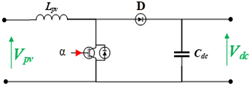
The corresponding DC-DC boost converter topology is shown in Figure 3, which is placed at a point between the PVG and the voltage source inverter, for voltage amplification and power optimization.
Figure 3. Boost converter topology
Eqs. (2) and (3) describe the output voltage and current based on the voltage and current input.
$V_{d c}=\frac{V_{p v}}{1-a}$ (2)
$I_{d c}=I_{p v}(1-a)$ (3)
2.3 Voltage source inverter
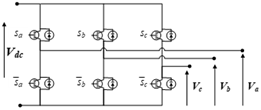
The voltage source inverter VSI is an essential component for supplying AC loads in photovoltaic systems. In the proposed system double three-phase inverters are used to feed the six-phase induction motor. Figure 4 illustrates the three-phase VSI configuration. Eq. (4) expresses the induction motor stator voltage as a function of upper switch states, highlighting the relationship between the inverter operation and motor performance.
$\left[\begin{array}{l}V s_a \\ V s_b \\ V s_c\end{array}\right]=\frac{V_{p v}}{3}\left[\begin{array}{ccc}2 & -1 & -1 \\ -1 & 2 & -1 \\ -1 & -1 & 2\end{array}\right]\left[\begin{array}{l}s_a \\ s_b \\ s_c\end{array}\right]$ (4)
Figure 4. Equivalent Circuit of the VSI
2.4 Modelling of the DSIM
To simplify the modelling of the DSIM, Park transformation is used to reduce the number of differential equations, the mathematical model of the motor can be represented as [19]:
•Dual stator voltage:
$\left\{\begin{array}{l}V_{d s 1}=R_{s 1}+\frac{d \Phi_{d s 1}}{d t}-\omega_s \Phi_{q s 1} \\ V_{q s 1}=R_{s 1}+\frac{d \Phi_{q s 1}}{d t}+\omega_s \Phi_{d s 1} \\ V_{d s 2}=R_{s 2}+\frac{d \Phi_{d s 2}}{d t}-\omega_s \Phi_{q s 2} \\ V_{q s 2}=R_{s 2}+\frac{d \Phi_{q s 2}}{d t}+\omega_s \Phi_{d s 2}\end{array}\right.$ (5)
•Rotor voltage:
$\left\{\begin{array}{l}0=R_r I_{d r}+\frac{d \Phi_{d r}}{d t}-\omega_{s r} \Phi_{q r} \\ 0=R_r I_{q r}+\frac{d \Phi_{q r}}{d t}+\omega_{s r} \Phi_{d r}\end{array}\right.$ (6)
•Flux equations:
$\left\{\begin{array}{c}\Phi_{d s 1}=L_{s 1} I_{d s 1}+L_m\left(I_{d s 1}+I_{d s 2}+I_{d r}\right) \\ \Phi_{q s 1}=L_{s 1} I_{q s 1}+L_m\left(I_{q s 1}+I_{q s 2}+I_{q r}\right) \\ \Phi_{d s 2}=L_{s 2} I_{d s 2}+L_m\left(I_{d s 1}+I_{d s 2}+I_{d r}\right) \\ \Phi_{q s 2}=L_{s 2} I_{q s 2}+L_m\left(I_{q s 1}+I_{q s 2}+I_{q r}\right) \\ \Phi_{d r}=L_r I_{d r}+L_m\left(I_{d s 1}+I_{d s 2}+I_{d r}\right) \\ \Phi_{q r}=L_r I_{q r}+L_m\left(I_{q s 1}+I_{q s 2}+I_{q r}\right)\end{array}\right.$ (7)
where, $I_{d s 1}, I_{q s 1}, I_{d s 2}, I_{q s 2}, I_{d r}, I_{q r}$. The two stators and rotor current, respectively, in $(d-q)$ farm and $R_{s 1}, R_{s 2}, R_r$ representing the stator and rotor resistance with $L_m, L_{s 1}, L_{s 2}$, $L_r$ Mutual, stator, and rotor inductance.
The electromagnetic torque expression:
$\begin{gathered}T_{e m}=p \frac{L_m}{L_r+L_m}\left[\Phi_{d r}\left(I_{q s 1}+I_{q s 2}\right)\right. \left.-\Phi_{q r}\left(I_{d s 1}+I_{d s 2}\right)\right]\end{gathered}$ (8)
2.5 Centrifugal pump
The proposed system employs a centrifugal pump driven by a dual-stator induction motor (DSIM). The mechanical characteristics of the pump can be described through its load torque. $T_{\text {pump}}$, which follows a quadratic relationship with the motor speed:
$T_{pump}=A_p \Omega_m^2$ (9)
where, $A_p$ Represents the pump constant, determined by:
$A_p=P_n / \Omega_m^3$ (10)
with $P_n$ being the nominal power of the pump and $\Omega_m$, the motor angular velocity. This relationship characterizes the pump's behavior under various operating conditions [14].
Due to the high cost of the photovoltaic systems and the variation in the generated power from the PVG, it is necessary to utilize the system at the achievable maximum power point to ensure the highest efficiency of the system [9].
3.1 MPPT control algorithm
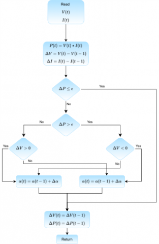
To maximize the conversion efficiency of the photovoltaic water-pumping system (PVWPS), it is necessary to track the instantaneous maximum power point of the array under continuously changing irradiance. In this work, the tracking task is entrusted to the Perturb and Observe (P&O) algorithm, whose operating sequence is summarized in the organigram shown in Figure 5.
Figure 5. Flow chart perturbs and observes MPPT algorithm
At the beginning of every control interval, the tracker samples the PV voltage and current, derives the corresponding power, and compares it with the value obtained one interval earlier.
The resulting power increment ($\Delta P$) is first tested against a small tolerance band $\varepsilon$. If $|\Delta P|$ is inside this dead-band, the duty-cycle command $\alpha$ is left unchanged, thereby preventing unnecessary oscillations around the optimum operating point. When $|\Delta P|$ exceeds $\varepsilon$, the algorithm examines the signs of both $\Delta P$ and the associated voltage increment $(\Delta V)$. A positive $\Delta P$ means that the last perturbation moved the operating point toward the maximum power point. consequently, the same perturbation direction is preserved. Conversely, a negative $\Delta P$. indicates divergence from the optimum, so the perturbation direction is reversed.
The duty cycle is then increased or decreased by a fixed step ∆α, and the new reference is applied to the DC-DC converter that feeds the motor-pump set. By iteratively repeating the four steps shown in Figure 5, measurement, comparison, decision, and update—the controller converges to the vicinity of the true maximum power point with a steady-state ripple that is bounded by the chosen tolerance $\varepsilon$ [19].
3.2 Speed optimizer
3.2.1 Conventional speed optimizer (CSO)
A common approach to setting the rotational speed of a photovoltaic water-pumping system (PVWPS) is to approximate the mechanical demand of the centrifugal pump using the steady-state cubic law [20]:
$P_m \approx T L \Omega_m=A p \Omega_m^3$ (11)
and, assuming lossless conversion, to derive an “optimal” speed from the PVG optimal power as Eq. (12):
$\Omega_m=\sqrt[3]{\frac{P_{o p t}}{A_p}}$ (12)
While this curve-fitted relation requires only a single parameter $A p$ and has minimal computational cost, it has notable limitations. It ignores losses such as motor and converter inefficiencies, causing systematic bias from the true optimum speed. Additionally, it is purely static and cannot capture dynamic effects like start-up transients or sudden irradiance changes. Moreover, it overlooks factors such as temperature, pipe friction, and component ageing that affect performance. Thus, although suitable for simple or preliminary studies, high-efficiency PVWPS designs benefit from model-based controllers that consider the full system dynamics.
3.2.2 Speed optimizer based on ANN
The artificial neural network speed optimizer was trained entirely on numerically generated data. A detailed MATLAB/Simulink model of the complete photovoltaic water-pumping system - PV array, boost converter, double three-phase inverter, induction- motor drive with indirect rotor field-oriented control (IRFOC), and centrifugal pumpstochastic irradiance values $G \in[0,1000] \mathrm{w} / \mathrm{m}^2$ were then drawn from a uniform distribution; 120 points were selected to guarantee a homogeneous coverage of the operating range. including the overall irradiance levels. For each irradiance sample, the simulator executed a steady-state sweep on the motor speed reference: the speed was gradually varied while the electrical MPP of the array was enforced, and the overall electro-hydraulic efficiency $\eta_{t o t}=\frac{P_{h y d r}}{P_{P V}}$ was monitored. The speed yielding the highest $\eta_{\text {tot }}$ under stable operating conditions (no stall, no over-current, lower speed error $e_{\Omega}=\frac{\Omega_m}{\Omega^*}$) was retained as the optimal target $\Omega *$ for that irradiance level.
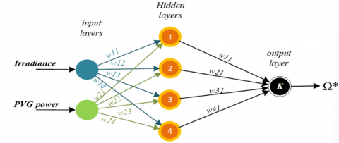
The final data set therefore consists of 120 triplets $\left[G, P_{P V}, \Omega^*\right]$ that directly link the available photovoltaic power to the best motor-pump speed. No pre-processing, filtering, or outlier removal was necessary because the deterministic simulation model generated the points; the raw values were fed to the ANN, which uses two inputs $\left(G, P_{P V}\right)$, one hidden layer with four hyperbolic tangent neurons, and a linear output neuron providing the reference speed (see Figure 6).
3.3 IRFOC for DSIM
The aim of Indirect Rotor Field Oriented Control (IRFOC) is to simulate the induction motor operation with a separated excitation DC motor by decoupling the torque and the flux control, with the rotor flux provided by the vector flow generated with the d-axis component. In contrast, the q-axis current generates the torque [21]. The conventional method is used in the paper [19]. This method uses feedback of the quadratic and direct current for the PI controllers to estimate the motor voltage [12]. Due to the complexity and their dependence on the number of regulators, we are implementing a simpler method that depends only on a mathematical model of the control technique, without the need for additional regulators or speed feedback demonstrated it in Figure 7 [22-25].
Figure 6. ANN speed optimizer structure
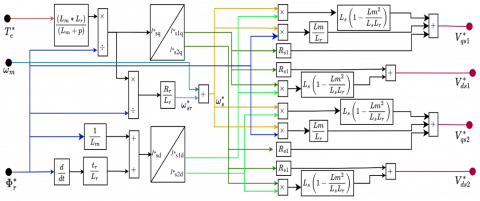
Figure 7. Block diagram of the implemented IRFOC method
The proposed photovoltaic water pumping system is powered by a dual stator induction motor (DSIM) controlled using a current-sensorless indirect rotor field-oriented control (IRFOC) strategy. Instead of relying on physical current sensors, this control scheme utilizes a mathematical model to estimate key motor variables such as flux and electromagnetic torque. This implementation reduces sensor dependency, enhances system robustness, and improves overall efficiency.
To further enhance dynamic performance, an artificial neural network (ANN)-based speed optimizer is implemented to continuously refine the motor speed reference. This ensures that the motor operates at the optimal point for extracting the maximum available power from the photovoltaic generator (PVG), particularly under varying irradiance conditions. The effectiveness of the ANN-based optimizer is evaluated by comparison with a conventional speed optimizer.
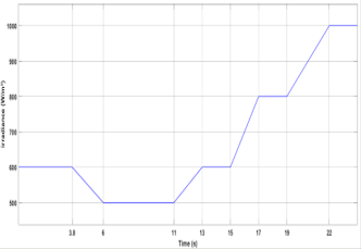
Figure 8. Irradiance variation
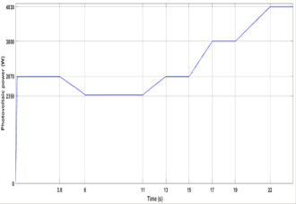
Figure 9. Output PV power
The conventional optimizer shows clear limitations, including high torque ripple during startup, significant speed deviation from reference, and reduced system efficiency. In contrast, the ANN-based approach provides smoother torque behavior, improved speed tracking, and better adaptability to irradiance fluctuations.
Simulation results were conducted under irradiance levels ranging from $600 \mathrm{w} / \mathrm{m}^2$ to $1000 \mathrm{w} / \mathrm{m}^2$. As shown in Figure 8, these variations caused PVG power output fluctuate between 2350 w and 4500 w . Despite the dynamic conditions, the Perturb and Observe (P\&O) MPPT algorithm successfully tracks the maximum power point, as illustrated in Figure 9.
4.1 Speed response and current response
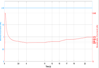
Figure 10. Direct and quadratic current
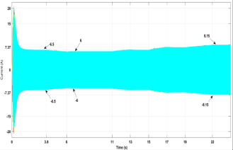
Figure 10 shows the ‘iqs’ changing with torque variations, while ‘ids’ follows the flux dynamics. This demonstrates good decoupling between torque and rotor flux. Furthermore, during the transient operation, the motor experiences a starting stator current $\left(I_{s 1, s t a r t} \approx 20 A\right)$ remains within safe limits using the proposed method, ensuring the motor operates within safe thermal boundaries, settling to steady state operation within $(8 A)$ range (Figure 11), limiting resistive losses and helping maintain higher efficiency.
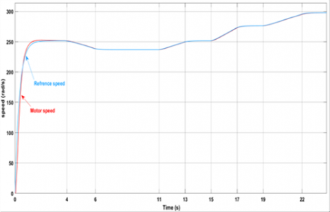
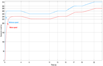
Figures 12 and 13 present the motor speed response under the ANN-based speed optimizer and conventional speed optimizer (CSO), respectively. The comparison exposes a significant performance difference that directly impacts the pumping system’s efficiency.
Figure 11. Stator current
Figure 12. Rotor and reference speed
Figure 13. Rotor and reference speed (CSO)
During the start-up phase $(0-1 \cdot s)$, the ANN-based optimizer demonstrates superior dynamic performance, reaching the steady-state speed of $250 \mathrm{rad} / \mathrm{s}$ in approximately $1.5 \cdot s$ with minimal overshoot of less than $2 \%$. In contrast, the conventional optimizer presents slow response characteristics, requiring nearly $2 s$ to approach the reference speed without reaching the reference with an error of $11 \%$. This faster settling time with the ANN optimizer translates to quicker pump priming and reduced start-up energy losses.
An important difference between the two optimizers is how they set their reference generation strategy. The CSO generates consistently higher speed references (reaching approximately $266 \mathrm{rad} / \mathrm{s}$ ) compared to the ANN optimizer (maintaining around $250 \mathrm{rad} / \mathrm{s}$ ). The CSO fails to consider the actual power available from the solar panels. As a result, the motor cannot reach these high-speed targets because there is not enough power, resulting in a persistent speed gap ranging from 27 to $35 \mathrm{rad} / \mathrm{s}$ throughout the operation period. This represents a $8-11 \%$ tracking error, with the actual motor speed level around $250 \mathrm{rad} / \mathrm{s}$ despite the higher reference commands. In contrast, the ANN-based optimizer intelligently adapts its reference generation to match the realizable speed given the availability of instantaneous PV . power, maintaining tracking errors below $2 \mathrm{rad} / \mathrm{s}(<\cdot 1 \%)$ and rendering the reference and actual speed curves virtually identical.
The ANN-based speed optimizer demonstrates superior dynamic performance in adapting to irradiance variations, further validating its effectiveness over the conventional approach. Between $t=2 \mathrm{~s}$ and $t=24 \mathrm{~s}$, as solar conditions change, the ANN system generates achievable speed references that the motor tracks almost instantaneously with smooth transitions. The CSO system, however, continues to demand unrealistic speeds while the motor responds slowly, and the tracking error grows larger when PV power is limited. This mismatch between reference generation and system capability not only compromises pumping efficiency but also creates conditions for the excessive torque demands that will be examined in the subsequent analysis.
4.2 Torque response and ripple analysis
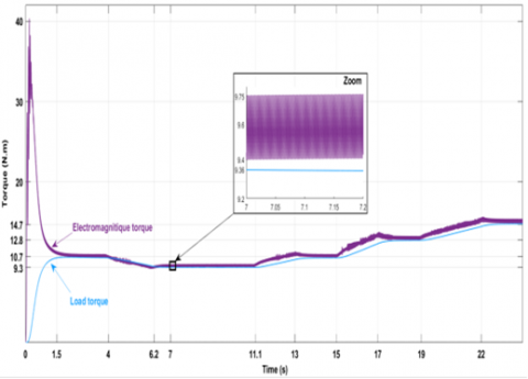
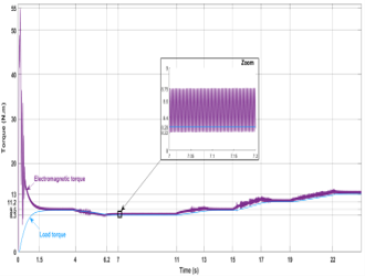
Figure 14 illustrates the electromagnetic and load torque profiles with the ANN speed optimizer, which confirms the system's ability to quickly adapt to variations in load induced by irradiance. The rise time was identical for both approaches ( $0.05 \mathrm{~s}$). The startup torque overshoot at approximately 40 Nm during and rapidly stabilizes to meet the load demand with minimal ripple. In Figure 15, the conventional speed optimizer shows a significantly higher startup torque overshoot of 55 Nm , representing an increase of $37.5 \%$ compared to the ANN-based approach, this excessive torque spike introduces greater mechanical stress and contributes to higher energy losses during transients. Both controllers settled to within $\pm 2 \%$ by each event time (i.e., by $1.5,13.2,17.4$, and $22.4 \mathrm{~s}$) with a recovery time lower then $0.3 \mathrm{~s}$. Thus, both strategies are equally fast in rise and settling, with increasing in the amplitude of the torque in the ANN-based system. Zoomed-in views of steady-state torque behavor reveal further distinctions. both strategies are equally fast in rise and settling, The ANN-based system (Figure 14, zoom) maintains a low ripple amplitude of approximately $\pm 0.17 \mathrm{Nm}$. Meanwhile, the conventional optimizer shows pronounced oscillations, reaching $\sim \pm 0.26 \mathrm{Nm}$. Furthermore, the conventional strategy demonstrates poor torque tracking with a steady state error of $0.24 \, \&\, 0.22 \, \mathrm{Nm}$ respectively, and a visible deviation between the electromagnetic torque and the load torque throughout the operating period.
Lower steady-state torque and higher ripple degrade dynamic performance and lead to mechanical vibrations and accelerated wear of pump components.
The combination of speed tracking error and torque ripple in the conventional system results in suboptimal torque matching and reduced efficiency.
Figure 14. Electromagnetic and load torque
Figure 15. Electromagnetic and load torque (CSO)
4.3 Water flow evolution analysis
Figures 16 and 17 illustrate the evolution of the water flow rate for the ANN-based optimizer and the conventional speed optimizer (CSO), respectively. The speed tracking profiles analyzed previously directly reflect the flow rate performance, as the centrifugal pump flow is proportional to the rotation speed ($Q \propto \Omega$).
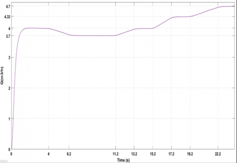
Figure 16. Water flow evolution
Figure 17. Water flow evolution (CSO)
During start-up $(0-2 s)$, the ANN-controlled system achieves a faster flow establishment, reaching a steady state flow of approximately $4 \mathrm{~m}^3 / \mathrm{h}$ in 1.5 seconds. The CSO system exhibits a slower response with almost 2 seconds to stabilize at a flow rate of approximately $3.7 \mathrm{~m}^3 / \mathrm{h}$. This $7.5 \%$ reduction in steady-state flow is directly the result of the persistent speed tracking error observed in Figure 13.
Variations in flow rate during changes in irradiance $(t= 2-24 s$ ) further demonstrate the performance gap. The ANN system maintains smooth flow transitions, varying from $3.5 \mathrm{~m}^3 / h$ to $4.38 \mathrm{~m}^3 / h$ as irradiance Changes. Meanwhile, the CSO system shows erratic flow behavior with pronounced dips, struggling to maintain the real hydraulic output.
4.4 Efficiency discussion
To ensure simplicity, cost-effectiveness, and long-term reliability, the proposed system is designed without any intermediate energy storage. The motor pump set is rated at 4.5 kW, indicating a close match with the peak power output of the photovoltaic generator. This sizing strategy enables direct coupling of the PV array to the motor to maximize energy utilization during daylight hours. Any power mismatch due to fluctuating irradiance is handled in real-time by the speed optimizer, ensuring dynamic alignment between the available solar power and the motor load demand.
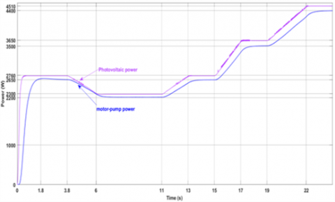
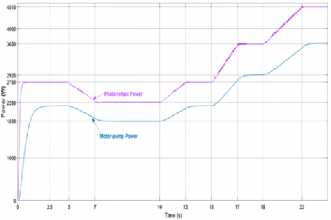
The efficiency comparison between Figures 18 and 19 reveals significant performance differences between the conventional and ANN-based optimizers. Both figures display photovoltaic input power (upper curves) and motor-pump absorbed power (lower curves) over a 24 seconds operational period.
Figure 18. Photovoltaic and absorbed power
During steady-state operation ($5-24$ seconds), the conventional optimizer (Figure 18) maintains a substantial gap between PV power ($\approx 3600 \mathrm{w}$) and motor power ($\approx 3000 \mathrm{w}$), indicating approximately 600 w of losses and yielding an efficiency around $81 \%$. In contrast, the ANN optimizer (Figure 19) demonstrates superior power tracking, with the motor power curve closely following the PV input power. The reduced gap between these curves indicates lower system losses and improved power transfer efficiency, approaching $94-96 \%$ during steady state.
The initial transient period (0-5 seconds) also shows marked differences. The ANN optimizer achieves faster power tracking convergence, reaching steady-state efficiency within 1.8-2 seconds compared to 2.5-3 seconds for the conventional system.
This rapid response translates to better energy utilization during startup phases, particularly important in variable irradiance conditions typical of PV systems. The overall improvement in power conversion efficiency directly correlates with the increased water delivery observed in the system performance.
Figure 19. Photovoltaic and absorbed power (CSO)
Stand-alone solar pumping systems are more suitable for remote and off-grid applications compared to other systems. To achieve optimal performance in such systems, this work employs a dual stator induction motor (DSIM) to drive a centrifugal pump, because PV system affected directly to environmental perturbation and that lead to fluctuation in the generated power a robust control strategy is required, the proposed one consist on the P&O MPPT algorithm alongside a novel configuration of current sensorless Indirect Rotor Field Oriented Control (IRFOC). Whereas conventional IRFOC relies on current feedback and PI controllers for accurate steady-state performance and efficient speed regulation, it can suffer from significant torque ripple under dynamic operating conditions. This leads to increased motor heating, reduced lifespan, and higher chances of system failure.
The proposed sensorless approach replaces current feedback and regulation with estimation based on mathematical modeling, which reduces control complexity and makes the system less sensitive to current variations. Simulation results demonstrate that this method lowers torque ripple with smoother motor operation and improves overall system reliability. the ANN optimizer yielded smoother steady operation: steady-state torque ripple (half-peak) decreased from $\pm 0.26 \mathrm{Nm}$ (conventional optimizer) to $\pm 0.17 \mathrm{Nm}$ (ANN), a $34.6 \%$ reduction.
Furthermore, the integration of an artificial neural network (ANN) speed optimizer generates optimal speed references based on real-time irradiance and PV power data. This ensures
that the DSIM operates at its most efficient point, ensures maximum power transfer from the PV array to the pump, thereby boosting system efficiency and performance.
As the next step, future work will focus on experimentally validating the proposed configuration, aiming to confirm the simulation results and demonstrate real-world feasibility and performance under varying environmental conditions.
|
PVWPS |
photovoltaic water pumping system |
|
PVG |
photovoltaic generator |
|
IRFOC |
Indirect rotor field-oriented control |
|
DSIM |
dual stator induction motor |
|
SPWM |
sinusoidal pulse width modulation |
|
VSI |
voltage source inverter |
|
MPPT |
maximum power point tracking |
|
P&O |
perturb and observe |
|
CSO |
conventional speed optimizer |
[1] Errouha, M., Motahhir, S., Combe, Q., Derouich, A. (2021). Intelligent control of induction motor for photovoltaic water pumping system. SN Applied Sciences, 3(9): 777. https://doi.org/10.1007/s42452-021-04757-4
[2] Sahuquet, A., Meunier, S., Cherni, J.A., Darga, A., Darga, S., Heinrich, M. (2024). Analysis of monitoring strategies for photovoltaic water pumping systems in low-income remote areas. In 2024 IEEE International Humanitarian Technologies Conference (IHTC), Bari, Italy, pp. 1-7. https://doi.org/10.1109/IHTC61819.2024.10855120
[3] Muralidhar, K., Rajasekar, N. (2021). A review of various components of solar water-pumping system: Configuration, characteristics, and performance. International Transactions on Electrical Energy Systems, 31(9): E13002. https://doi.org/10.1002/2050-7038.13002
[4] Errouha, M., Derouich, A., El Ouanjli, N., Motahhir, S. (2020). High‐performance standalone photovoltaic water pumping system using induction motor. International Journal of Photoenergy, 2020(1): 3872529. https://doi.org/10.1155/2020/3872529
[5] Rachaputi, B.P., Rathinadurai Louis, J., Sridharan, M. (2023). Novel sliding mode control of single-stage induction motor drive for solar water pumping applications. Electrical Engineering, 105(5): 3019-3032. https://doi.org/10.1007/s00202-023-01851-1
[6] Koneti, V., Mahesh, K., Anil Kumar, T. (2022). Improved performance of photovoltaic array for water pumping by fuzzy control in sensorless vector control of induction motor drive. International Journal of Ambient Energy, 43(1): 6598-6607. https://doi.org/10.1080/01430750.2021.1916589
[7] Terzic, M.V., Brkovic, B. (2018). Comparison between six-phase and three-phase high-speed drag-cup induction motor in terms of cup losses. In 2018 5th International Symposium on Environment-Friendly Energies and Applications (EFEA), Rome, Italy, pp. 1-6. https://doi.org/10.1109/EFEA.2018.8617077
[8] Koussaila, I., Lyes, K., Himour, K., Abdelhakim, D., Azeddine, H., Kaci, G., Fouad, B.M. (2020). Impact of polyphase induction motor on photovoltaic water pumping system. Journal Européen des Systèmes Automatisés, 53(6): 763-770. https://doi.org/10.18280/jesa.530602
[9] Saady, I., Karim, M., Bossoufi, B., El Ouanjli, N., Motahhir, S., Majout, B. (2023). Optimization and control of photovoltaic water pumping system using kalman filter based MPPT and multilevel inverter fed DTC-IM. Results in Engineering, 17: 100829. https://doi.org/10.1016/j.rineng.2022.100829
[10] Saady, I., Karim, M., Bossoufi, B., Motahhir, S., Adouairi, M.S., Majout, B., Lamnadi, M., Masud, M. and Al-Amri, J.F. (2021). Optimization for a photovoltaic pumping system using indirect field oriented control of induction motor. Electronics, 10(24): 3076. https://doi.org/10.3390/electronics10243076
[11] Belaroussi, O., Terki, A., Dahnoun, I., Lechelah, A. (2024). Optimal DC voltage control of a photovoltaic water pumping system for induction motor applications. Journal Européen des Systèmes Automatisés, 57(1): 155. https://doi.org/10.18280/jesa.570116
[12] Singh, B., Sharma, U., Kumar, S. (2018). Standalone photovoltaic water pumping system using induction motor drive with reduced sensors. IEEE Transactions on Industry Applications, 54(4): 3645-3655. https://doi.org/10.1109/TIA.2018.2825285
[13] Talbi, B., Krim, F., Rekioua, T., Mekhilef, S., Laib, A., Belaout, A. (2018). A high-performance control scheme for photovoltaic pumping system under sudden irradiance and load changes. Solar Energy, 159: 353-368. https://doi.org/10.1016/j.solener.2017.11.009
[14] Adjati, A., Rekioua, T., Rekioua, D., Tounzi, A. (2020). Study of dual stator induction motor in photovoltaic-fuel cell hybrid pumping Application. Journal Européen des Systèmes Automatisés, 53(5): 601-608. https://doi.org/10.18280/JESA.530502
[15] Roubache, T., Chaouch, S. (2024). Sensorless ANFIS-based control of PV-powered double stator induction motors for EVs. Journal Europeen des Systemes Automatises, 57(1): 67. https://doi.org/10.18280/jesa.570107
[16] Jain, S., Thopukara, A.K., Karampuri, R., Somasekhar, V.T. (2014). A single-stage photovoltaic system for a dual-inverter-fed open-end winding induction motor drive for pumping applications. Transactions on Power Electronics, 30(9): 4809-4818. https://doi.org/10.1109/TPEL.2014.2365516
[17] Rai, A., Dongol, K., Dhungana, S., Tamrakar, I. (2023). PV-based water pumping system without storage battery. KEC Journal of Science and Engineering, 7(1): 70-73. https://doi.org/10.3126/kjse.v7i1.60540
[18] Montanari, M., Peresada, S., Tilli, A. (2003). Sensorless indirect field oriented control of induction motor via adaptive speed observer. In Proceedings of the 2003 American Control Conference, Denver, CO, USA, pp. 4675-4680. https://doi.org/10.1109/ACC.2003.1242461
[19] Djeriou, S., Kheldoun, A., Sadouni, R. (2015). Fuzzy indirect field oriented control of a dual star induction motor water pumping system fed by photovoltaic generator. Engineering Intelligent Systems, 23(2): 63-76.
[20] Saady, I., Majout, B., Bossoufi, B., Karim, M., Elkafazi, I., Merzouk, S., Almalki, M.M., Alghamdi, T.A.H., Skruch, P., Zhilenkov A., Mobayen, S. (2025). Improving photovoltaic water pumping system performance with PSO-based MPPT and PSO-based direct torque control using real-time simulation. Scientific Reports, 15(1): 16127. https://doi.org/10.1038/s41598-025-00297-8
[21] Tikkani, A., Karasani, R.R., Venkata Govardhan Rao, K., Kalyan, C.N.S., Goud, B.S., Bajaj, M., Tuka, M.B. (2025). Fuzzy-2 deployment in indirect vector control and hybrid space vector modulation for a two-level inverter fed induction motor drive. Scientific Reports, 15(1): 13379. https://doi.org/10.1038/s41598-025-96600-8
[22] Sadouni, R., Meroufel, A. (2012). Indirect rotor field-oriented control (IRFOC) of a dual star induction machine (DSIM) using a fuzzy controller. Acta Polytechnica Hungarica, 9(4): 177-192.
[23] Slimene, M.B., Khlifi, M.A., Fredj, M.B. (2017). Sensorless speed control for dual stator induction motor drive using IFOC strategy with magnetic saturation. ACES Journal, 32(3): 262-267.
[24] Kari, M.Z., Mechernene, A., Meliani, S.M., Guenoune, I. (2018). Super-twisting strategy based indirect field oriented control without using the currents sensor: Application to IM. In 2018 International Conference on Electrical Sciences and Technologies in Maghreb (CISTEM), Algiers, Algeria, pp. 1-6. https://doi.org/10.1109/CISTEM.2018.8613540
[25] Adhya, S., Saha, D., Das, A., Jana, J., Saha, H. (2016). A comparative study between different modulation techniques used in field oriented control induction motor drive. In 2016 2nd International Conference on Control, Instrumentation, Energy & Communication (CIEC), Kolkata, India, pp. 141-145. https://doi.org/10.1109/CIEC.2016.7513777