Manal Abdulsattar Muhammed![]() | Nuralhuda Aladdin Jasim*
| Nuralhuda Aladdin Jasim*![]() | Zainab Jaber Mohammed
| Zainab Jaber Mohammed![]() | Mahdi Nuhair Rahi
| Mahdi Nuhair Rahi![]()
© 2025 The authors. This article is published by IIETA and is licensed under the CC BY 4.0 license (http://creativecommons.org/licenses/by/4.0/).
OPEN ACCESS
Concrete production has grown significantly, initially driven by urban development, followed by advances in construction techniques and the widespread adoption of on-site manufacturing. This increased production has led to a substantial amount of concrete waste, with some regions reporting waste volumes equivalent to up to 80% of the original concrete produced. To address the environmental impact, sustainable approaches have been developed to reduce concrete waste through recycling. Extensive research has been conducted on the effects of various methods on the properties of concrete, including recycling and mixing it with other construction materials. This study focuses on small hydraulic structures constructed from recycled asphalt concrete. A mixture was formulated based on experimental and laboratory data to attain a strength of 30 MPa at 28 days of age. Samples of recycled asphalt concrete and conventional concrete, measuring 20×20×5 mm, were produced to assess corrosion levels using the water jet method. The results indicated that the recycled asphalt concrete exhibited a lower corrosion rate than conventional concrete after both 7 and 28 days, particularly at water jet angles of 45° and 90°. These findings suggest that hydraulic structures made from recycled asphalt concrete may have a longer service life due to enhanced corrosion resistance, contributing to more sustainable and environmentally responsible construction practices.
concrete, construction, asphalt, recycled materials, sustainable approach
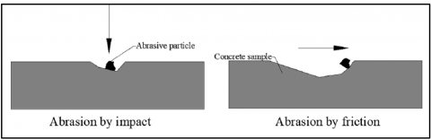
Abrasion occurs when particles such as sand or gravel strike the concrete surface; chemical attack refers to deterioration caused by chemical reactions with concrete components; and cavitation results from the collapse of vapor bubbles due to rapid pressure changes [1]. Stilling basins, spillway aprons, and culverts are among the critical hydraulic structures that are particularly susceptible to severe abrasion erosion [1], as illustrated in Figure 1.
Figure 1. There are two primary categories of abrasion wear.
Stilling basins and spillway aprons are hydraulic structures that are highly vulnerable to abrasion damage. Cracks and surface weakening result from shearing stresses caused by solid particles rolling or sliding on horizontal surfaces or directly impacting on vertical surfaces. In extreme cases, the depth of abrasion damage can range from a few centimeters to over one meter [1, 2]. Concrete characteristics such as strength, aggregate hardness, cement type, and water-cement ratio are among the many variables that influence abrasion erosion in hydraulic structures [3, 4]. The abrasion rate in hydraulic structures is influenced by material properties, transported solid characteristics, and water flow velocity. The rate of wear on structures is increased when water speeds are higher and when certain solid movement patterns are present [5, 6].
Dams and other hydraulic structures are vulnerable to abrasion erosion, which can cause expensive and difficult repairs. Enhancing concrete quality and conducting abrasion resistance testing, along with hydraulic modeling studies, are essential strategies for improving design and accounting for site-specific hydraulic conditions [1, 7]. Bridges and dams constructed with hydraulic concrete are prone to abrasion damage from sediment-laden water flow, which in turn reduces their service life. Particle size, flow rate, impact angle, exposure time, and concrete quality are important design and maintenance considerations for abrasion [8].
Abrasion by sediment-laden water is a common cause of damage to hydraulic concrete structures, reducing their lifespan. Particle size, velocity of flow, impact angle, duration of exposure, and quality of concrete are crucial considerations [9, 10].
Some experimental methods were developed to measure the abrasion rates of hydraulic concrete structures and to identify critical elements impacting abrasion damage [11, 12]. For example, ASTM C418 specifies the use of standardized Ottawa sand for sandblasting concrete specimens [13, 14]. Although abrasion resistance can be evaluated in laboratory settings, such results may not accurately reflect field conditions involving silt-laden flows [6, 15]. One effective method for analyzing abrasion erosion is the "Waterborne Sand Test Method" developed by studies [16, 17]. The experimental study was carried out by study [16] to examine the effects of a smooth spillway versus a stepped spillway on the flow parameters of a type III stilling basin. Three distinct horizon slants-14.04°, 26.57°, and 51.34°-were provided via an adjustable slope flume. Data were recorded for both the stepped and smooth chutes. The utilized stairs were 38.1 mm in height. Various discharge flows were used. In addition, a bubble detection probe was used to assess the air concentrations. According to the results of the tests, type III stilling basins are better served by a stepped chute. The utilization of a stepped chute resulted in an increase in air concentrations and a decrease in entering velocities and tailwater levels.
Using the FLOW3D tool, Frizell and Svoboda [16] guided numerical work that was based on the experimental work of Peng et al. [17]. The primary objective of the study was to evaluate the impact of a stepped chute on the hydraulic performance of a Type III stilling basin. Eight different flow discharges were tested using two chute slopes of 14.04° and 51.34° with respect to the horizontal axis. The test results demonstrated that Computational Fluid Dynamics (CFD) is effective in evaluating the complex behavior of hydraulic jumps. The stepped chute significantly reduced the flow velocity within the stilling basin.
To investigate how stepped spillways dissipate extra kinetic energy, Edwards [18] performed experimental studies. A 55-degree stepped spillway model was created. The eight discharges used varied from 0.01 m3/sec to 0.045 m3/sec. The results indicated that the use of stepped spillways significantly increases energy dissipation. A significant factor in energy loss is the ratio of the depth of the flow over the spillway (yc) to the height of the step (h). They also showed that the number of steps influences energy dissipation.
In order to compare the flow characteristics of a smooth spillway with those of a stepped one in a type III stilling basin, Frizell and Svoboda [16] performed an experimental study. A variable slope flume was employed to generate three distinct horizon slants: 14.04°, 26.57°, and 51.34°. The stepped chute and the smooth chute were both measured. The utilized stairs had a height of 38.1 mm. Various flow releases were utilized. A venturi meter was used to ascertain this, while an ultrasonic sensor was employed to ascertain the depths entering the basin (D1) and leaving it (D2). There was also the use of a bubble detecting probe to measure air concentrations. The stepped chute appears to be a more suitable option for type III stilling basins, according to the test results. Using a stepped chute enhances air concentrations while decreasing entering velocities and decreasing tailwater levels. After reviewing the experimental work of Frizell and Svoboda [16], Peng et al. [17] used the FLOW3D tool to guide their numerical work. Examining how a stepped chute affected the efficiency of a type III stilling basin was the primary goal of this study. Two chute slopes, one at 14.04 degrees and the other at 51.34 degrees with respect to the horizon, were employed, along with eight distinct flow releases. The results of the tests proved that computational fluid dynamics (CFD) may be used to examine the complex behavior of the hydraulic jump's water flow. In addition, the flow velocity along the stilling basin was drastically lowered by the stepped chute. The dissipation of surplus kinetic energy over stepped spillways was the subject of experimental investigation by Edwards [18]. A model of a stepped spillway at an angle of 55 degrees was made. From 0.01 to 0.045 m3/sec, eight distinct discharges were used. The findings from this study demonstrated that spillway steps significantly enhance energy dissipation. The ratio of the depth of the flow that flows over the spillway (yc) to the height of the step (h) is a key factor in the energy loss. Plus, they demonstrated that it is also dependent on the total number of steps. In order to compare the flow characteristics of a smooth spillway with those of a stepped one in a type III stilling basin, Frizell and Svoboda [16] performed an experimental study. A variable slope flume was employed to generate three distinct horizon slants: 14.04°, 26.57°, and 51.34°. The stepped chute and the smooth chute were both measured. The utilized stairs had a height of 38.1 mm. Various flow releases were utilized. A venturi meter was used to ascertain this, while an ultrasonic sensor was employed to ascertain the depths entering the basin (D1) and leaving it (D2). There was also the use of a bubble detecting probe to measure air concentrations. The stepped chute appears to be a more suitable option for type III stilling basins, according to the test results. Using a stepped chute enhances air concentrations while decreasing entering velocities and decreasing tail water levels. After reviewing the experimental work of Frizell and Svoboda [16], Peng et al. [17] used the FLOW3D tool to guide their numerical work. Examining how a stepped chute affected the efficiency of a type III stilling basin was the primary goal of this study. Two chute slopes, one at 14.04 degrees and the other at 51.34 degrees with respect to the horizon, were employed, along with eight distinct flow releases. The results of the tests proved that computational fluid dynamics (CFD) may be used to examine the complex behavior of the hydraulic jump's water flow. In addition, the flow velocity along the stilling basin was drastically lowered by the stepped chute. The dissipation of surplus kinetic energy over stepped spillways was the subject of experimental investigation by Edwards [18] and Luangcharoenrat et al. [19]. A model of a stepped spillway at an angle of 55 degrees was made [20]. From 0.01 to 0.045 m3/sec, eight distinct discharges were used. The findings from this study demonstrated that spillway steps significantly enhance energy dissipation [21, 22]. The ratio of the depth of the flow that flows over the spillway (yc) to the height of the step (h) is a key factor in the energy loss. Plus, they demonstrated that it is also dependent on the total number of steps. The impact of the water-to-cementitious-materials ratio on abrasion damage was investigated by Lehne and Preston [23]. The test looked at four different ratios: 0.54, 0.45, 0.33, and 0.28. As the results of the tests showed, the abrasion resistance is clearly reduced with an increase in the w/c ratio. Additionally, the results demonstrated that both class F fly ash concrete and conventional concrete were similarly affected by the w/c ratio in terms of abrasion resistance. At 28 days of age, the abrasion resistance of fly ash-free concrete increased by 203% when the water-to-cement ratio was decreased from 0.54 to 0.28. To determine how the w/c ratio affected concrete's wear loss, Zhang et al. [24] conducted an experiment. The same amount of material was used to make samples of 150×150×150 mm, but different water-to-cement ratios ranging from 0.33 to 0.5 were used. After 28 days of cure, the tests were carried out utilizing the water sand blast method. The abrasion loss was 0.962, 1.070, 1.126, 1.166, and 1.205 mm for (w/c) ratios of 0.33, 0.36, 0.4, 0.46, and 0.5, respectively, according to the test findings. These findings confirm that increasing the water-to-cement ratio significantly reduces the abrasion resistance of concrete.
Zhang et al. [24] stated that in order to learn more about recycled concrete (RC), recycled coarse aggregate (RCA), recycled fine aggregate (RFA), and recycled powder (RP) were mixed to make fully recycled aggregate concrete (FRAC). This made it possible to recycle more concrete waste. This study looked at recycled aggregates as separate combinations of aggregates instead of partial replacements. They made four combinations of aggregates using both natural and recycled aggregates. The impact of various aggregate combinations on the long-term mechanical and shrinkage characteristics of concrete was analyzed. Additionally, the impact of employing RP on the characteristics of FRAC was examined. The results showed that using fully recycled aggregate (FRA) combinations had a negative effect on the long-term mechanical and shrinkage properties of concrete. This supports what other studies have found about recycled concrete. Whatever the case, it was found that the FRA combination had a bigger effect than the fully recycled coarse aggregate and fully recycled fine aggregate combined. The mechanical properties of FRAC were also lowered by 5% to 17% when RP was added. Over 180 days, the shrinkage strain of FRAC was lowered by 3% to 13% as the RP content rose from 10% to 30%. Adding modification coefficients for aggregate combinations and RP contents to existing models led to the creation of a long-term shrinkage model that works for FRAC.
Ying et al. [25] stated that it is discussed how well recycled aggregate concrete (RAC) parts work when the water-to-cement ratio and the rate of replacing coarse aggregate with recycled aggregate change. Changing the replacement rate of RCA affects concrete strength; hence, the water—cement ratio must be changed simultaneously to fulfill strength requirements. So, the axial compressive strengths of the prism with 25 mix proportions, the short-term mechanical properties of reinforced concrete beams, and the long-term deformation properties were studied by changing the ratio of water to cement and the rate of RCA replacement. We used Digital Image Correlation (DIC) to find out the samples' bearing capacity and strain nephograms under different loads. For long-term deformation analysis, we made our own gravity loading apparatus and used it. The damage pattern of RAC was similar to natural aggregate concrete (NAC), but brittleness was greater [26]. Adjusting the RCA replacement rate reduces concrete brittleness before failure better than the water—cement ratio. The water-cement ratio affects the axial compressive strength and early creep of concrete. On the other hand, the RCA replacement rate affects the long-term deformation of a concrete beam.
Examining hydraulic systems' susceptibility to abrasion erosion is the primary goal of this research, which will center on SCC abrasion in particular. Hence, the following are the primary goals that are intended to be accomplished:
Secondly, we want to test both fibrous and plain SCC to see how they do under abrasion. To achieve this goal, a variety of SCC combinations were mixed using varying amounts of steel fibers and concrete grades. Using the conventional underwater test protocol, we examined the abrasion erosion of the cast specimens. Further, the impact effect was also replicated using the water jet test approach.
2.1 Introduction
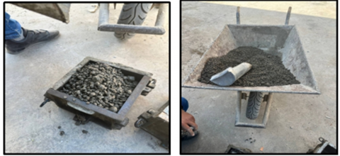
The experimental program includes the preparation of samples made from concrete, asphalt, and recycled materials, as well as specimens composed of ordinary Portland cement, sand, and gravel. The selection and preparation of all materials were conducted in detail.
The experimental work involved the preparation and casting of concrete specimens composed of Portland cement, sand, and gravel.
In addition, recycled materials consisting of asphalt mixed with cement were investigated and compared with conventional concrete. The potential of cement–asphalt concrete as a substitute for conventional solid concrete was also examined. The physical and mechanical properties of both conventional and recycled concrete were evaluated.
2.2 The experimental practical program
Hydraulic structures subjected to high-velocity water flow and varying flow inclination angles experience significant reductions in service life, making the classification of concrete corrosion resistance essential. Therefore, an in-depth evaluation was conducted in line with the study objectives and the current state of research on concrete corrosion resistance under hydraulic conditions. In this study, a total of 18 samples, including both recycled and conventional concrete, were prepared as part of an experimental program designed to evaluate performance under specific testing conditions.
After collecting samples and evaluating them at 7 and 28 days of age, the mixes were planned and prepared with a compressive strength rating of 30 MPa, as indicated in Table 1. To determine the structures' corrosion resistance, water flow was used [9]. The effect of flow inclination angle on the concrete surface was also investigated within the hydraulic test setup.
Table 1. The properties of cement used in this research
|
No. |
Oxide% |
Cement |
|
1 |
SiO2 |
21.04 |
|
2 |
Fe2O3 |
5.46 |
|
3 |
Al2O3 |
2.98 |
|
4 |
CaO |
63.56 |
|
5 |
MgO |
2.52 |
|
6 |
SO3 |
2.01 |
|
7 |
f-CaO |
0.76 |
|
8 |
LOSS on ignition% |
1.38 |
|
9 |
Specific Surface (M2/Kg) |
362 |
|
10 |
Specific Gravity |
3.15 |
2.3 Materials
In this study, 18 concrete samples were made using ordinary Portland cement of the R42.5 type. The parameters of the cement are displayed in Table 2, which also indicates the fine aggregate used, which was crushed gravel and local sand.
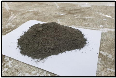
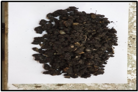
The samples consist of the asphalt concrete mixture, which consists of raw materials and recycled damaged materials, as shown below:
Figure 2. The sample of the Portland cement of the R42.5 type
Table 2. Proportions of concrete mixtures
|
Material |
C25 |
C30 |
|
Cement |
350 |
400 |
|
Sand |
700 |
800 |
|
Graved |
1150 |
1200 |
|
Water |
227 |
260 |
Figure 3. Sample of the damaged asphalt recycled
Figure 4. Crushing the concrete cubes, grinding them, and then sifting them through sieve No. (10)
2.4 Types of concrete mixtures used in the study
Mixes number 2 and different proportions were adopted to obtain yield strength of 30 MPa. In this work, Table 3 shows the weights of the components per cubic meter. The specific ratio is calculated based on the proportions of concrete mixtures such as C25 (25%) and C30 (30%). This means the recycled concrete replacement is 25% and 30%.
With varying percentages of recycled coarse aggregate to dolomite as replacements, some distinct concrete mixes were made: twenty-five percent, fifty-fifty, and one hundred percent. Then, three distinct curing techniques—open air, saturated, and painted—were applied to the four mixtures. After the curing period, tests were carried out on the hardened concrete to ascertain its mechanical qualities and other characteristics.
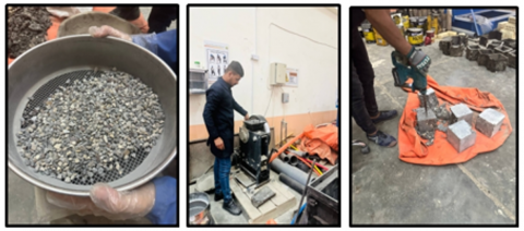
Figure 5 shows the steps used to prepare samples for this optional task. The samples were taken out of the mold after 24 hours and placed in a treatment tank with water at 25 degrees Celsius. The test was conducted at the expected dates for 7 days of age and 28 days of age to ensure accuracy.
Figure 5. The mixture of materials sample
Table 3 shows the results of the examination for the samples and ages shown above and for the resistance to C30 Compression.
Table 3. The results of the examination for the samples, ages, and resistance to C30 compression
|
Test Results for Asphalt Concrete |
Test Results for Normal Concrete |
The Age of Sample |
|
26.17 |
24.63 |
7 days |
|
28.36 |
26.04 |
|
|
26.24 |
26.04 |
|
|
26.923 |
25.816 |
Average |
|
35.127 |
32.019 |
28 days |
|
35.450 |
33.852 |
|
|
37.485 |
34.540 |
|
|
33.470 |
36.020 |
Average |
2.6 Water flow corrosion test
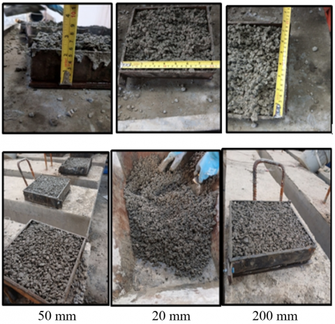
In order to simulate the corrosion that occurs in hydraulic structures resulting from the impact of transported sediments, 36 samples of square plates with dimensions (50 mm, 200 mm, and 200 mm) were tested, as shown in Figure 6, where the samples were selected for ages (2, 7, and 28) days with dimensions (50 mm, 20 mm, and 200 mm) samples.
Figure 6. The dimensions (50 mm, 20 mm, and 200 mm) samples
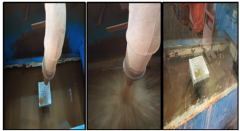
At a water velocity of 10m/sec through the rectangular nozzle, as shown in Figure 7.
Figure 7. 0.6 mm distilled sand was used as graded sand
Graded sand measuring 0.6 mm was utilized after the samples were attached at inclination angles of 45° and 90°, as illustrated in Figure 7. With a concentration of 30 kg/m3, the water contained sand. Next, the concrete samples were swapped out and left to undergo corrosion testing for three hours or 180 minutes. Concrete and normal concrete were subjected to a resistance test. Figure 7 depicts the process of aqueous corrosion utilizing materials that were previously produced in the laboratory of Wasit University's College of Engineering. Scraping or corroding the concrete is seen in the machine diagram. We tested the corrosion after the first test. The measured samples' weight, both before and after 8 hours of drying at 110℃, are reordered to account for the effects of corrosion.
2.7 Abrasion test
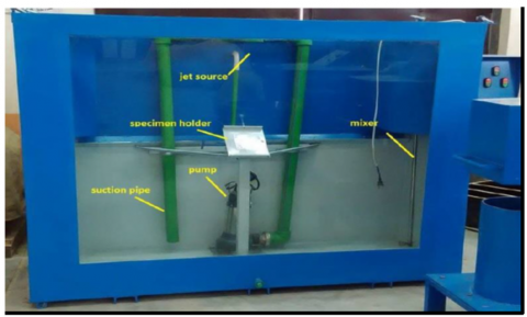
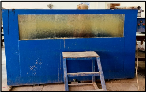
As demonstrated in Figure 8, the water-jet testing system is used to experimentally mimic the abrasion of inclined surfaces in hydraulic structures [9].
Figure 8. The used water-jet testing machine
This study investigated the potential of the water jet test to simulate the abrasion of the recycled concrete samples of hydraulic systems. We studied 200×200×50 mm plate samples that were submerged in direct high-pressure water to mimic the wear and tear that happens when sediments are moved through hydraulic systems. The test was conducted nine times at one-hour intervals. The abrasion test was run for nine hours on the specimens. The weight of the sample was recorded after each step. A high-pressure test method is employed to pump water containing erodent materials from a 1 m³ tank using a 200×10 mm nozzle. In this case, we conducted the test using the same procedures but with a circular nozzle with a diameter of 50 mm. At a velocity of 20 m/s, the water jet eroded 30 kg/m³ of graded sand. The tank used for testing water jet abrasion in the experiment can be observed in Figure 8.
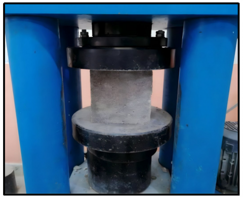
Lastly, the machine for testing compressive strength is shown in Figure 9.
Figure 9. Compressive strength test machine
The asphalt concrete surface of roads is particularly vulnerable to damage during extended periods of rain and throughout the spring and fall, when there are frequent changes in temperature from freezing to thawing. As a result of the flaking of mineral particles from the pavement, such damage typically appears as a multitude of scattered corrugations. These flaws occur because asphalt concrete does not have enough resistance to water and frost [27, 28]. Adopting asphalt concrete that possesses adequate resistance to air corrosion is a key component in prolonging the lifespan of the road surface. The parameters that define the performance of asphalt concrete pavement in the most adverse weather conditions—the fall and spring—are the markers of long-term water saturation and frost resistance of asphalt concrete samples, which are crucial indicators of the material's corrosion resistance.
Due to the presence of water in the asphalt concrete pores, the structural connections at the boundary of the "binder-mineral material" phase interface weaken. In the presence of water, bitumen coatings are seen to peel from the stone's surface. Coating flaws such as fracture networks and asphalt concrete particle spalling from the surface are consequently formed [29, 30]. Overlying layers of asphalt concrete must, therefore, be very resistant to water and frost.
3.1 Assessment of the abrasion resistance of asphalt concrete
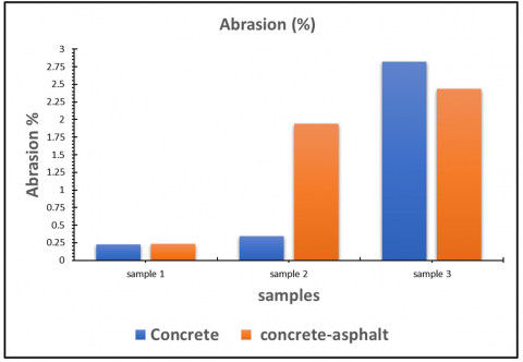
Table 4 presents the weight of specimens before and after abrasion for 2 days and at an angle of 45° for specimens with square dimensions of 200 × 200 × 50, concrete, and recycled asphalt concrete, according to the data shown below regarding the relationship between the percentage of abrasion rate and age.
Table 4. The weight of specimens before and after abrasion for 2 days at an angle of 45°
|
|
Concrete Specimens |
Concrete-Asphalt Specimens |
||||
|
|
Weight before (Kg) |
Weight After (Kg) |
Corrosion % |
Weight Before (Kg) |
Weight After (Kg) |
Corrosion % |
|
Sample 1 |
3.4927 |
3.4849 |
0.223 |
4.4247 |
4.4145 |
0.230 |
|
Sample 2 |
3.0473 |
3.0368 |
0.344 |
4.9844 |
4.8877 |
1.940 |
|
Sample 3 |
3.5452 |
3.4453 |
2.817 |
4.5242 |
4.4140 |
2.435 |
|
|
Average |
1.128% |
Average |
1.535% |
||
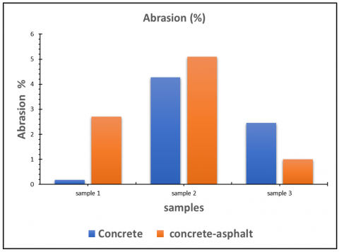
Table 4 explains the comparison between concrete specimens and the concrete-asphalt specimens. The weight before and after was recorded for different samples, and the corrosion percentage was calculated. It was found that the highest corrosion percentage was in the third specimen, and the corrosion rate was found to be 1.128%. The results from the concrete-asphalt specimens were obtained to be the highest for the last sample, and the average corrosion was found to be higher than that of the concrete samples.
Figure 10 shows the relationship between samples and abrasion percentage. It expressed that the first specimens expressed the abrasion percentage for the first specimens. The second specimen showed that there is no difference between concrete and the concrete-asphalt samples. According to the third sample, it was found that the abrasion for concrete was less than that of concrete-asphalt.
Figure 10. The relation between abrasion and samples
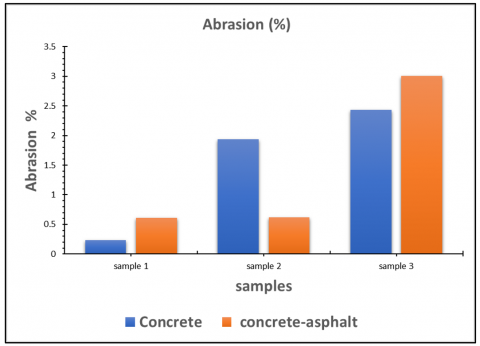
Table 5 expresses the comparison between concrete and concrete-asphalt specimens, and the results show that there is a difference in the corrosion percentage between the concrete and concrete-asphalt samples. The third specimen was found to be the highest one, and the same was observed for both concrete and concrete-asphalt.
Table 5. The weight of specimens before and after abrasion for 2 days at an angle of 90°
|
|
Concrete Specimens |
Concrete-Asphalt Specimens |
||||
|
|
Weight Before (Kg) |
Weight After (Kg) |
Corrosion % |
Weight Before (Kg) |
Weight After (Kg) |
Corrosion % |
|
Sample 1 |
3.4865 |
3.4654 |
0.608 |
4.5955 |
4.4961 |
2.163 |
|
Sample 2 |
3.6589 |
3.6362 |
0.620 |
4.0776 |
4.0034 |
0.748 |
|
Sample 3 |
3.5662 |
3.4589 |
3.008 |
4.4568 |
4.3255 |
2.946 |
|
|
Average |
1.412% |
Average |
1.952% |
||
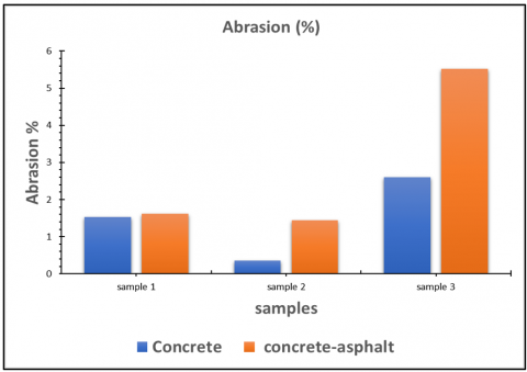
Figure 11 shows the relation between samples and the abrasion rate at 90 degrees and for two days. It was found that there was a variation between the first and second samples. It is shown that the abrasion rate was the highest for the third sample, while the second sample exhibited a lower abrasion rate for concrete. The abrasion rate for asphalt-concrete was highest in the third sample.
Figure 11. The relation between samples and corrosion rate at a 90° angle and for 2 days
Table 6 expresses the comparison between concrete and concrete-asphalt for different samples. The weight was found to be increased after corrosion for both types of concrete. The differences between concrete and concrete-asphalt were recorded based on the differences in weight before and after abrasion.
Table 6. The weight of specimens before and after abrasion for 7 days, and at an angle of 45°
|
|
Concrete Specimens |
Concrete-Asphalt Specimens |
||||
|
|
Weight Before (Kg) |
Weight After (Kg) |
Corrosion% |
Weight Before (Kg) |
Weight After (Kg) |
Corrosion % |
|
Sample 1 |
7.757 |
7.7429 |
0.181 |
5.1106 |
4.9722 |
2.7080 |
|
Sample 2 |
4.6144 |
4.4173 |
4.271 |
4.9294 |
4.6390 |
5.0911 |
|
Sample 3 |
4.4265 |
4.3178 |
2.455 |
4.9869 |
4.9369 |
1.002 |
|
|
Average |
2.302 |
Average |
3.207% |
||
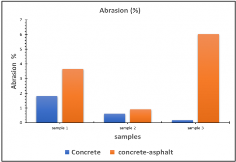
Figure 12 shows the relation between the specimens and the abrasion rate at 45 degrees for 2 days. It was found that there were differences between concrete and concrete-asphalt for different samples. The first sample expressed the moderate abrasion rate, the highest abrasion rate was found for the third sample, and the lowest abrasion rate was found for the first sample.
Figure 12. The relation between the specimen and the abrasion rate at a 45° angle and for 2 days
Table 7 expresses the weight of specimens before and after abrasion rate at an angle of 90 degrees for 7 days. The differences in weight between before and after corrosion were clearly obvious.
Table 7. The weight of specimens before and after abrasion for 7 days at an angle of 90o
|
|
Concrete Specimens |
Concrete-Asphalt Specimens |
||||
|
|
Weight Before (Kg) |
Weight After (Kg) |
Corrosion % |
Weight Before (Kg) |
Weight After (Kg) |
Corrosion % |
|
Sample 1 |
4.9806 |
4.900 |
1.618 |
4.7422 |
4.6696 |
1.530 |
|
Sample 2 |
5.0666 |
4.9937 |
1.438 |
4.6997 |
4.6831 |
0.353 |
|
Sample 3 |
5.1299 |
4.8464 |
5.526 |
4.2178 |
4.1080 |
2.603 |
|
|
Average |
2.860% |
Average |
1.495% |
||
In Figure 13, the relation between samples and corrosion rate was found for three different samples. For sample one, the abrasion rate was found to be the highest one for concrete-asphalt compared to the concrete sample. The third sample was found to have the highest corrosion rate. Besides, the results indicate that the concrete-asphalt was better in performance compared to the normal concrete.
Figure 13. The relation between samples and corrosion rate for 7 days at a 90° angle
In Table 8, the results showed that the weights before and after for both concrete samples and concrete-asphalt concrete were indicated for three different samples. The corrosion rate was different for different samples. The first sample was 3.6% for concrete, while it was 1.8% for concrete-asphalt specimens. The average corrosion rate for both concrete and concrete-asphalt specimens was different. Various results were dedicated to both before and after of weight for both types of concrete. The results indicated that the concrete-asphalt was better in the performance for concrete-asphalt than concrete samples.
Table 8. The weights of specimens before and after abrasion for 28 days at an angle of 45°
|
|
Concrete Specimens |
Concrete-Asphalt Specimens |
||||
|
|
Weight Before (Kg) |
Weight After (Kg) |
Corrosion % |
Weight Before (Kg) |
Weight After (Kg) |
Corrosion % |
|
Sample 1 |
4.9096 |
4.7300 |
3.658 |
4.4257 |
4.3455 |
1.812 |
|
Sample 2 |
4.0470 |
4.0102 |
0.909 |
4.7482 |
4.7190 |
0.614 |
|
Sample 3 |
4.9612 |
4.6615 |
6.040 |
4.1644 |
4.1575 |
0.165 |
|
|
Average |
3.535% |
Average |
0.863% |
||
Figure 14 shows the relation between abrasion and specimens for 28 days at an angle of 45 degrees. It was found that the concrete specimens have the lowest corrosion rate for 28 days at an angle of 45 degrees. The corrosion rate was found to be the highest one for third sample and the corrosion rate was found to be the highest. The results indicated that the concrete-asphalt showed better performance based on the data above.
Figure 14. The relation between abrasion and specimens for 28 days at an angle of 45°
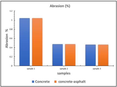
In Table 9, the results showed the weights of specimens for both types of concrete and concrete-asphalt for different samples. The data was expressed for 28 days at an angle of 90 degrees. The corrosion rate was found to be equal to 0.663% for the concrete sample, and it was equal to 0.6196% for the concrete-asphalt samples. Various values of different weights were observed for both types of concrete, and the data was conducted for 28 days and at an angle equal to 90 degrees.
Table 9. The weights of specimens before and after abrasion for 28 days at angles of 90°
|
Concrete Specimens |
Concrete-Asphalt Specimens |
||||
|
Weight Before |
Weight After |
Corrosion % |
Weight Before |
Weight After |
Corrosion % |
|
5.1080 |
5.0546 |
1.045 |
4.6670 |
4.6163 |
1.086 |
|
5.1396 |
5.1150 |
0.478 |
4.6832 |
4.6685 |
0.313 |
|
5.0958 |
5.0720 |
0.467 |
4.6440 |
4.6226 |
0.460 |
|
Average |
0.663% |
Average |
0.6196% |
||
From Figure 15, the results showed the relation between samples and the abrasion rate. The abrasion rate of the third sample was determined to be lower than that of the first sample. The initial sample exhibited the highest average rate compared to the other samples, signifying that the concrete-asphalt specimens demonstrated superior performance after 28 days. The comparison between two distinct types of concrete demonstrated superior performance compared to others.
Figure 15. The relation between abrasion and specimens for 28 days at an angle of 90°
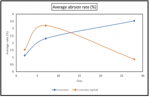
Figure 16 expressed the relation between the average abrasion rate and the days at different various rates (2 days, 7 days, and 28 days) for 45 degrees. For concrete, the average rate was found to increase after 28 days for concrete-asphalt. However, the concrete was found to decrease after 28 days. The results showed better performance for concrete-asphalt compared to concrete. The various days were investigated in this research and for testing the results for 45 degrees.
Figure 16. The abrasion average rate between concrete and concrete-asphalt samples of 45°
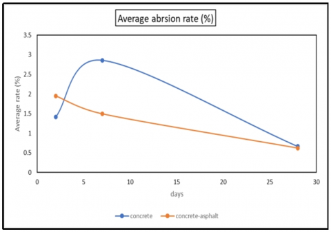
The results demonstrated that concrete-asphalt performed better for different days, as shown in Figure 17. A two-day drop was followed by a seven-day drop, and finally, a 28-degree drop in the average rate for concrete and asphalt was seen. Performance was better at 28 days compared to 2 or 7 days. In contrast, after 2 and 7 days, the concrete's average rate of abrasion increased, and after 28 days, it decreased. When tested at 90 degrees, the concrete-asphalt mixture outperformed regular concrete.
Figure 17. The abrasion average rate for both concrete and concrete-asphalt samples of 90°
People are seeking a pleasant existence with safe housing and well-connected roads for transit, which is driving urbanization today [30, 31]. People rely significantly on natural resources to fulfill these fundamental requirements. This reliance leads to the depletion of natural resources. Cement, aggregates, and water are three of the most common building materials. To solve the aforementioned problem, we need to use industrial ecology, which involves reusing materials from one industry to feed another [32]. In the case of aggregates, this research investigates potential substitutes for the already accessible natural resources. Recycling aggregates, such as RCA, mining waste, such as iron ore tailings, and infrastructure debris, such as RAP, make up the bulk of these alternative resources. The most up-to-date research on RAP as a resource replacement is the subject of this article. Steel output increased due to its increased use as reinforcement in concrete, which gives ductility to the concrete components used in construction [33]. The country of India ranks fourth in the world for steel manufacturing. A recent study found that Malaysia produces an alarming 625,000 metric tons of IOT annually, posing a major threat to the environment. The environmental harm caused by IoT has prompted the government of Karnataka, India, to consider banning it. Iron ore tailings are a byproduct of the steelmaking process. The growth in steel manufacturing has made the disposal of these tailings a challenge [34]. It ends up in rivers, oceans, quarries, and landfills as trash. In response to these issues and the subsequent rise in waste production, studies are underway to investigate the feasibility of using tailings in place of fine aggregates in concrete and masonry bricks [35]. The concrete remnants of demolished buildings, highways, and airport runways are called Recycled Concrete Aggregates (RCA). The RCA are often diverted from landfills and reused in new concrete as aggregates [36].
More and more roads are being built using recycled concrete aggregate (RCA) these days. Seven hundred fifty million cubic meters of aggregates would be needed to accomplish the road sector's goals. One of the most important aspects of rural development is road connectivity, which increases agricultural income and creates productive jobs by improving access to social and economic services [37]. The future's materials are recycled aggregates. To perhaps solve these environmental and economic problems, recycled concrete aggregate (RCA) can be used in place of virgin aggregates. The cost-effectiveness and strength of concrete incorporating crushed and granulated coconut and palm kernel shells were evaluated in comparison to conventional coarse aggregates [38]. The overarching goal of this research is to promote the use of agricultural waste materials in the development of affordable housing solutions [39]. The following ratios of crushed granular coconut and palm kernel were utilized to make 1:1:2 and 1:2:4 mixes in place of typical coarse aggregate: 0%, 25%, 50%, 75%, and 100%. The physical and mechanical parameters of 320 cast cubes were determined [40, 41]. When the two mix ratios were compared, it was seen that as the percentages of coconut shell and palm kernel shell went up, the compressive strength of the concrete went down. Concrete made from palm kernel shell and coconut shells both have significant cost reductions: 42% and 30%, respectively. Researchers [11, 42] looked at using a mix of ground palm kernel and coconut shell as a concrete aggregate substitute. In place of the coarse aggregate, the researchers used ground palm kernel and coconut shell in their investigation. From 0% to 100%, 25%, 50%, and 75% of the original material was replaced by coconut shell. The combination of these components shows promise as a lightweight aggregate for concrete and as a means to lower building material costs.
Gonzalez-Fonteboa et al. [43] investigated the use of palm kernel shells (PKS) and sawdust as a substitute for aggregate. Sawdust and palm kernel shells are used as coarse and fine aggregates, respectively, in reinforced concrete slabs. For each of the five levels of conventional aggregate replacement—0%, 25%, 50%, 75%, and 100%—sawdust and PKS were used in the same proportions [44]. We measured the compressive and flexural strengths at various times. Used in applications requiring low stress and cost-effectiveness, lightweight, reinforced concrete slabs made with 25% sawdust and PKS were discovered. Using sawdust/PKS can reduce the cost of producing slabs by 7.43% per cubic meter.
A key component of modern sustainable concrete, according to study [45], is the lightweight aggregate. Reduced transportation needs, optimized structural efficiency leading to less overall building material consumption, energy conservation, decreased labor demand, and increased life of structural concrete are all ways in which lightweight aggregates contribute to sustainable development. In study [42, 46], the researchers investigated the characteristics of reinforced concrete made from recycled coconut shells. As part of their experiment, they substituted fly ash and coconut shells for conventional coarse aggregates. A 10%, 15%, and 20% replacement rate with coconut shell was achieved, whereas 5% and 25% replacement rates with fly ash were recorded. According to his research, the more CS that were replaced, the less workable the material became. When compared to control concrete, CS concretes had weaker compressive and split tensile strengths. In the experimental study by Osei [47], coconut shells are used as aggregate in concrete to a lesser extent than coarse aggregate. A complete substitution of coconut shell was achieved at 100% after 0%, 20%, 30%, 40%, and 50%. He came to the conclusion that CS may be utilized to make lightweight concrete and that structural concrete can be made with 18.5% crushed coconut shells instead of granite. Improving concrete’s compressive strength using coconut shells developed three distinct mix designs for concrete grades M20, M35, and M50. The percentages of coconut shells that were used as a substitute ranged from 0% to 40%. The results showed that after 28 days, M20 grade concrete cubes that were 30% replaced with CS aggregates had strength of 23 MPa. A 28-day strength of 42 MPa for M35 was achieved by concrete cubes that had 30% CS aggregates by weight. Concrete cubes of M50 grade, reinforced with 30% CS aggregates, demonstrated a strength of 51 MPa after 28 days. In the study [48], which was published in 2014, in which investigated the properties of coconut shell and concrete that was made with coconut shell aggregate. The concrete used is of the M30 grade. Workability, compressive, flexural, and split tensile strength tests were among those that were carried out. Using a standard 1:2:4 ratio, different mixes were made by using different amounts of coarse aggregate and coconut shells: 0%, 25%, 50%, and 100%. The cube samples made of coconut shells with different amounts of coarse aggregate have compressive strengths of 24, 22.62, 14.93, and 5.48 MPa and flexural strengths of 4.32 and 2.4 N/mm². In light of the information presented above, it is clear that CSC with 25% coarse aggregate replacement has properties similar to the nominal mix, while CSC with 50% replacement has properties similar to lightweight concrete. According to Kambli and Mathapati [46], who published an article titled “Application of Coconut Shell as Coarse Aggregate in Concrete”, they tested the effects of using 0%, 10%, 20%, and 30% coconut shell as fine and coarse aggregates in M20 concrete for 7, 28, and 56 days. Researching the compressive strength, split tensile strength, and density of concrete that contains coconut shell as a partial aggregate replacement is the primary goal of this study. Another objective is to raise awareness about the possibility of using coconut shells this way. This study found that coarse aggregates made from coconut shells can have a coconut shell replacement rate of up to 10–12%. We also found that when the percentage of coconut shell in concrete increases, its compressive strength and split tensile strength decrease, while its workability increases. We can see that the concrete that has 20% coconut shell added to it has good strength here. One solution to social and environmental problems is the use of agricultural waste in concrete. This waste can replace conventional aggregate sources, which are quickly depleting, and help build better communities. The purpose of this study is to examine previous research on recycling coconut husks into concrete, discuss the challenges associated with disposing of garbage, and address the scarcity of traditional building materials. It has been determined that when substituted for conventional coarse aggregate in concrete production, coconut shells are a better choice as a lightweight aggregate with low strength-giving properties.
In a 1993 publication [49], this investigated rubberized concrete’s compressive and tensile strengths using rubber tire particles as coarse aggregates. He points out that regular concrete fared better than rubberized concrete when subjected to multiple freeze-thaw cycles. Although its compressive and tensile strengths were lower than those of regular concrete, rubberized concrete could soak up a lot of plastic energy when subjected to such stresses. Instead of the usual brittle breakdown, it showed signs of ductile plastic failure.
Toutanji [50] stated that the rubber tire aggregate was used in cement concrete to study the effects of replacing mineral coarse aggregate. The greatest size of the shredded rubber tires employed was 12.7mm, and their specific gravity was around 0.61. These rubber tire chips showed a decrease in compressive and flexural strength when added to concrete. The specimens that were mixed with rubber tire aggregate showed signs of ductile failure and were significantly displaced before breaking. Both plain concrete and rubber tire concrete specimens had their flexural toughness tested. When compared to the control specimens, those that contained rubber tire chips demonstrated a high level of toughness. Recycled aggregate has many modern-day uses in the building industry. Each country has its own unique set of apps. Many sources, including construction and demolition sites, RMC factories, and others, make recycled aggregates readily available in big quantities. Carrying recycled materials to processing facilities can save energy use. This is primarily due to the fact that processing, manufacturing, and use can all occur on a construction site. Recycled aggregate is less expensive than new material. The price for the natural aggregate utilized in the building projects is around 1.5 times higher. Because recycled aggregate is lighter than raw aggregate, it may be transported at a lower cost. There is a vast market for recycled concrete aggregate. The Environmental Council of Concrete Organization states that recycled concrete aggregate has several potential applications, including but not limited to residential driveways, concrete shoulders, bridge substructures and superstructures, curbs, sidewalks, and general and structural fills. Additionally, it was noted that sub-bases and support layers, including permeable bases and unsterilized bases, can make use of recycled concrete aggregate.
Factors influencing abrasion resistance, such as aggregate type, water-cementitious materials ratios (w/cm), and others, were studied in this study along with the abrasion resistance of concrete-asphalt. Recycling concrete means making something new out of the debris left behind after a building's demolition. Transporting debris to a landfill is pricier and harmful to the environment than recycling. Gravel for roads, revetments, retaining walls, landscaping, and fresh concrete can all be made from crushed rubble. Bricks or slabs made from large sections can be utilized, or urbanite, a substance that can be mixed with fresh concrete, can be built into structures. There is now just a small market for reusing blocks in their original shape or by breaking them into smaller pieces, which has an even lower environmental impact. This application could be enhanced with better architectural designs that enable the reuse of slabs and the modification of buildings without demolition. Since their span is often constant and they are straightforward to disassemble, hollow-core concrete slabs are excellent for reuse. The researchers in this study created concrete and asphalt mixtures and studied them using various tests, including abrasion and compressive strength tests. According to the research's experimental findings, the asphalt concrete mixture has a lower corrosion rate at 7 and 28 days, as well as at 45 and 90 degrees, compared to the regular concrete mixture. This allows for the mixture with a resistance of 30 MPa to achieve satisfactory results. Reusing and recycling old materials will allow them to create smaller, more durable regulators or channels.
4.1 Recommendation
It is preferable to recycle damaged materials and rework them structurally and hydraulically for the following reasons:
1- Economical because it is less expensive.
2-To achieve a sustainable green environment.
3-To achieve high corrosion resistance.
We thank the construction laboratory in Wasit University for their support during the period of work.
[1] Horvath, A.(2004). Construction materials and the environment. Annual Review of Environment and Resources, 29: 181-204. https://doi.org/10.1146/annurev.energy.29.062403.102215
[2] Mansourimajoumerd, P., Mahdavinejad, M., Niknia, S., Shirvani, M. (2020). Comprehensive strategies for optimization e_Energy system in different climate zone. In the 4th International Conference on Architecture, Arts and Applications.
[3] Mansourimajoumerd, P., Bazazzadeh, H., Mahdavinejad, M., Nia, S.N. (2023). Energy efficiency and building’s envelope: An integrated approach to high-performance architecture. In Urban and Transit Planning: City Planning: Urbanization and Circular Development, pp. 25-33. https://doi.org/10.1007/978-3-031-20995-6_3
[4] Turkyilmaz, A., Guney, M., Karaca, F., Bagdatkyzy, Z., Sandybayeva, A., Sirenova, G. (2019). A comprehensive construction and demolition waste management model using PESTEL and 3R for construction companies operating in Central Asia. Sustainability, 11(6): 1593. https://doi.org/10.3390/su11061593
[5] Ménard, Y., Bru, K., Touzé, S., Lemoign, A., Poirier, J.E., Ruffié, G., Bonnaudin, F., von Der Weid, F. (2013). Innovative process routes for a high-quality concrete recycling. Waste Management, 33(6): 1561-1565. https://doi.org/10.1016/j.wasman.2013.02.006
[6] Tam, V.W.Y. (2008). Economic comparison of concrete recycling: A case study approach. Resources, Conservation and Recycling, 52(5): 821-828. https://doi.org/10.1016/j.resconrec.2007.12.001
[7] Al-Waked, Q., Bai, J., Kinuthia, J., Davies, P. (2022). Durability and microstructural analyses of concrete produced with treated demolition waste aggregates. Construction and Building Materials, 347: 128597. https://doi.org/10.1016/j.conbuildmat.2022.128597
[8] Shima, H., Tateyashiki, H., Matsuhashi, R., Yoshida, Y. (2005). An advanced concrete recycling technology and its applicability assessment through input-output analysis. Journal of Advanced Concrete Technology, 3(1): 53-67. https://doi.org/10.3151/jact.3.53
[9] Fatta, D., Papadopoulos, A., Avramikos, E., Sgourou, E., Moustakas, K., Kourmoussis, F., Mentzis, A., Loizidou, M. (2003). Generation and management of construction and demolition waste in Greece—An existing challenge. Resources, Conservation and Recycling, 40(1): 81-91. https://doi.org/10.1016/S0921-3449(03)00035-1
[10] Qaidi, S., Najm, H.M., Abed, S.M., Özkılıç, Y.O., Al Dughaishi, H., Alosta, M., Mentzis, M.M.S., Alkhatib, F., Milad, A. (2022). Concrete containing waste glass as an environmentally friendly aggregate: A review on fresh and mechanical characteristics. Materials, 15(18): 6222. https://doi.org/10.3390/ma15186222
[11] Tomosawa, F., Noguchi, T., Tamura, M. (2005). The way concrete recycling should be. Journal of Advanced Concrete Technology, 3(1): 3-16. https://doi.org/10.3151/jact.3.3
[12] Rajaei Lak, H., Rajabi, E., Ghodrati Amiri, G., Shakouri, A. (2023). Numerical analysis of regular reinforced concrete frames under near-fault ground motions. Iranian Journal of Science and Technology, Transactions of Civil Engineering, 47(1): 399-414. https://doi.org/10.1007/s40996-022-00990-y
[13] Mohammed Ali, A., Besharat Ferdosi, S., Kareem Obeas, L., Khalid Ghalib, A., Porbashiri, M. (2024). Numerical study of the effect of transverse reinforcement on compressive strength and load-bearing capacity of elliptical CFDST columns. Journal of Rehabilitation in Civil Engineering, 12(1): 106-126. https://doi.org/10.22075/jrce.2023.29167.1764
[14] Shima, H. (1999). New technology for recovering high quality aggregate from demolished concrete. In Proceedings of Fifth International Symposium on East Asia Recycling Technology, pp. 106-109.
[15] Tam V.W.Y. (2009). Comparing the implementation of concrete recycling in the Australian and Japanese construction industries. Journal of Cleaner Production, 17(7): 688-702. https://doi.org/10.1016/j.jclepro.2008.11.015
[16] Frizell, K.W., Svoboda, C.D. (2012). Performance of type III stilling basins-stepped spillway studies: Do stepped spillways affect traditional design parameters? US Department of the Interior, Bureau of Reclamation.
[17] Peng, C.L., Scorpio, D.E., Kibert, C.J. (1997). Strategies for successful construction and demolition waste recycling operations. Construction Management & Economics, 15(1): 49-58. https://doi.org/10.1080/014461997373105
[18] Edwards, B. (1999). Sustainable Architecture: European Directives and Building Design. Architectual Press.
[19] Luangcharoenrat, C., Intrachooto, S., Peansupap, V., Sutthinarakorn, W. (2019). Factors influencing construction waste generation in building construction: Thailand’s perspective. Sustainability, 11(13): 3638. https://doi.org/10.3390/su11133638
[20] Iida, K., Saeki, T., Nagataki, S. (2001). An integrated concrete recycling system including cement. Concrete Library International.
[21] Jawahir, I.S., Bradley, R. (2016). Technological elements of circular economy and the principles of 6R-based closed-loop material flow in sustainable manufacturing. Procedia Cirp, 40: 103-108. https://doi.org/10.1016/j.procir.2016.01.067
[22] Arrigoni, A., Panesar, D.K., Duhamel, M., Opher, T., Saxe, S., Posen, I.D., MacLean, H.L. (2020). Life cycle greenhouse gas emissions of concrete containing supplementary cementitious materials: Cut-off vs. substitution. Journal of Cleaner Production, 263: 121465. https://doi.org/10.1016/j.jclepro.2020.121465
[23] Lehne, J., Preston, F. (2018). Making concrete change: Innovation in low-carbon cement and concrete. Chatham House Report, 13.
[24] Zhang, H., Xiao, J., Tang, Y., Duan, Z., Poon, C. (2022). Long-term shrinkage and mechanical properties of fully recycled aggregate concrete: Testing and modelling, Cement and Concrete Composites, 130: 104527. https://doi.org/10.1016/j.cemconcomp.2022.104527
[25] Ying, J., Su, F., Chen, S. (2022). Long term performance of recycled concrete beams with different water—cement ratio and recycled aggregate replacement rate. Frontiers of Structural and Civil Engineering, 16: 302-315. https://doi.org/10.1007/s11709-022-0803-7
[26] Facts and figures about materials, waste and recycling. EPA. https://www.epa.gov/facts-and-figures-about-materials-waste-and-recycling.
[27] Jiang, G., Keller, J., Bond, P.L. (2014). Determining the long-term effects of H2S concentration, relative humidity and air temperature on concrete sewer corrosion. Water Research, 65: 157-169. https://doi.org/10.1016/j.watres.2014.07.026
[28] Afshinnia, K., Rangaraju, P.R. (2015). Influence of fineness of ground recycled glass on mitigation of alkali–silica reaction in mortars. Construction and Building Materials, 81: 257-267. https://doi.org/10.1016/j.conbuildmat.2015.02.041
[29] Saccani, A., Bignozzi, M.C. (2010). ASR expansion behavior of recycled glass fine aggregates in concrete. Cement and Concrete Research, 40(4): 531-536. https://doi.org/10.1016/j.cemconres.2009.09.003
[30] Jani, Y., Hogland, W. (2014). Waste glass in the production of cement and concrete–A review. Journal of Environmental Chemical Engineering, 2(3): 1767-1775. https://doi.org/10.1016/j.jece.2014.03.016
[31] Özalp, F., Yılmaz, H.D., Kara, M., Kaya, Ö., Şahin, A. (2016). Effects of recycled aggregates from construction and demolition wastes on mechanical and permeability properties of paving stone, kerb and concrete pipes. Construction and Building Materials, 110: 17-23. https://doi.org/10.1016/j.conbuildmat.2016.01.030
[32] Wang, L., Wang, J., Qian, X., Chen, P., Xu, Y., Guo, J. (2017). An environmentally friendly method to improve the quality of recycled concrete aggregates. Construction and Building Materials, 144: 432-441. https://doi.org/10.1016/j.conbuildmat.2017.03.191
[33] Katz, A. (2004). Treatments for the improvement of recycled aggregate. Journal of materials in civil engineering, 16(6): 597-603. https://doi.org/10.1061/(ASCE)0899-1561(2004)16:6(597)
[34] Shao, Y., Lefort, T., Moras, S., Rodriguez, D. (2000). Studies on concrete containing ground waste glass. Cement and Concrete Research, 30(1): 91-100. https://doi.org/10.1016/S0008-8846(99)00213-6
[35] Tomosawa, F., Noguchi, T., Tamura, M. (2005). The way concrete recycling should be. Journal of Advanced Concrete Technology, 3(1): 3-16. https://doi.org/10.3151/jact.3.3
[36] Fauzi, M.A., Sulaiman, H., Ridzuan, A.R.M., Azmi, A.N. (2016). The effect of recycled aggregate concrete incorporating waste paper sludge ash as partial replacement of cement. AIP Conference Proceedings, 1774(1): 030007. https://doi.org/10.1063/1.4965063
[37] Bui, N.K., Satomi, T., Takahashi, H. (2019). Influence of industrial by-products and waste paper sludge ash on properties of recycled aggregate concrete. Journal of Cleaner Production, 214: 403-418. https://doi.org/10.1016/j.jclepro.2018.12.325
[38] Sharipudin, S.S., Ridzuan, A.R.M., Mohd Saman, H. (2012). Performance of foamed concrete with waste paper sludge ash (Wpsa) and fine recycled concrete aggregate (Frca) contents. International Sustainability and Civil Engineering Journal, 1(2): 19-27.
[39] Chen, Z., Xu, J., Chen, Y., Jing, C. (2016). A case study on utilization of 50-year-old concrete in recycled aggregate. Journal of Residuals Science & Technology, 13(2): 147-152. https://doi.org/10.12783/issn.1544-8053/13/S2/19
[40] Jagan S, Neelakantan, T.R., Saravanakumar, P. (2021). Performance enhancement of recycled aggregate concrete–An experimental study. Applied Science and Engineering Progress, 15(1). https://doi.org/10.14416/j.asep.2021.07.003
[41] Zhu, L., Dai, J., Bai, G., Zhang, F. (2015). Study on thermal properties of recycled aggregate concrete and recycled concrete blocks. Construction and Building Materials, 94: 620-628. https://doi.org/10.1016/j.conbuildmat.2015.07.058
[42] Rao, M.C., Bhattacharyya, S.K., Barai, S.V. (2011). Behaviour of recycled aggregate concrete under drop weight impact load. Construction and Building Materials, 25(1): 69-80. https://doi.org/10.1016/j.conbuildmat.2010.06.055
[43] Gonzalez-Fonteboa, B., Martinez-Abella, F., Eiras-Lopez, J., Seara-Paz, S. (2011). Effect of recycled coarse aggregate on damage of recycled concrete. Materials and Structures, 44: 1759-1771. https://doi.org/10.1617/s11527-011-9736-7
[44] Xiao, J., Xie, H., Yang, Z. (2012). Shear transfer across a crack in recycled aggregate concrete. Cement and Concrete Research, 42(5): 700-709. https://doi.org/10.1016/j.cemconres.2012.02.006
[45] Peng, L., Zhao, Y., Zhang, H. (2021). Flexural behavior and durability properties of recycled aggregate concrete (RAC) beams subjected to long-term loading and chloride attacks. Construction and Building Materials, 277: 122277. https://doi.org/10.1016/j.conbuildmat.2021.122277
[46] Kambli, P.S., Mathapati, S.R. (2010). Application of coconut shell as coarse aggregate in concrete. Journal of Engineering and Applied Sciences, 4(3): 498-501.
[47] Osei, D.Y. (2021). Experimental assessment on coconut shells as aggregate in Concrete. International Journal of Engineering Science Invention, 2(5): 7-11. https://www.ijesi.org/papers/Vol%202(5)/version-4/B250711.pdf.
[48] Lalitha, G., Raju, C.K. (2014). Experimental study on performance of concrete M30 with partial replacement of coarse aggregate with sea shells and coconut shells. International Journal of Engineering Research and Applications, 4(8): 148-151. https://www.researchgate.net/publication/266135078.
[49] Eldin, N.N., Senouci, A.B. (1993). Rubber-tire particles as concrete aggregate. Journal of Materials in Civil Engineering, 5(4): 478-496. https://doi.org/10.1061/(ASCE)0899-1561(1993)5:4(478)
[50] Toutanji, H.A. (1996). The use of rubber tire particles in concrete to replace mineral aggregates. Cement and Concrete Composites, 18(2): 135-139. https://doi.org/10.1016/0958-9465(95)00010-0