Ameer Ghalib Mortidha*![]() | Khansaa Dawood Salman
| Khansaa Dawood Salman![]() | Bassam Ali Ahmed
| Bassam Ali Ahmed![]()
© 2025 The authors. This article is published by IIETA and is licensed under the CC BY 4.0 license (http://creativecommons.org/licenses/by/4.0/).
OPEN ACCESS
This paper investigated the Finite Element Analysis (FEA) via ANSYS software of bending stresses in involute gears with different keys shape. It has described the use of ANSYS for predicting the effect of keys on stress distribution in spur gear. The numbers and location of keys used as parameters to observed its effect on the relief stress by changing of key sizes in spur gear. Two modules are used (m=2 and m=7) to tests the spur gear each with one, two, three and four keys position inclusive parallel key (rectangular cross section), parallel key (square cross section) and the other type is parallel key (circular cross section). This analysis of stress was carried out by observing the key factors that determine its relief, the introduction of sizing, location and number of the stress-relieving features at a certain place reaching to relieve maximum in stress performance, otherwise the strength decreases. Using single circular key as a stress reliving feature gives more stress reduction for m=2 and double circular key within m=7. The results for pitch circle diameter=50 mm, outside diameter=54 mm, root diameter=45 mm, center diameter=47 mm, fillet=0.4 mm, thickness=3.14 mm, and for Case-1-, when B=8 mm and h=7 mm, the maximum equivalent stress is 9635 MPa. In addition, when B=8 mm and h=8 mm, the maximum equivalent stress is 10081 MPa. Also, when the diameter of key=8 mm, the maximum equivalent stress is 9303 MPa. This paper revealed that minimum stresses, therefore, optimum key shaft for spur gears are single circular key for module 2 and double circular key for module 7, and that key geometry, size and number also determine the efficiency of the gears.
spur gear, stress, Finite Element Analysis (FEA), ANSYS, key shaft
Spur gears are essential in mechanical power transmission systems due to their simplicity, efficiency, and reliability. They are crucial in various industrial applications, including automotive transmissions and heavy machinery. However, the distribution of stress in their teeth during operation can affect their performance and lifespan. If stresses are high in focal points, there is a higher failure rate of the system, which consequently lowers reliability and efficiency. It is extremely critical for the gear design optimization to be done in such manner that stress concentrations are minimized. First, a key shaft can be used to transfer torque from the gear to the axle. The dimensions and position of the keyway can in general have a large effect on the stress distribution inside the gear teeth [1].
One effective way for preventing the problem of energy loss is by using key shafts for transmitting torque from the gear to the axle. It is found that shape, size and position of the key way is quite critical to affect the stress distribution within the gear teeth. Besides such material improvements and surface treatments as carburization and shot peening, the provision of stress-relieving features in gear design can reduce stress concentrations still further and increase gear durability.
This is where Finite Element Analysis (FEA) has become an important tool for studying stresses and defining the best designs. Computational tools allow for experimentations with stress distribution patterns and with modifications in the key shaft’s dimensions and positions for optimal stress distribution. This research utilizes FEA to determine stress distributions in spur gear teeth with the objective of enhancing key shaft parameters for better reliability.
To avoid fatigue failure, it is necessary to restrict the stresses and select the material with the maximum stress concentration. The design improvements can include enhancing material characteristics, treatment to heat hardness and various surface finishing options as well as the addition of stress relief features to the stress zone. Some simulation packages can be employed for stress checking; however, simulations cannot provide exact results. Through computational stress analysis methods, researchers can also conduct research on stresses. In summary, the principle of minimizing stresses at the maximum stress-concentrated area is the key factor in the extension of the service life and the reliability of spur gears installation. In the review paper the effects of various parameters on the bending stress at the critical section of an asymmetric spur gear was discussed. Bending stress is an essential factor in gear design, which in turn reduces the load capacity to be increased, extended gear life, cost savings, reliability, noise and vibration reductions and less maintenance charges. The drive side pressure angle of the best magnitude is mainly affected by factors such as contact ratio, top land tip thickness, pressure angle, asymmetry factor, number of teeth, interference, undercut, center distance, gear ratio, critical section thickness, gearing profile shift, module, bending stress at critical section, optimal fillet radius, and balance of the gear [2].
Low-quality gears tend to break under high stress, but a reduction in the root tensile stress may be an answer to increase their life. The design of gears has been advanced with the use of materials, heat treatments, and the modifications of the curvature of root fillets. A work addressed the issue of redistribution of stress by the addition of stress-relieving features in the stressed section, which in turn resulted in decrease of root fillet stress in spur gear. Circular elasticity features had been employed and the improvement of the product was obtained. The FE model taken in consideration was made of 3 discrete elements and different geometry parameters were taken in to account with varied dimensions [3].
From all the Norms and requirement of American Gear Manufacturing Association (AGMA) the gear design requires such that tip radius and tooth width are key specification players. By these standards, the stressed root and the mating zones are determined by total strain from the gear teeth. The Finite-Element Model was created using either HYPERMESH or ANSYS, based on the Lewis Equation and AGMA Standards to compute stresses and optimize results [4]. The research paper examines the stress levels of mating teeth of spur gears by means of FEA and theoretical values of the Hertzian equation. When steel and the mould cast iron was used as the materials The gears inputted to ANSYS DesignModeler were based on the design and the assembling of ANSYS DesignModeler. The Finite Element Method (FEM) was a stress analysis tool, and the deformation patterns were based on the results. The result of the minimum contact stresses from Hertz equation and FEA is almost the same. The deformation patterns from steel and gray cast iron gears are also indifferent [5]. Despite advancements in gear design, such as using better materials, surface hardening, carburization, and shot penning, these techniques do not guarantee interchangeability. A work explored stress concentration methods by inserting stress-relieving features at the most stressed area to reduce root fillet or bending stress in spur gear. The study employs circular and elliptical stress-relieving holes, achieving better results than circular holes used in previous research. The optimum size and location of stress relief features for spur gear were proposed, reducing fatigue failure in gears [6].
Research analyzed the stress and reduction of a Spur gear, a common power transmission device, to reduce fatigue failure. The study used a finite element model with three teeth and introduces stress concentration reducing holes of different sizes. Static analysis using ANSYS 10.0 revealed that aero-fin-shaped holes, introduced along the stress flow direction, yielded better results. These holes redistributing force lines of force, regulating stress flow and reducing displacement. The best results were obtained by introducing aerofin holes at (38.7653, 65.4083, and 0) with a 0.6 scaling factor, resulting in a stress reduction of 50.23% and displacement reduction of 45.34% [7]. Continuous meshing of gears often leads to gear failure. Proper geometrical design is crucial to avoid this issue. In spur gears, the tooth surface of the gears meets the other gear. The study focused on stress reduction between gears using stress reduction analysis using geometrical features [8]. A paper on the simulation process of the gear synchronization is presented using the flexible quasi-static and dynamic FEA models to compute contact principal and shear stresses. The 3D full-sized spur gears are simulated in the boundary conditions of different constraints. A static analysis of the results showed the concentration of the highest level of stress at the points of the tooth contact and under the contacting surface, which was confirmed by a dynamic analysis and indicated the highest stress level at different gear engagement points along the line of action. The results agreed, and the use of the new simulation model was discussed [9].
Advanced computational models were increasingly crucial for powertrain design, enabling smart structural design that addresses seemingly incompatible goals. Modelling plays a crucial role in enhancing the competence of inverse engineering solutions in various aspects of powertrain design. By incorporating non-dimensional analytical formulation and multi-scale modelling, powertrains can be designed smarter, making them compact and low-vibration. High-precision modelling of gear meshing is essential for compact gear drives, minimizing clearance between gear teeth and ensuring robustness. Nondimensionalisation methodology reduces the number of independent parameters, quantifying the influence of design parameters on interference risk and gear mesh compliance [10]. This essay focuses on spur gears’ service life in industry; with an aim of implementing creative approaches towards gear failure, which results from pitting of the land surfaces and tooth breakage. The methods include theoretical calculations, FEA, hardness testing, and the use of a right material. In this article, the author discusses the mechanics of C45 and 19MnCr5 materials, comparing their fatigue strength, tensile strength, and yield point, which indicate superiority of the latter. The equipment made by 19MnCr5 reports headings and runs in a reasonable timeline for stipulated service. Research that can be done next will concentrate on stresses distribution variance, hidden tensions, fluids compatible with the leg, and different values of hardness at the rim and tooth of the gear [11].
A study presented a modeling for investigation of the bending and contact stresses of the involute teeth of a meshing spur gear in meshing. It carries out the ANSYS Workbench 16.2 software calculations to simulate stress levels and deformations. This analysis shows 2D prediction is more accurate than 3D prediction. The recommended is that engineers be careful when selecting the contact conditions. The viscosity of the material noticeably determines the point pressure. The major reason, which induces inaccuracy in bending and contact stress, is that the analysis software is not suited for determining such stresses [12]. A new study performed an investigation of the FEA of the spur gear pairs by ANSYS software. In the first instance, the design of spur gear is to be done and it will include the study of possible weight reduction and stress distribution between both cast steel and composite materials. The second example was the use of static analysis for the determination of the deformation and Von-Mises effects of various materials such as steel, cast iron, aluminum, and Epoxy E Glass UD [13]. Tooth breakage that is related to gearing is a result of bending and contact stress of the tooth. A work was focused on the FEM and numerical investigation of the stresses that arise from the tooth during a gear meshing for the 15Ni2Cr1Mo28 material that is made of steel. The model takes into account the index like face width and module. Models of different gear modules were made by software and ANSYS simulations were conducted for an estimate of bending stress. According to the Lewis calculation, the stress in bending deformation was determined [14].
Another advantage of Additive manufacturing technology is the capability to design the machine parts with smaller mass but still with high stiffness and weight capacity. A study aimed at comparing various infill types and densities for spur gear teeth and ascertaining which one can provide maximum rigidity and work load capacity. The study used numerical FEM analysis and proposes two new infill structures: triangular infill with a total of 5 different densities and another infill which is a 2D cantilever designed using topology optimization. Stress analysis, displacement, and bending stiffness of the gear teeth in full body and shell bodies are carried out for the gear teeth of full body and shell bodies [15]. Research has investigated the bending stress on a stone crusher machine's spur gear using a Lewis equation theory and FEA approach. It is iron/carbon steel C15 that is substituted by C45 steel/CI 30, which is more mechanical robust. The reality demonstrates that C45/CI30 is capable to exert a lower degree of bending stress compared to the currently used material. The module parameter is also made variable, and the bending stress drops by the enhanced module. The future work will look into how the module variation and shape of gear shape change the bending stress using FEA in spur gear meshing [16].
An experimental scrutinized the effect of rim thickness, profile altering, module and fit tolerance on the bending stress at the gear's foundation. Finite element models were in line with the results provided by analytical solutions. Conclusions have revealed that the main feature for the tangential stress at 12 o'clock position of the gear is a rim thickness. The shifting of a positive profile proves to be less stressful with a larger diameter to be maintained for pitch. The lower class can balance out stress through thin ring thickness modification [17]. Another work analyzed the major structures of the mass reliefs on spur gears. The system with a pinion and gear was engineered as a spur and fillet while the tooth design was varied with different relief shape and thicknesses. The FEA was performed on those geometries of the investigation, and the stresses of the tooth were compared with the integral gear. Showing these results clearly stated that these stresses on the tooth were reduced in some cases and some considerable stresses may occur in the core instead of the tooth. Another important attribute of core thickness is its influence upon the regional stress [18]. The goal of other study was to drop the mass of spur gear while simultaneously conserving its useful properties. It used ANSYS software to design, model, and simulate a three-dimensional spur gear using five materials: steel alloy, copper, and composite material that consists of 50% carbon fibers in the epoxy resin matrix with grapheme reinforced acetal and glass-filled polyamide. There are specially developed finite element programs implemented in ANSYS 14.0, which are used to estimate the stresses in the gear teeth. The result would be a notable difference when compared to Hertz analysis that was conducted using 50% carbon fibers reinforced in epoxy resin matrix with the and value reducing to 152.13 MPa in FEM. The study therefore recommends 50% carbon fibers reinforced in epoxy resin matrix as the best material for spur gear fabrication since it is strong and lightweight [19].
A research paper examined the characteristics of helical gears, a widely used type in transmission mechanics, and their ability to withstand transmission operations and rigidity. The study uses three main variables: pressure angle, helix deflection angle, and module number. The study also considers pressure angle, which affects wind turbine gear dimensions, diameter, stiffness, and tensile strength. The study focused on helical gears, as their angles increase contact area between gears. The deformation value is 4.26×10⁻⁶ m when the helix angle is 20 degrees [20]. A research paper investigated the impact of fatigue on composite materials using carbon fibers in heating and cooling technologies. It examined the bearing capacity of a stress test sample with carbon fibers added at different angles. The results showed that the best arrangement of carbon fibers was a triple layer with 45, 0, 0, with the lowest fatigue life cycle of 2349 cycles. This case reached a stress of 6.1×10⁸ Pa compared to other cases studied [21]. Involute spur gears, which are used for power transmission in different industries, are prone to high stresses because of the number mismatch between the numbers of the teeth of the pinion and the gear. Stresses of gear-tooth contact, such as pitting, can be lowered through design modifications, such as increasing the drive side pressure angle and profile shifting factor, changing both contact ratio and center distance, and changing tooth thickness, which are used to reduce the stress of gear-tooth contact. Sophisticated research carried out using CATIA software, and then the FEA was performed to obtain the tooth thickness values that are equal to the root stresses of the gears of different tooth numbers [22].
A study examined the impact of helix angle on the reaction force and evolution of helical gears in mechanical engineering applications. 30-degree helix angle is the best option since it minimizes the stress effect on the shaft. The smallest helix angle of 5 degrees caused gear 3 to be displaced the furthest along the x-axis when it ran at 590 radiant/s and it reached 0.15 micrometers at most. The minimum error measured was at a 5-degree angle with maximum reaction force of 1080 N. This study also determined the force applied to the shaft and its temporal variation, which could be used to describe the dynamic stress of high-speed helical gears exploration [23]. A study investigated the impact of sample thickness on crack growth and fatigue in aluminum alloys 2024 and 7085. It compares samples with different thicknesses and alloy types, adjusting temperature and adding an additional processor to the Ansys program. Results showed maximum deformation at 5mm thickness and aluminum alloy 7085, with the highest deformation at 0.66 mm. Aluminum alloy 7085 has a crack growth of 7.5 mm during 2777 cycles, while alloy 2024 has the same growth during 32784 cycles. Comparing the mechanical properties of different alloys, helps understand their differences [24].
This study uses FEA to analyze stress distribution in spur gear teeth influenced by key shaft size, number, and locations. Parametric analysis aims to understand how changes in key shaft parameters affect stress levels and identify design configurations to minimize stress concentrations. The research aims to optimize spur gear designs, improving performance, reliability, and longevity in mechanical power transmission systems. The findings may also have implications for other gear types and applications requiring stress relief in gear teeth.
The following details are of the specifications that was used for the investigation. All the gears have pressure angle (ϕ=20°), they use the general formulas of gear design as follows:
Pitch circle Dia. (PCD) = module (m) × no. of teeth
Thickness of tooth = (0.2 × module)/2
Fillet of root = 0.2 × module
Diameter of Addendum (Da) = PCD +2 × module
Diameter of Dedendum (Dd) = PCD – 2.5 × m
Diameter of Base (Db) = PCD × cos ϕ
Two sizes of spur gear are used in the analysis shown in Table 1.
Table 1. Spur gear sizes details
|
Cases |
Module |
PCD (mm) |
|
Spur gear with |
2 |
50 |
|
Spur gear with |
7 |
350 |
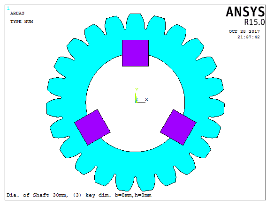
Each case contained three types of keys (parallel key (rectangular cross-section) and parallel key (square cross section) and parallel key (circular section) and one, two, three and four keys are used in each case to illustrated its effect on the stress distribution. The boundary conditions were loading Fx=100 N and Fy=50 N and the location of applied load is on Tip.
To understand the stress distribution patterns in spur gear teeth, various cases were investigated by changing systematically, the key shaft size, geometry, number and position. In this section are presented the summary of the analyzed configurations and their parameters and an in-depth discussion of the results for each case study.
Overview of Cases:
1. Gear Sizes:
A-Two modules were considered:
• Module 2 (m = 2): Pitch Circle Diameter (PCD) = 50 mm.
• Module 7 (m = 7): PCD = 350 mm.
B-The key dimensions for each gear (e.g., root diameter, outside diameter, and fillet radius) were adjusted accordingly.
2. Key Shaft Configurations:
• Shapes: Rectangular, square, and circular keys were evaluated.
• Number of Keys: Configurations with one, two, three, and four keys were analyzed to observe their effects on stress distribution.
• Key Sizes: Key width (B), height (h), and diameter (for circular keys) were varied within predefined ranges for each module.
3. Boundary Conditions:
• A point load of 4000 N was applied at the pitch circle as is normally expected in gear load bearing.
• The analyses were carried out using 2D plane elements (Plane182), while the contact between the gear teeth and the key shafts was modeled by target (TARGE169) and contact (CONTA172) elements.
4. Objective of the Study:
• To arrive at the right key geometric design, size and position that reduces stress concentration without compromising on the strength of the structure.
Structure of the Analysis:
Each case is examined in detail, focusing on:
• Stress distribution patterns for varying key configurations.
• The maximum equivalent stress (MES) values observed for each design.
• Comparative performance of different key shapes and numbers.
The following sections detail the findings for each configuration.
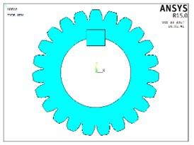
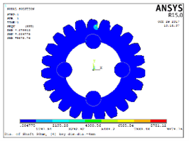
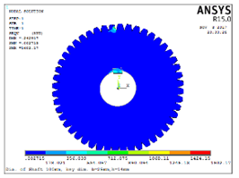
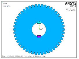
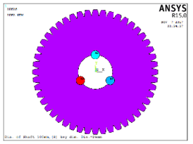
A finite element model with of teeth with (m = 2 and m = 7) is considered for analysis. A point load of 4000 N is applied at the pitch diameter then meshed with two-dimensional element (Plane182). The following steps are used for plotting the geometry of the gear tooth:
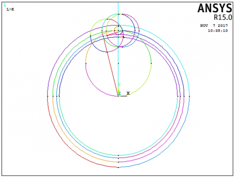
Divide the pitch circle, draw the root circle and draw the outside circle, draw a vertical line from the center of the circles to a point outside the circles. Illustrate the pressure line, the pressure line is drawn through the pitch point having an angle of 20 degrees from a line tangent to the pitch circle’s top, and then draw a line that divides the circular thickness angle. This line may either intersect or extend beyond the outside circle and then, locating the tooth form circle, draw circle (A) whose radius is 1/8 of the pitch diameter, with the pitch point as the center. Take another circle with the same radius as the first and the center at the vertex of circle (A) and the base one, this circle will build the top right curve of the gear tooth. Eliminate circle (A) and crop it to precisely the tooth shape, an arc that starts in pitch point and ends on the outside circle. Erase the initial round circle after you have already shaped the tooth form. Then, erase all the lines except for the circular thickness bisector, the tooth lines, and the initial round circle. Duplicate the form of molar or premolar with the central elongation line. Figure 1 is shown the steps above.
(a)
(b)
(c)
(d)
Figure 1. Steps of drawing gear tooth (a) Initial construction, (b) Layout design, (c) Tooth profile formation, (d) Final tooth design
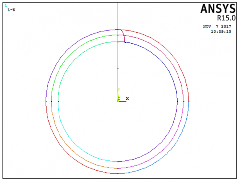
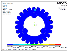
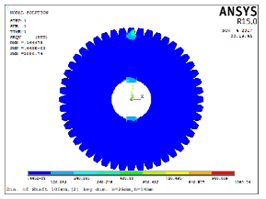
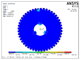
After that, the gear is meshed by element Plane182, the boundary condition is applied using pilot node in the gear center, which contact the shaft circle. Key is contact with the gear using Element targe169 and conta172 with MPC algorithm. Figure 2 illustrated the mesh and boundary condition of the gear [12].
The material properties used in the FE model are:
Materials: Steel (carbon steels C45). Standard Material Properties: Young's Modulus (E): 200 GPa. Poisson’s Ratio (ν): 0.28. Density (ρ): 7850 kg/m³. Yield Strength: (250–600 MPa). Ultimate Tensile Strength (UTS): (500–900 MPa).
Meshing process is essentially an important phase in FEA model since it disjoints the geometry into small elements to mimic the behavior of the analyzed structural entity. Mesh density plays crucial role in attaining a high-quality representation stress gradient, while element type is very crucial for the successful simulation. Solids elements are deployed for modeling gear teeth and key shafts contact elements being utilized for interaction points. Mesh quality is a decisive factor for attaining realistic results, and for that purpose well-formed elements are needed and for the distortion to be at the minimum. Boundary conditions serve as a connection between the simulated model and its actual environment. They are important for the accurate replication of stress distributions, so should be appropriately encoded to represent real world restrictions. The different visualisation tools of FEA software can help engineers look over the screens and detect any issues or mesh irregularities, which need to be taken care of before the analysis, can be carried out. Possibility of reproducing the numerical results is provided by the documentation as well as very important for validation of FEA. The documentation is an integral part of the analysis framework giving a full spectrum of the analysis setup. The teeth in the torque mesh, as in the spur gear, represent an important role for the overall accuracy of the results and the reliability of FEA results. This, in turn, helps engineers make better design choices and put more effort into optimization efforts, see Figure 2.
Figure 2. Mesh of the spur gear tooth with keys
Gears are most frequently used for transferring the power. They build up high stress concentration and this is at the root and point of contact. The repetitive fatigue of gear tooth, which results from the bending stressing on the fillets, is the primary cause of failure in the gear system. If failure in a gear results in a tensile fatigue, the consequences are irreversible and may take place without any preliminary indicators, so this work is of practical use for all the aforementioned reasons. Equipment design had been improved by the use of material improvement, by hardening surfaces with heat treatment and carburization, and by shot peening to improve the surface finish, etc. but less efforts have been made to improve strength and durability through the change of pressure angle, asymmetric teeth geometry alteration, root fillet curve geometry alteration, and so on. The majority of those methods are not the ones, which could give the comfort of the regular gear changes. The effect and use of stress relief feature in geometry of gear is studied by using different size of key with different location.
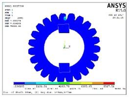
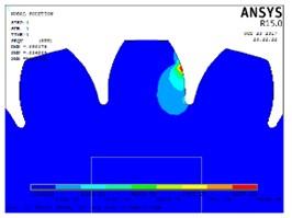
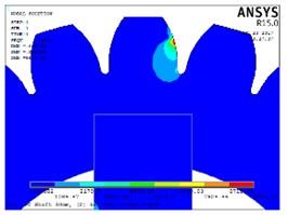
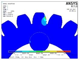
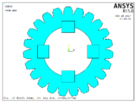
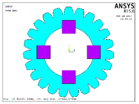
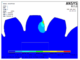
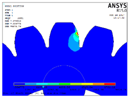
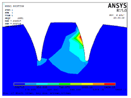
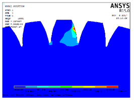
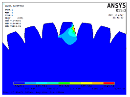
Application of stress relief features of different sizes of key and at same location (with rectangular, square and circular key) and with different number (one, two, three, and four keys) are shown in the following Tables 2-5 with module = 2 and Tables 6-9 with module = 7.
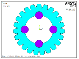
For Tables 2-5, pitch circle diameter = 50 mm, outside diameter = 54 mm, root diameter = 45 mm, center diameter = 47 mm, fillet = 0.4 mm, thickness = 3.14 mm.
For Case-1-, when B = 8 mm and h = 7 mm, the maximum equivalent stress (MES) is 9635 MPa. In addition, when B = 8 mm and h = 8 mm, the MES is 10081 MPa. Also, when the diameter of key = 8 mm, the MES is 9303 MPa.
For Case-2-, when B = 8 mm and h = 7 mm, the MES is 9593 MPa. In addition, when B = 8 mm and h = 8 mm, the MES is 9808 MPa. Also, when the diameter of key = 8 mm, the MES is 10004 MPa.
For Case-3-, when B = 8 mm and h = 7 mm, the MES is 9956 MPa. In addition, when B = 8 mm and h = 8 mm, the MES is 9391 MPa. Also, when the diameter of key = 8 mm, the MES is 9913 MPa.
For Case-4-, when B = 8 mm and h = 7 mm, the MES is 9874 MPa. In addition, when B = 8 mm and h = 8 mm, the MES is 10233 MPa. Also, when the diameter of key = 8 mm, the MES is 9878 MPa.
Table 2. One key with module = 2
|
Case-1- |
|||
|
B = 8 mm, h = 7 mm |
B = 8 mm, h = 8 mm |
Dia. of key = 8 mm |
|
|
Equivalent stress distribution (MPa) |
|||
|
Equivalent stress distribution (MPa) |
|||
|
Max. Eqv. Stress (MPa) |
9635 |
10081 |
9303 |
Table 3. Two keys with module = 2
|
Case-2- |
|||
|
B = 8 mm, h = 7 mm |
B = 8 mm, h = 8 mm |
Dia. of key = 8 mm |
|
|
Equivalent stress distribution (MPa) |
|||
|
Equivalent stress distribution (MPa) |
|||
|
Max. Eqv. Stress (MPa) |
9593 |
9808 |
10004 |
Table 4. Three keys with module = 2
|
Case-3- |
|||
|
B = 8 mm, h = 7 mm |
B = 8 mm, h = 8 mm |
Dia. of key = 8 mm |
|
|
Equivalent stress distribution (MPa) |
|||
|
Equivalent stress distribution (MPa) |
|||
|
Max. Eqv. Stress (MPa) |
9956 |
9391 |
9913 |
Table 5. Four keys with module = 2
|
Case-4- |
|||
|
B = 8 mm, h = 7 mm |
B = 8 mm, h = 8 mm |
Dia. of key = 8 mm |
|
|
Equivalent stress distribution (MPa) |
|||
|
Equivalent stress distribution (MPa) |
|||
|
Max. Eqv. Stress (MPa) |
9874 |
10233 |
9878 |
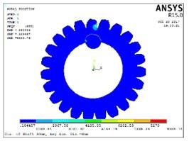
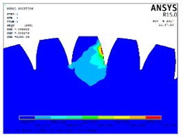
This part of the study is dedicated to the analysis using Finite Elements Method (FEM) that shows the effects of key shaft's size and position on the teeth stress relief in a spur gear. The results are then presented with an emphasis on how the different parameter of the key shafts affect the stress distribution and the implication of this for gear design optimization. The paper examined the stresses distribution of the spur tooth gear with the key at transverse plane at critical dimensions, i.e., pitch circle diameter, outside diameter, root diameter, center diameter, fillet radius and thickness. FEA software was applied for developing a 3D model and meshing the gear tooth, displaying the stress changes in different parts of the tooth. Most severe stresses were usually encountered under the tooth fillet, at the contact areas or the junction of the two members. The fillet radius had a prominent part in the stress distribution pattern, ensuing stress concentration in the tooth root reduction. A larger radius fillet will often lead to stress concentration reduction because it spreads the load more evenly between the gear tooth and the keyway. Tooth thickness is also in the same league with stress levels, as thin teeth are subjected to greater stress since they have less cross-sectional area. Optimized strategies are achievable after the equivalent stress distribution results are done. The strategies are meant to improve not just performance but also the longevity of the gear tooth. This may involve refining the fillet design, adjusting tooth thickness, or optimizing key shaft parameters to reduce stress concentrations and enhance overall gear durability. Comparing the results with industry standards and guidelines is essential for compliance with safety and reliability requirements. Deviations from recommended stress limits can prompt design modifications or additional stress-relief measures to achieve desired performance levels.
4.1 Stress distribution analysis
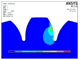
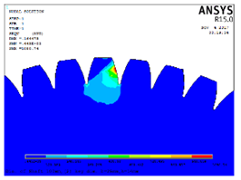
An analysis showed that key shaft stress distribution in gear teeth was different for various key shaft configurations. Increased stresses are found mainly at the point of the gear teeth where they are highly loaded, especially near the root and the tooth fillet area. Such alterations in the size and position of the main shaft incidentally affect the level of the stress on the tooth of the gear by creating some conditions in which the stress concentration is avoided.
(a) Rectangular key
(b) Square key
(c) Circular key
Figure 3. Equivalent stress in the tooth vs no. of key shaft with module = 2
The parametric study clearly shows that optimum shaft size, position (location), and stress distribution have to be traded off. Different designs corresponding to certain key shaft parameters often lead to a more homogeneous stress distribution and output to good gear performance. Designers will have to develop creative solutions by balancing stress relief objectives and practical aspects, which include space limitations, manufacturing practicality, and costing.
Figure 3 examines the impact of the number of key shafts on the equivalent stress distribution in the gear tooth. The results show variations in stress levels across the tooth profile, with the number of key shafts influencing stress distribution patterns. The analysis highlights the importance of optimizing the number and arrangement of key shafts to minimize stress concentrations and enhance gear performance. However, increasing the number of key shafts may add complexity and manufacturing cost to the gear assembly. Engineers must consider practical constraints such as space limitations, assembly requirements, and cost-effectiveness when deciding on the number of key shafts.
4.2 Effect of key shaft size
The key part, which is, increasing the diameter of the key shaft, is likely to result in the reduction of stress levels among gear teeth. The bigger key shape diameters transmit the pressure evenly over the contact surfaces between the teeth that helps to decrease pressure concentration. While it is possible that too big the shafts can result in weight and manufacturing complications without appreciable stress relief, the larger diameter may also contribute to the equalization of the stress. Based on the analysis by the FEA and the parametric studies, the following design revisions are proposed. Choosing a key shaft diameter to be right for the gear assembly and placing it properly to resist stress can prevent stress concentrations and strengthen gear life and endurance. In the context of simulation-based design, the repeated fine tuning of the shaft's parameters, such as its cross section and position, through successive iterative design steps can result in the best possible gear arrangement.
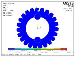
For Table 6-9, pitch circle diameter = 350 mm, outside diameter= 364 mm, root diameter = 328.89 mm, center diameter = 332.5 mm, fillet = 1.4 mm, thickness = 10.99 mm.
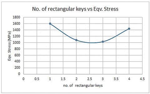
For Case-1-, when B = 25 mm and h = 14 mm, the MES is 1602 MPa. In addition, when B = 25 mm and h = 25 mm, the MES is 1967 MPa. Also, when the diameter of key = 25 mm, the MES is 1286 MPa.
For Case-2-, when B = 25 mm and h = 14 mm, the MES is 1080 MPa. In addition, when B = 25 mm and h = 25 mm, the MES is 1307 MPa. Also, when the diameter of key = 25 mm, the MES is 1279 MPa.
For Case-3-, when B = 25 mm and h = 14 mm, the MES is 1030 MPa. In addition, when B = 25 mm and h = 25 mm, the MES is 1169 MPa. Also, when the diameter of key = 25 mm, the MES is 1469 MPa.
For Case-4-, when B = 25 mm and h = 14 mm, the MES is 1445 MPa. In addition, when B = 25 mm and h = 25 mm, the MES is 1503 MPa. Also, when the diameter of key = 25 mm, the MES is 1190 MPa.
Table 6. One key with module = 7
|
Case-1- |
|||
|
B = 25 mm, h = 14 mm |
B = 25 mm, h = 25 mm |
Dia. of key = 25 mm |
|
|
Equivalent stress distribution (MPa) |
|||
|
Equivalent stress distribution (MPa) |
|||
|
Max. Eqv. Stress (MPa) |
1602 |
1967 |
1286 |
Table 7. Two keys with module = 7
|
Case-2- |
|||
|
B = 25 mm, h = 14 mm |
B = 25 mm, h = 25 mm |
Dia. of key = 25 mm |
|
|
Equivalent stress distribution (MPa) |
|||
|
Equivalent stress distribution (MPa) |
|||
|
Max. Eqv. Stress (MPa) |
1080 |
1307 |
1279 |
Table 8. Three key with module = 7
|
Case-3- |
|||
|
B = 25 mm, h = 14 mm |
B = 25 mm, h = 25 mm |
Dia. of key = 25 mm |
|
|
Equivalent stress distribution (MPa) |
|||
|
Equivalent stress distribution (MPa) |
|||
|
Max. Eqv. Stress (MPa) |
1030 |
1169 |
1469 |
Table 9. Four keys with module = 7
|
Case-4- |
|||
|
B = 25 mm, h = 14 mm |
B = 25 mm, h = 25 mm |
Dia. of key = 25 mm |
|
|
Equivalent stress distribution (MPa) |
|||
|
Equivalent stress distribution (MPa) |
|||
|
Max. Eqv. Stress (MPa) |
1445 |
1503 |
1190 |
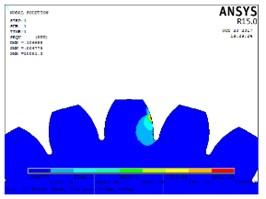
4.3 Effect of key shaft location
The provision of a key shaft in the opposite side of gear teeth leads to complicated stress modification. The critical shaft is being moved nearer the tooth tip which can perhaps lead to less stresses around fillet regions but it could increase the stresses at other areas. The optimum key shaft position is likely to be dependent on different factors such as tooth geometries, and loading conditions and material properties.
The study compares the equivalent stress in the gear tooth for different key shafts (rectangular, square, and circular) to understand how their geometry affects stress distribution. The analysis emphasizes the importance of selecting the optimal key shaft geometry to minimize stress concentrations and enhance gear performance. Rectangular key shafts may induce stress concentrations at the corners, resulting in localized high stress regions. Square key shafts provide a more uniform distribution of stress, but the contact area between the square shaft and gear tooth may be smaller. Circular key shafts offer a smooth contact interface with the gear tooth, minimizing stress concentrations and distributing load more evenly.
(a) Rectangular key
(b) Square key
(c) Circular key
Figure 4. Equivalent stress in the tooth with no. of key shaft with module = 7
The current FEA model and analysis have the following drawbacks: assumed material properties, boundary conditions, no dynamic analysis, geometrical and mesh approximations, single material consideration, and no experimental verification. The FEA disregards geometrical non-linear effects, which may be manifested in beams at high stresses, where they can exhibit non-linear behaviour, plastic deformation or strain hardening. This could lead to underestimation of stress concentrations and inability to predict other possible failure modes that might occur at service conditions. The boundary conditions that are employed in FEA do not necessarily mirror real life boundary condition, and therefore the stress distribution that is predicted is not entirely accurate needed in order to make key shaft configuration recommendations that are reliable. It also does not take into account realities of manufacturing such as defects in geometry such as may be seen in tooth profiles of gears and key shafts. This may lower the reliability of calculated stress distribution that in turn could lead to overstressing the degree of stress relief by a particular design modification. One major drawback of the study is the specific focus exercised which makes it difficult to use the research results for other materials or purposes. Lastly, the failure to conduct experiments to arrive at the conclusions presented by the authors will cause certain design optimizations to be questioned, as shown in Figure 4.
Finally, this article can be summarized as stress reduction via the stress alleviator feature is achievable. The stress redistribution is quite sensitive to the change in sizes, Locations and the Number of piles, thus select size, Locations and the Number very carefully. Incorporating a single circular key as a source of stress relief means individuals will have more stress reduction with m = 2 and double circular key within m = 7. Small tolerance in length, place, and amount can bring about a big difference in the equivalent stress. Stress reliving feature must be introduced considering the location, size and number of places in order to obtain maximum reliving of stress or it may be the case that strength of gear reduces.
The FEA study, therefore, incorporates very useful knowledge concerning the stress relief of the spur gear teeth through the changing of the key shaft size and position of the shaft itself. This makes it possible to FEA invent any gear design to decrease the load, increase the performance and prolong the life of the gear systems. It is also pertinent that more research is sought for in order to perfect the design principles and tools, to validate the simulation outputs, and to boost the innovation level of the gear technology.
It is worthwhile to be conscious of the imperfections of the FEA study that include material behavior simplifications, boundary conditions, as well as loading assumptions. While future research may consider the contemporary methods, such as nonlinear material behavior, contact analysis, and fatigue life prediction as an advanced modeling technique that helps refine stress predictions' accuracy. It is advisable to carry out the validation of FEA results experimentally to validate the design optimization of proposed remodeling and ensure it is workable on ground.
For pitch circle diameter = 350 mm, outside diameter= 364 mm, root diameter = 328.89 mm, center diameter = 332.5 mm, fillet = 1.4 mm, thickness = 10.99 mm and for Case-1-, when B = 25 mm and h = 14 mm, the MES is 1602 MPa. In addition, when B = 25 mm and h = 25 mm, the MES is 1967 MPa. Also, when the diameter of key = 25 mm, the MES is 1286 MPa. For Case-2-, when B = 25 mm and h = 14 mm, the MES is 1080 MPa. In addition, when B = 25 mm and h = 25 mm, the MES is 1307 MPa. Also, when the diameter of key = 25 mm, the MES is 1279 MPa. For Case-3-, when B = 25 mm and h = 14 mm, the MES is 1030 MPa. In addition, when B = 25 mm and h = 25 mm, the MES is 1169 MPa. Also, when the diameter of key = 25 mm, the MES is 1469 MPa. For Case-4-, when B = 25 mm and h = 14 mm, the MES is 1445 MPa. In addition, when B = 25 mm and h = 25 mm, the MES is 1503 MPa. Also, when the diameter of key = 25 mm, the MES is 1190 MPa.
The study also shows that circular keys are the most effective in stress relieve because they do not have sharp corners whereby pressure is concentrated. Among the two types of designs, rectangular and square types of keys exert greater stress concentrations. The results also show that the size of the module influences stress relief, and for a single circular key the stress was relieved with an MES of 9303 MPa. The use of double circular keys results to best stress relieving when placed and sized as indicated with an MES of 1279 MPa. A greater key size decreases stress, but where the key sizes are significantly large, there are issues with manufacturing and assembling. In the practical design, the arrangement of the keys helps to minimize stress concentrations at the tooth root and fillet sections. Stress distribution improves when more keys are added this is however likely to reduce as the complexity and cost increase as the number of keys added increases and it is advisable to have a maximum of two keys.
Stress reversal in gears depends on geometry, size, position and number of keys. Circular keys in general and single or double circular key arrangement in particular always ease pressure. It is essential to provide the balance between the stress relief and those practical features, such as manufacturability, cost, and assembly. For the smaller modules, one circular key is suggested, while the larger modules are suggested to be accommodated with two circular keys. Reduced-stress features should be integrated in a manner that such enhancements offer better reliability without compromising the reliability of the system and avoids complicating the design.
[1] Dhavale A.S., Utpat, A. (2013). Study of stress relief features at root of teeth of spur gear. International Journal of Engineering Research and Applications (IJERA), 3(3): 895-899.
[2] Prajapati, J.M., PA, V. (2013). Factor affecting the bending stress at critical section of asymmetric spur gear. International Journal of Mechanical Engineering and Technology (IJMET), 4(4): 266-273.
[3] Singh, V., Chauhan, S., Pali, H.S. (2013). ISTE146 Stress analysis of a spur gear tooth using solidworks and stress reduction by stress relief hole. In ISTE Delhi Section Convention on “Technological Universities and Institutions in New Knowledge Age: Future Perspectives and Action Plan”, Delhi Technological University. https://www.researchgate.net/publication/270554796.
[4] Ambade, V.V., Vanalkar, A.V., Gajbhiye, P.R. (2013). FEM analysis of spur gear tooth. International Journal of Engineering Research and Applications (IJERA), 3(4): 2210-2216. https://www.researchgate.net/publication/361436921.
[5] Karaveer, V., Mogrekar, A., Joseph, T.P.R. (2013). Modeling and finite element analysis of spur gear. International Journal of Current Engineering and Technology, 3(5): 2104-2107.
[6] Rathore, R.K., Tiwari, A. (2014). Bending stress analysis & optimization of spur gear. International Journal of Engineering Research, 3(5): 2044-2049.
[7] Badithe, M., Srikanth, S., Bodapall, J. (2014). Stress and reduction analysis of a spur gear tooth. International Journal of Emerging Technology and Advanced Engineering, 4(3): 760-768.
[8] Reddy, M.P., Santhosh, M. (2015). Spur gear tooth stress analysis and stress reduction using stress reducing geometrical features. International Journal of Mechanical Engineering and Technology, 6(9): 17-29. https://iaeme.com/MasterAdmin/Journal_uploads/IJMET/VOLUME_6_ISSUE_9/IJMET_06_09_003.pdf.
[9] Jammal, A., Wang, H., Rong, Y. (2015). Spur gears static and dynamic meshing simulation and tooth stress calculation. MATEC Web of Conferences, 26: 03001. https://doi.org/10.1051/matecconf/20152603001
[10] Amani, A. (2016). Computationally efficient analysis & design of optimally compact gear pairs and assessment of gear compliance. Doctoral dissertation, Delft University of Technology. https://doi.org/10.4233/uuid:9b46e18b-1fa3-4517-a666-660e4a50f18e
[11] Singh, G. (2017). Finite element analysis of spur gear. Doctoral dissertation, University of Technology.
[12] Bekheet, N. (2017). Involute gear tooth stresses analysis using finite element modeling. Journal for Engineering, Technology, and Sciences, 34(1): 269-284.
[13] Patil, N.U., Chaphalkar, S.P., Chaudhari, G.L. (2017). Stress analysis of spur gear by using different materials a review. International Conference on Ideas, Impact and Innovation in Mechanical Engineering, 5(6): 355-363.
[14] Prabhakaran, S., Balaji, D.S., Kumar, R.P. (2017). Bending stress analysis of a spur gear for material steel 15Ni2Cr1Mo28. Journal of Engineering and Applied Sciences, 12(19): 5636-5641.
[15] Muminovic, A.J., Colic, M., Mesic, E., Saric, I. (2020). Innovative design of spur gear tooth with infill structure. Bulletin of the Polish Academy of Sciences: Technical Sciences, 68(3): 477-483. https://doi.org/10.24425/bpasts.2020.133370
[16] Vigneshwaran, K., Shanmugam, D., Balasuthagar, C. (2020). Experimental and analytical stress analysis of spur gear. IOP Conference Series: Materials Science and Engineering, 912(2): 022043. https://doi.org/10.1088/1757-899X/912/2/022043
[17] Güven, F. (2021). Effect of design parameters on stresses occurring at the tooth root in a spur gear pressed on a shaft. Proceedings of the Institution of Mechanical Engineers, Part E: Journal of Process Mechanical Engineering, 235(4): 1164-1174. https://doi.org/10.1177/0954408921995292
[18] Rocha, L.M.L., Alves, M.T.S. (2021). Finite element analysis of a spur gear considering mass relief strategies. VETOR-Revista de Ciências Exatas e Engenharias, 31(2): 36-49. https://doi.org/10.14295/vetor.v31i2.13710
[19] Mohammed, J., Ramadan, D. (2022). Numerical and theoretical analysis of a spur gear using composite and conventional materials. Engineering and Technology Journal, 40(7): 996-1005. https://doi.org/10.30684/etj.2022.133641.1198
[20] Ahmed, B.A. (2022). Optimization of fatigue life in laminated composite plates. Curved and Layered Structures, 9(1): 425-441. https://doi.org/10.15587/1729-4061.2022.266261
[21] Ahmed, B.A. (2022). Identifying the influence of dimensional parameters on the stresses and deformations of two helical gears. Eastern-European Journal of Enterprise Technologies, 5(7(119)): 76-83. https://doi.org/10.15587/1729-4061.2022.266261
[22] Yılmaz, T., Karadere, G., Karpat, F. (2023). A numerical investigation on the stress-balanced spur gear pairs. Uludağ Üniversitesi Mühendislik Fakültesi Dergisi, 28(1): 1-10. https://doi.org/10.17482/uumfd.1174526
[23] Hassan, A.R., Hawas, M.N., Abdullah, A.R., Majdi, H.S., Habeeb, L.J. (2023). High-speed helical gear design parameters effect on the dynamic stress. Mathematical Modelling of Engineering Problems, 10(4): 1189-1198. https://doi.org/10.18280/mmep.100411
[24] Shams, O.A., Ahmed, B.A., Majdi, H.S. (2023). Comparative analysis of aluminum alloys 2024 and 7085 under thermal fatigue and crack propagation. International Journal of Heat and Technology, 41(4): 929-936. https://doi.org/10.18280/ijht.410415