Ali M. Abdulrahman*![]() | Serdar Ay
| Serdar Ay![]()
© 2025 The authors. This article is published by IIETA and is licensed under the CC BY 4.0 license (http://creativecommons.org/licenses/by/4.0/).
OPEN ACCESS
Robotic welding processes have been widely utilized in a variety of manufacturing applications such as shipbuilding, oil and aerospace since the early 1960s in order to establish strong and high-quality joints between metal components rapidly. Therefore, this study focuses on the topology optimization of KUKA KR 16 in order to enhance maneuverability and reduce the initial and operational costs. The remodeling of the KUKA KR 16 is executed through a meticulous process in SolidWorks. The design details of the KUKA KR 16 are determined based on the specified operational range, as indicated by the data provided by the manufacturer’s data. A significant reduction in the weight of the KUKA KR 16 is achieved through the optimization process, while the performance metrics are maintained or even improved. Based on the obtained results, it can be concluded that the employed topology optimization approach effectively reduces the weight of the KUKA KR 16 without compromising its performance. Improved structural efficiency is demonstrated by the optimized design, potentially resulting in benefits such as energy savings, increased payload capacity, or enhanced maneuverability. In conclusion, this study presents a lighter and low-cost robotic arm by decreasing the weight of the upper arm of the KUKA KR 16 by 40%, which results in a reduction of the total arm weight. It leads to a total reduction of more than 9.745% of the robotic arm to reach a weight of 212.098 kg overall following the optimization process.
welding robot, KUKA KR 16, computer-aided design (CAD), topology optimization, size optimization, shape optimization
Robotic arms are auto manipulators that have been designed to perform tasks that a human arm can perform. Manipulator's sections are connected by joints that allow for either translational (linear) or rotational (as in a jointed robot) movement. One of the most important manufacturing uses of robotic arms is arc welding [1].
In addition to that, and of greater significance, the weight of the device has been reduced in general by this mechanism. As is widely acknowledged, a decrease in weight is intended to result in a reduction in cost. Consequently, a considerable number of KUKA KR16 equipment units have been facilitated to be purchased, to diminish the employed in the hazardous environment [2].
Research and development (R&D) efforts are made by researchers to design and develop novel methods and useful techniques that can be used and implemented widely in this sector to help alleviate all these obstacles, barriers, and challenges associated with the welding process in automobiles that may impose difficult working conditions for employees.
One of these inventive solutions and practical methods is the robotic welder. Robotic welding is a typical application of modern technology in dangerous settings to protect workers from exposure to poisonous gases and high temperatures. However, to enable the production of high-performance cars that are comparable in their dependability, efficiency, and accuracy, car manufacturing managers should carefully address and take into account several important factors, including performance, accuracy, and the amount of welding material used for each vehicle [3]. Also, employing those cutting-edge welding robotic arms is useful for accessing hard-to-reach areas in the car body and conducting the welding method with greater degrees of speed and precision compared to human workers [4].
The widespread use of robotic welding also necessitates a greater capacity for controlling welding settings, robotic mobility, and improved defect exploration and repair. The key challenges are joint detection, weld permeation control, and joint width measurement. As a result, upgrading a robot system is still a challenging endeavor. Such a challenge is a serious attempt to improve arc robot welding by employing a cutting-edge solution like numerical simulation to address these issues that cause difficulties when using arc robot welding [5, 6].
The heightened production rates, coupled with the shortage of skilled labor in small industries, have led to an increasing reliance on industrial automation, particularly robotic arms, for efficient material handling and sorting. The key innovation is being found in the strategic utilization of to change the type of metal and work to reduce its weight for the robotic arm. The reduction in weight is a pivotal aspect in catering to the compact sizing, high strength, and lower payload requirements that are characteristic of small industries. The cost-effectiveness of robotic arm manufacturing is influenced by the transformative impact of weight reduction and material change. The challenges faced by small manufacturing industries are being addressed by the design, and avenues for enhanced automation in regions grappling with similar constraints are being opened [7].
From the conclusions reached by researchers in the field of robot development within the applications of mechanics, based on the earlier studies in which they are identified, it is noted that arc welding has been intensively studied for additive manufacturing of big metal components due to its affordability, adaptability in build size, and high deposition rates. The utilization of the KUKA KR 16 robotic arm in welding processes is widely recognized within the manufacturing industry. The selection of the KUKA KR 16 is grounded in its distinctive attributes, encompassing precision, adaptability, and efficiency, positioning it as a pivotal tool in welding applications across diverse sectors. The key contributing factor to the widespread adoption of the KUKA KR 16 in welding operations is its versatility. Programmable to execute various welding tasks, including spot welding, arc welding, and seam welding, the robotic arm exhibits flexibility that aligns with the multifaceted requirements of welding processes in different industries. The integration of the KUKA KR 16 robotic arm also engenders enhancements in productivity. The robot's capability to operate continuously without succumbing to fatigue results in accelerated production cycles and reduced manufacturing durations. Moreover, in certain applications, there is an emerging need for human-robot collaboration in welding operations. The imperative of ensuring the safety of human workers while incorporating robotic arms, such as the KUKA KR 16, into the welding process represents a significant challenge necessitating meticulous consideration and the implementation of safety protocols. In conclusion, notwithstanding the significant advantages offered by the KUKA KR 16 robotic arm in welding applications, the resolution of the aforementioned challenges is imperative for optimizing its effectiveness within the dynamic landscape of the welding industry. The goal of the previous project was to create a completely automated system for the additive production of metal components using robotic gas metal arc welding. With merely a CAD model as input; the study shows how to automatically fabricate a thin-walled aluminum structure. This achievement shows how far we come towards developing a workable, highly automated additive manufacturing system based on arc welding that is appropriate for industrial applications [8].
As explained in the case study, friction stir welding (FSW) is used to successfully attach an AA6082 reinforcement into a high-pressure die-casted cylinder block. The above-stated project shows that FSW can combine very complex geometries with temperature feedback control. Only a few trial welds are made when establishing the weld method, saving time and money. It also highlights the possibility of constructing complex welded structures consisting of several cast and wrought alloys at low cost and excellent quality [9].
It does a topological optimization of the KUKA 16 type forearm upper robotic arm. For the purpose of ensuring the study's realism, the model is subjected to dynamic situations that are within its operational range, and boundary conditions as for such joint forces and torques can be measured [10].
The study investigates robotic arm kinds, needs, research scope, industrial scenario, and limits. The study examines MBI and significant architecture design of journal industry updates [11]. It constructs a welding line image processing method by watching sheet margins moving at the desired pace with a three-degree robot arm. This improves the method created and analyzed edge detection and top-hat transmutation algorithms. ANFIS fuzzy logic optimizes robot movement, and MIG welding boosts performance. System components work by making welding path monitoring reliable [12]. According to such study, the conceptualization, design, refinement, and installation of an integrated robot welding system, which produces complementary automated multi-line welding for V-groove geometries with single sides, are based on a ground-breaking cost-function concept with immediate impacts on direct automated robotic welding costs. A multi-pass welding system integrated enables the automatic sequence and adaptive development of the welding schedule and allocation of welding parameters. By reducing human input and removing programming overhead between jobs, the system's flexibility is boosted [13].
Industrial robots are widely used in manufacturing operations, according to which these self-driving, programmable robots, which typically have six or more axes, are now available. inspection. While preserving strict laser welding requirements, manufacturers work to increase production efficiency. The application software can be enhanced further by adding data logging features, real-time route correction values, and calibration parameter tweaks [14]. In the last mentioned study, robot paths and welding paths are improved to obtain the shortest trajectory distance and a collision-free path. The suggested algorithm is compared to three conventional algorithms, and the results show how good the suggested approach is. The recommended method is applied to improve the trajectory of an actual arc welding robot, and the desired optimized results are obtained. As a result, engineers can utilize the provided method to assist in constructing the arc welding robot trajectory [15]. The "Kunshan No. 1" welding robot control software is used to construct a visual acquisition method and assesses the positioning accuracy of the welding robot. The contributing factors and optimal system setup settings can be found by creating a visual calculation error analysis model. The inverse kinematics issue is numerically solved by using the differential definition of the Jacobian matrix. The objective of soldering seam monitoring is accomplished along with MATLAB [16].
The aim of this study is to remodel an existing robot named KUKA KR16 industrial robot in order to obtain lighter, lower-cost, and better perform modified robot by using SolidWorks. Numerical analysis and mathematical modeling are then carried out using FEA principles via the ANSYS software package, and some important factors that affect the performance and efficiency of the robotic arm used in the welding of automobiles are identified.
The main steps of this study are summarized as follows:
1) Creating a process to use SolidWorks to enhance the KUKA robotic arm's shape for a better appearance.
2) Using ANSYS software to simulate the KUKA robot arc welding model through 3D numerical modelling.
3) Calculating stresses, strains, and deformations to the model's component parts in order to evaluate the performance of the KUKA robot arc welding. This process will be carried out for each case study.
4) Applying ANSYS to carry out comparison studies on the outcomes of modifying the shape, and volume.
Moreover, the spread utilization of robotic welding requires more ability to domain welding parameters and robotic movement and enhanced defect exploration and repair. Hence, the robotic welding process may experience a set of problematic troubles. The most popular types of those problems are the demands to compensate for repair errors, trues for the work part, differences in work part sizes, and in-operation thermal deformations. The main difficulties are joint detection, weld permeation control, and measurement of the width of a joint. These issues are efficient with the utilization. Thus, improving a robot system is still a difficult task, and the study is a serious attempt to enhance arc robot welding using an advanced solution such as numerical simulation to deal with these factors that leads to challenges in using arc robot welding [6, 17].
In this study, a systematic approach is followed, with the utilization of software tools such as SolidWorks and ANSYS, as the integration of SolidWorks and ANSYS allows for a seamless workflow from design (SolidWorks) to analysis and simulation (ANSYS). Mechanical systems are understood, refined, and validated by engineers, thereby ensuring robust and efficient design the methodology is outlined in the following steps:
1) The upper arm of the Kuka KR 16 robot arm is the focus of the study. It is chosen precisely due to its high susceptibility to stresses and continuous exposure to movement. Additionally, the weight of the piece connected to the handle is borne by the third link. This link is being studied to be improved without reaching a state of failure.
2) The upper arm is made of alloy steel. Therefore, St 37 metal is formed as a result of its lightweight nature, ease of restructuring, and lower cost. St 37 is utilized for its advantages, with the most significant one being its lightweight and ease of formation. So far, no defects have been discovered on this side. However, as science is known to continue evolving, the conversion of the metal type from steel alloy to St 37 is currently being subjected to a thorough examination of possible defects. The formulation of a prudent plan is necessitated to effectively address these concerns. The mechanical properties are being discussed. A reduction in critical mechanical properties such as force, strength, and resistance to erosion may be caused by the change in the substance. The extent of these changes is determined by the steel alloy being replaced. The mechanical requirements of the intended application need to be thoroughly analyzed. If the necessary criteria are met, the applicability of the transformation can be considered, provided that the mechanical properties of St 37 are consistent. Instead, the necessity of considering the merging of adjustments or post-treatment treatments is emphasized to ensure that specific characteristics are.
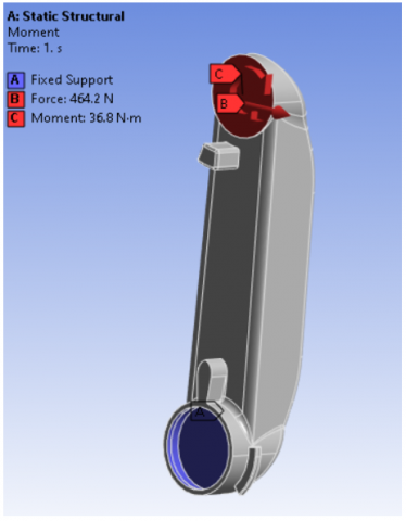
3) After that, the entire robot body with the exact dimensions is imported into ANSYS. The upper arm is analyzed via the ANSYS package in terms of some mechanical settings that are done by the ANSYS software. The mesh is set with an element size of 10 mm to ensure that accurate results are given by ANSYS. The boundary condition is set with an applied force of 464.2 N and a moment of 36.8 N.M.
4) During the simulation process, methods for optimizing topology, shape, and size are utilized. Various techniques are used to improve the dimensions and shape of the upper arm and reduce the weight. The primary focal points associated with the upper arm are enhanced productivity and reduced expenses. Several strategies that result in the increased or enhanced performance of metal structures can be implemented using ANSYS. Topology optimization is a technique that is frequently used in the engineering and design domains in order to optimize the configuration and arrangement of structures. The objective of the structural allocation method is to be optimized by the decrease in overall weight and the enhancement of the structural integrity of a given system through the strategic placement of metal components. The enhancement of strength and efficiency in a metal structure is significantly impacted by the optimization of component arrangement inside, which is a significant factor in metallic materials. The form optimization technique for the upper portion of the robot arm is involved in adjusting the fixed locations of the component while ensuring constant torque and force conditions. The shape and material distribution of a structure are maintained while modifying its dimensions, such as length or thickness, in a process known as size optimization. The effect on metals is that the size of metal components is refined to meet performance goals with less material. The differences are being examined. The examination of material placement is conducted in topology optimization. The outside shape is altered through the process of shape optimization while ensuring that the internal material remains unaltered.
5) The size is first optimized by reducing the thickness of a specific part of the upper part of the robot arm, and the part that is reduced using ANSYS is determined because it has the potential to study which places can be reduced in thickness without the reduction leading to a failure in the piece. A basic thickness dimension of 20 mm is adopted, and analytical studies are carried out about it. Then, the thickness is reduced by 5 mm, and then it is further reduced by 10 mm better results are obtained from any thickness that is looked at.
6) After that, the shape optimization of the upper part of the robot arm is carried out by altering the points at which the piece is secured while the same force and torque conditions are maintained.
7) After that, all cases are studied to find what point of fixation is given by the upper part of the robot being fixed. Better results are achieved. After that, the topology optimization of the upper part of the robot is done by removing unnecessary parts, and the piece does not fail after the removal. The removal is done in two cases: the first with a value of 20 percent of the size of the piece and the second with 40 percent of the weight of the piece, and it must be noted. The removal is done randomly, through the inspection program, to ensure that there is no failure in the piece and to obtain a lighter weight with a low cost and good performance. After three cases of improvement have been conducted, a comparison is made to determine which case is the best, and it is concluded that the improvement of the topology is the best because the optimization of topology has been enhanced. The achievement of optimizing material placement within the metal structure has been accomplished. The best way to distribute the useful material in the design space with the optimal solution is through topology optimization, which offers benefits such as lighter mass and cost-saving advantages in manufacturing. The structural performance under various material placements is analyzed by ANSYS using algorithms. Iterative simulations are conducted, wherein the adjustment of material distribution is performed until an optimal configuration is attained. The effectiveness is determined by considering criteria such as stress distribution, weight reduction, and structural integrity. Shape optimization is a process that involves the modification of a given shape to achieve optimal performance or desired characteristics. It is a widely studied topic in various fields. The device details of the following table can be seen from the specifications:
The device details of the Table 1 can be seen from the specifications:
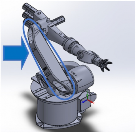
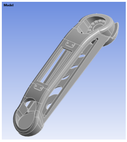
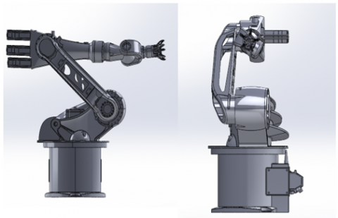
Figure 1 is represented by the robot used in the study, and the part being studied is specifically shown in the indicator part of the upper arm.
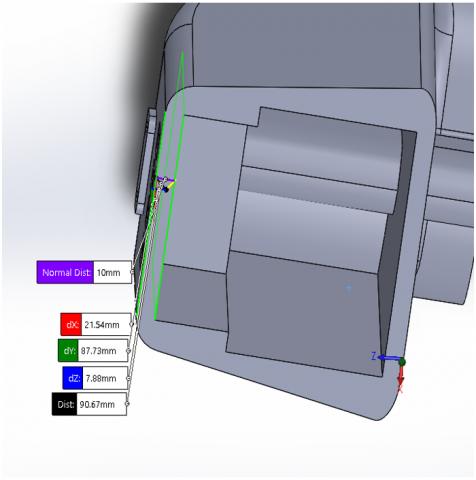
In Figure 2, the CAD model of the KUKA KR16 upper arm is presented, including front and back views.
Table 1. The KUKA KR 16 specifications [18]
|
Brand |
KUKA |
|
Model |
KR16 |
|
Type |
Robot Arm |
|
Axes |
6 |
|
Payload |
16 kg |
|
Reach |
1611 mm |
|
Repeatability |
0.05 mm |
|
Weight |
235 kg |
Figure 1. KUKA KR16 CAD model [19]
Figure 2. Front and back views of KUKA KR16 upper arm as a CAD model
In the table and previous figures, the measurements of the robot that has been adopted and images of the component that have been worked on are shown, along with the appearance of the robotic arm that has been adopted.
The fundamental techniques in engineering design, particularly in the context of enhancing the overall performance of a robot arm, are being discussed. Specific aspects of the design are addressed by each optimization method, thereby contributing to the enhancement of the functionality and efficiency of the robot arm. Size optimization is important as it allows for the adjustment of the dimensions of the robot arm, such as length or thickness. Through size optimization, the weight, dynamics, and overall structural integrity of the robot arm can be impacted.
The influence on performance is ensured by optimizing size, which allows the robot arm to meet performance goals with minimal material usage, resulting in a reduction of unnecessary weight and an enhancement of its agility and responsiveness. Shape optimization is being considered in this study is important to note that the modification of the external shape of the robot arm while ensuring the maintenance of force and torque conditions is deemed crucial for the streamlining of its aerodynamics, the reduction of stress concentrations, and the enhancement of its overall form.
In engineering and design, topology optimization is a technique that is used to optimize the form and arrangement of systems or structures. The significance of topology optimization is that the most effective material arrangement within the design space of the robot arm is prioritized. The arm's structural integrity is preserved and the most use is made of its weight by this method. The ideal locations for material placement in the robot arm are established by topology optimization, ensuring a balance between strength and weight. Overall performance and efficiency are raised by a more robust and lightweight structure. The combination of these optimization techniques leads to the development of a balanced strategy that enables the approach of robot arm design from a comprehensive perspective. Efficient material usage is ensured by size optimization, improved dynamics are achieved through the refinement of external geometry by shape optimization, and structural integrity is enhanced by topology optimization. On the one hand, enhanced efficiency is the collective impact of these optimization methods leads to the creation of a robot arm that is not only structurally sound but also characterized by increased energy efficiency, precision, and responsiveness in its movements. In summary, a comprehensive strategy to enhance the overall performance of a robot arm is provided by focusing on size, shape, and topology optimization methods. Various aspects of design, structural integrity, and operational efficiency are addressed by these methods.
By using boundary condition constants, such as force and torque, optimization of the upper arm of the KUKA KR16 robot is accomplished in this work. Three cases of optimization are looked at: size optimization to reduce thickness and adjust dimensions, shape optimization to produce more accurate results; and topology optimization to improve the robot arm's shape to lessen the weight of the upper arm, which is done with the ANSYS program.
3.1 Size optimization results
It is frequently used to identify the best options for the key product attributes, including material choice, section thickness, and a few other parts factors. For instance, designers may use form optimization to minimize the risk of failure of the component or product when pressure and force concentrations are high during analysis.
After decreasing the thickness from its initial value of 20 mm by 10 mm, the thickness is improved. The entire performance and characteristics of the thickness are then evaluated to determine the influence of this reduction in thickness.
The modified portion, which is reduced from the original thickness of 10 mm via the size optimization method, is represented in Figure 3.
The greatest stress and the maximum deformation are 0.021059 mm and 3.6557 MPa, respectively at the thickness of 10 mm shown in Figure 4.
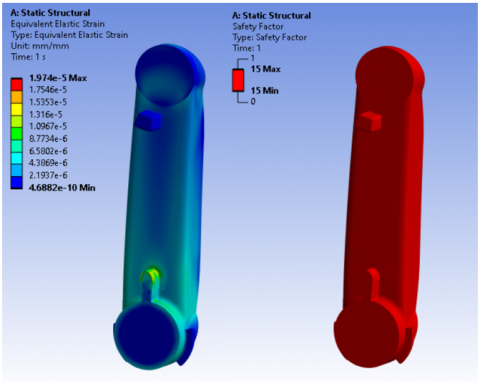
The elastic strain is calculated to be 0.00001974 mm/mm and the arm is safe at this thickness of 10 mm, when the safety factor is 15 or greater as shown in Figure 5.
Insights into the stress, deformation, safety factor, and elastic strain related to the thickness of 10 mm are provided by these results, which are acquired after the analysis is completed.
Figure 3. Cross section of the reduced thickness is 10 mm
Figure 4. Maximum von Mises stresses and total deformations of the robot’s upper arm
Figure 5. Safety factors and elastic strain of the robot’s upper arm
Figure 6. Boundary conditions on the shape
3.2 Shape optimization results
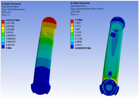
The simulation of the hexagonal shape takes into account the proper boundary conditions. The accompanying illustration shows a hexagonal shape with a fixed support. The hexagonal shape is chosen due to the well-documented aerodynamic efficiency of hexagonal shapes, which is recognized for its ability to minimize drag and potentially enhance the efficiency of the arm's movement and stress distribution. Enhanced structural integrity is achieved through the provision of a more uniform stress distribution, which is facilitated by the hexagonal shape. The improved aerodynamics are brought about by the hexagonal shape, resulting in reduced air resistance and contributing to smoother and more efficient movements, except for that positive impact. A more uniform stress distribution can be achieved to improve structural stability during operation. Cost savings can be achieved through the utilization of a compact hexagonal design, which requires less material. The potential for simpler manufacturing is observed when a simplified shape is considered, which may lead to cost reductions depending on the manufacturing process. In summary, the choice of a hexagonal shape in the Shape Optimization Results is justified based on its aerodynamic and stress distribution properties. The effects on performance, efficiency, and cost are nuanced and are dependent on the specific requirements and constraints of the robot arm's application. The practical implications of the shape change are confirmed through rigorous testing and validation. The strength and torque are shown to be unaffected. The conditions applied to the upper arm of the robot are represented in Figure 6.
The shape's maximum stress and deformations of the hexagonal shape are 0.019332 mm and 2.2 MPa respectively, as shown in Figure 7.
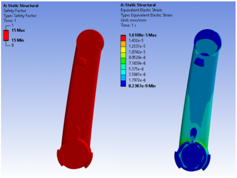
The safety factor is greater than 15, and this indicates that the arm is secure and the shape's maximum elastic strain is 0.000016108 mm/mm. Figure 8 shows the hexagonal shape and its maximum strain.
Figure 7. Maximum von Mises stresses and total deformations of the robot’s upper arm
Figure 8. The safety factors and elastic strain of the robot's upper arm
3.3 Topology optimization results
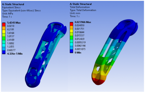
The best way to distribute useful material in the design space is through the utilization of the topology optimization method. The removal of unnecessary densities is allowed. The mass is reduced, and the industrial manipulator components are made more energy efficient by this approach. Simultaneously, the stiffness of the robotic components is maximized, and dynamic performance and stability are enhanced. A 40% mass reduction in the robot's upper arm is achieved through topology optimization. The results of topology optimization are obtained through the analysis of the structural performance of the upper arm using ANSYS software, and areas that can be deemed as "unnecessary" are identified based on predefined criteria. Sophisticated algorithms and finite element analysis (FEA) are utilized by the software to simulate various material distributions, with the impact on structural integrity and overall performance being iteratively assessed. Candidates for removal or reduction can be identified as parts of the upper arm that contribute less to load bearing or experience lower stress levels, ultimately leading to the optimization of the arm's topology. The significant and multifaceted implications of a 40% mass reduction on the robot arm are being considered. Improved agility, responsiveness, and dynamic performance are typically associated with a lighter arm. The execution of the robot arm's movement can be achieved more swiftly and with greater precision, thereby enhancing its overall operational efficiency. In this study, an increase in energy efficiency is observed as a result of the reduced mass of the robot arm, leading to a decrease in the energy requirement for movement. The critical consideration of energy consumption is particularly crucial in applications. Cost savings in manufacturing can be achieved through the reduction of material requirements, which is frequently a consequence of a substantial reduction in mass. Operational costs can also be reduced as a result of efficiency gains, as less energy is consumed and wear and tear is minimized by the robot arm. The careful design and construction techniques ensure the structural integrity of a building. The stiffness requirements of the arm should be taken into consideration when mass reduction is being pursued. The topology optimization process aims to ensure that structural integrity and stiffness are maintained or enhanced. The unnecessary atmosphere is represented in Figure 9, with the parts in blue and red form being the ones that must remain and not be removed so that they do not lead us to any failure.
The maximum von Mises stress and maximum deformation are 0.027966 mm and 5.4245 MPa respectively, according to the topology method as shown in Figure 10.
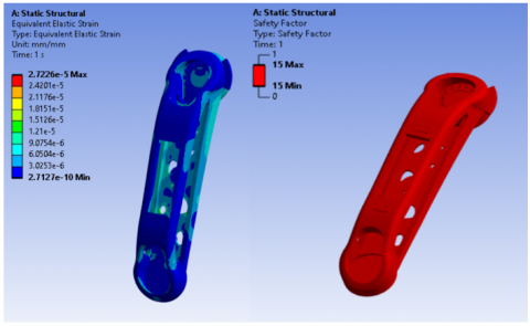
The safety factor is more than 15; that indicates that the arm is safe and the maximum elastic strain in this condition is 0.000027226 mm/mm according to the topology method, as shown in Figure 11.
Figure 9. The exclusion and design regions of the upper arm
Figure 10. Maximum von Mises stresses and total deformations of the robot’s upper arm
Figure 11. Safety factors and elastic strain of the robot’s upper arm
Figure 12. The robot's upper arm after topology optimization
Figure 13. The final view of the modified for KUKA KR 16
After the weight reduction by 40% of the modified upper arm illustrated in Figure 12, the KUKA KR 16 robot arm’s final view is also shown in Figure 13.
As the results from the three optimization methods size optimization, shape optimization, and topology optimization are compared, distinct advantages and disadvantages for each approach are revealed through a nuanced analysis. The process of size optimization is the focus of the discussion. Several advantages can be identified. The adjustment of dimensions is considered a relatively straightforward process, enabling the implementation of size optimization. The amount of material used in the design is directly influenced, thereby impacting costs. Several disadvantages are able to be identified. The complexity of the design is limited by the sole adjustment of size, as the overlooking of more intricate design changes may result in the limitation of its ability to address complex structural issues. Design changes are capable of being oversimplified: Opportunities for more nuanced improvements in performance may be overlooked due to the sole focus on size adjustments. The process of shape optimization involves the modification of a to in order to achieve optimal performance or desired characteristics. The advantages are being discussed. The external geometry is altered to enhance aerodynamics, resulting in a reduction of drag and an improvement in efficiency. Stress concentrations are addressed and mitigated in specific areas, thereby contributing to improved structural performance. Several disadvantages are able to be observed. The implementation of shape modification involves a complex process that potentially requires the utilization of advanced simulations and analyses. Certain applications are currently limited. The effectiveness of the application is contingent upon its usage, with a diminished impact being observed in certain scenarios. Topology optimization is a method utilized in engineering and design to optimize the layout or configuration of a structure or system. Several advantages can be identified. The holistic approach in the comprehensive distribution of materials is enabled by the identification of optimal material placement throughout the design space. Complex structural issues are addressed by this product, making it ideal for intricate designs. These issues are extended beyond mere adjustments in size or shape. Several disadvantages are to be observed. Advanced computational resources and time are necessitated by the computational intensity of iterative simulations, resulting in an escalation in resource intensity. The potential for over-optimization is being considered. Challenges may be encountered in the maintenance of the necessary stiffness and structural integrity due to the excessive removal of material. Topology optimization is frequently preferred due to its numerous advantages and potential benefits. The achievement of a comprehensive improvement of the entire design is enabled by the utilization of topology optimization, as it concurrently addresses both size and shape considerations. The attainment of a balanced trade-off between structural integrity, weight reduction, and cost-effectiveness is allowed by the optimal distribution of material through topology optimization. Several considerations need to be accounted for. The choice between these optimization methods is determined by the specific goals, constraints, and intricacies of the robot arm design. Synergistic benefits are offered by a hybrid approach that combines elements of each optimization method. In conclusion, the preferable choice among size, shape, and topology optimization is determined by the specific design context and goals. Topology optimization is favored in scenarios where a holistic improvement is considered paramount, due to its capability to address complex structural issues and optimize material distribution. However, the decision should be made based on a careful consideration of the specific requirements and constraints of the robot arm design.
The focus of this study is to improve the upper arm's design for the KUKA KR16 industrial robot, specifically for arc welding applications, to obtain better mechanical properties compared to the original one. The design parameters of the KUKA KR 16 are established based on the required operation range, according to the company's data [19]. Before designing the original robotic arm using CAD software, namely SolidWorks. Following the design process, the numerical analyses are carried out with the ANSYS software to obtain more precise findings. Then the upper arm, which is the most critical component of the robotic arm, is modified using the size, shape, and topology optimizations to improve the original robotic arm, performing the same modeling and analyzing steps mentioned above. The results of the analyses show that the KUKA KR 16 robotic arm satisfied the maximum von Mises, maximum deformation, maximum elastic strain, and safety factor. By comparing the three types of optimizations that are done in this study, it is found that topology optimization is the best way to distribute the useful material in the design space with the optimal solution due to its lighter mass and cost-saving benefits in manufacturing. Improvement in size and shape is not relied upon here, although the emphasis is significantly reduced. During the size optimization process, the stress is observed to be 0.021059 mm. During the shape optimization, the stress is observed to be 0.019332 mm, whereas during the topology advantage, the stress is determined to be 0.027966 mm. However, the encounter with failure was not observed as the safety factor in the security situation and was found to be lower than the cost of manufacturing, resulting in its adoption. Agility is enhanced. The agility of the robot arm is significantly improved by a 40% reduction in weight, thereby facilitating faster and more precise movements. Improved responsiveness is contributed by lower weight, which is crucial for efficient operation. With a 40% lighter mass, the robot arm is rendered notably more energy-efficient, as less power is required for its movements. The stress on mechanical components is minimized by the substantial weight reduction, which has the potential to extend their lifespan. A consideration of structural integrity is being made. The ability of the robot arm to withstand force and torque without collapsing is demonstrated by maintaining structural integrity through topology optimization. This ensures that the weight reduction is aligned with structural stability. The topology method makes a reduction in weight of 40% in the upper arm, and it concludes a total reduction of more than 9.745% of the robotic arm, which reaches a weight of 212.098 kg overall. Moreover, the topology optimization demonstrates the robot arm's ability to withstand force and torque without collapsing.
[1] Alghloom, A., Ay, S. (2022). Design and analysis of a novel robotic arm for high precision micro friction stir welding. AURUM Journal of Engineering Systems and Architecture, 6(1): 75-91. https://doi.org/10.53600/ajesa.1067298
[2] Ceccarelli, M. (2003). Low-cost robots for research and teaching activities. IEEE Robotics & Automation Magazine, 10(3): 37-45. https://doi.org/10.3390/robotics12040091
[3] Tavares, P., Costa, C.M., Rocha, L., Malaca, P., Costa, P., Moreira, A.P., Sousa, A., Veiga, G. (2019). Collaborative welding system using BIM for robotic reprogramming and spatial augmented reality. Automation in Construction, 106: 102825. https://doi.org/10.1016/j.autcon.2019.04.020
[4] Lijin, F., Longfei, S. (2017). Design of a novel robotic arm with non-backlash driving for friction stir welding process. The International Journal of Advanced Manufacturing Technology, 93: 1637-1650. https://doi.org/10.1007/s00170-017-0617-2
[5] Yao, P., Zhou, K., Lin, Y., Tang, Y. (2019). Light-weight topological optimization for upper arm of an industrial welding robot. Metals, 9(9): 1020. https://doi.org/10.3390/met9091020
[6] Srinivasulu, R., Rao, Y.S., Vempati, S., Haribabu, U. (2022). Designing arc welding application using Yaskawa robot. International Journal of Mechanical Engineering, 7(2): 2493-2510.
[7] Ali, Z., Sheikh, M.F., Al Rashid, A., Arif, Z.U., Khalid, M.Y., Umer, R., Koç, M. (2023). Design and development of a low-cost 5-DOF robotic arm for lightweight material handling and sorting applications: A case study for small manufacturing industries of Pakistan. Results in Engineering, 19: 101315. https://doi.org/10.1016/j.rineng.2023.101315
[8] Ding, D., Shen, C., Pan, Z., Cuiuri, D., Li, H., Larkin, N., Van Duin, S. (2016). Towards an automated robotic arc-welding-based additive manufacturing system from CAD to finished part. Computer-Aided Design, 73: 66-75. https://doi.org/10.1016/j.cad.2015.12.003
[9] Silva-Magalhães, A., Cederqvist, L., De Backer, J., Håkansson, E., Ossiansson, B., Bolmsjö, G. (2019). A friction stir welding case study using temperature controlled robotics with a HPDC cylinder block and dissimilar materials joining. Journal of Manufacturing Processes, 46: 177-184. https://doi.org/10.1016/j.jmapro.2019.08.012
[10] Srinivas, G.L., Javed, A. (2021). Topology optimization of KUKA KR16 industrial robot using equivalent static load method, 2021 IEEE International IOT. In Electronics and Mechatronics Conference (IEMTRONICS), Toronto, ON, Canada, pp. 1-6. https://doi.org/10.1109/IEMTRONICS52119.2021.9422633
[11] Song, S.H., Choi, J.O., Lee, S. (2022). The current state and future directions of industrial robotic arms in modular construction. Civil and Environmental Engineering and Construction Faculty Research, pp. 336-343.
[12] Al-Karkhi, N.K., Abbood, W.T., Khalid, E.A., Jameel Al-Tamimi, A.N., Kudhair, A.A., Abdullah, O.I. (2022). Intelligent robotic welding based on a computer vision technology approach. Computers, 11(11): 155. https://doi.org/10.3390/computers11110155
[13] Loukas, C. (2022). Holistic and adaptive robotic welding. University of Strathclyde. https://doi.org/10.48730/0x2d-ks44
[14] Tejaswini, P., Achutha, M.V., Doddagatte, A. (2022). Development and integration of laser sensor tracking system in robotic arm for path correction during welding operation. IAES International Journal of Robotics and Automation, 11(3): 196-204. https://doi.org/10.11591/ijra.v11i3.pp196-204
[15] Zheng, C., An, Y., Wang, Z., Wu, H., Qin, X., Eynard, B., Zhang, Y. (2022). Hybrid offline programming method for robotic welding systems. Robotics and Computer-Integrated Manufacturing, 73: 102238. https://doi.org/10.1016/j.rcim.2021.102238
[16] Shen, Y., Hu, M., Teng, K., Zhang, C., Yang, X., Liu, W. (2022). Research on positioning accuracy of welding robot based on visual data mining and pattern fusion analysis algorithm. In 2022 International Conference on Inventive Computation Technologies (ICICT), Nepal, pp. 702-705. https://doi.org/10.1109/ICICT54344.2022.9850879
[17] Qi, A.N.W., Voon, K.L., Ismail, M.A., Mustaffa, N., Ismail, M.H. (2015). Design and development of a mechanism of robotic arm for lifting part 1. In 2nd Integrated Design Project Conference, pp. 1-14. https://doi.org/10.13140/RG.2.1.4517.3845
[18] RoboDK Global. KUKA-KR-16, Specifications. https://robodk.com/robot/KUKA/KR-16-2.
[19] Yağmur, H. (2020). KUKA industrial robotic ARM. 3D CAD Model Library. GrabCAD. https://grabcad.com/library/kuka-industrial-robotic-arm-1.