Sai Kham Le![]() | Jittraporn Wongsa-Ngam*
| Jittraporn Wongsa-Ngam*![]()
© 2024 The authors. This article is published by IIETA and is licensed under the CC BY 4.0 license (http://creativecommons.org/licenses/by/4.0/).
OPEN ACCESS
In a bolted rail joint, the two rail ends are connected with fishplates on both sides and adjusted with fishbolts. Such joints help to facilitate the smooth running of the train wheels over the joints. However, the lifetime of a bolted rail joint is shorter than the lifetime of a continuous rail because of the complex interactions that occur at the contact surfaces of the joint components and at the rail ends. In this paper, the bolted rail joint structure components are first modeled in ABAQUS/CAE. The effects of rail-end bolt hole position and bolt-hole clearance were considered in the rail. Then, finite element analysis (FEA) of the bolted rail joint assembly was performed to determine the stress, particularly on the upper fillet and bolt holes of the rail, as well as the vertical displacement of the rail end, when static loading was applied at the rail end. The numerical simulation results showed that the rail-end bolt hole positions affect to von-Mises stress and vertical displacement, whereas bolt-hole clearance has a relative minor effect on stress and vertical displacement. To avoid stress concentration that may cause further failure, the position of the rail-end bolt holes should be carefully considered.
bolted rail joint, bolt-hole position, bolt-hole clearance, displacement, finite element, stress
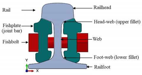
A bolted rail joint employs two fishplates to connect the two rail ends (named the sending and receiving rails) by adjustment with either four or six bolts. This setup ensures a smooth operation of train wheels, particularly in proximity to stations, transit points, switch points, crossings, curved tracks, and temporary installations along straight railways. However, a bolted rail joint undergoes a range of intricate interactions due to its numerous components and the presence of a gap between the rail ends. These complexities and discontinuities lead to elevated stress and strain on the rail joint components when the joint is exposed to loading and result in defects and collapses in the bolted rail joint. Their common defects in a bolted rail joint include head-web cracking or separation, rail bolt-hole cracking, joint bar cracking and broken or missing bolts [1, 2]. Eventually, these defects elevate the risk of train derailment. Therefore, a comprehension of the behavior of rail joints under various conditions is crucial to the minimization of defects and failures in bolted rail joints.
Many research projects have been undertaken in the study of the behavior of bolted rail joints under various conditions. Research has been done from various theoretical and experimental approaches, and numerical methods. Finite element analysis (FEA), one of numerical methods, is a popular and powerful tool that can be used to study the structural behavior of a complex joint, such as a bolted rail joint, under different scenarios. The influence of support configurations such as supported joint, near to the support joint, and suspended joint on the six-bolted rail joint are examined using FEA, and the stresses and strains of individual joint components were analyzed [3-5]. The FEA results indicated that the stresses and strains on individual components were reduced when the joint was a supported joint compared to the case of a suspended joint. Wondimu et al. [6] examined the stress distribution and the vertical displacement on the key joint components for four-bolted rail joint by considering the support configurations, the wheel load positions and train speed under static and dynamic loads. The findings indicated that the stresses on the upper fillet, bolt hole and vertical displacement at the rail end were increased under the static load applied on the suspended joint center. Zhu et al. [7] used numerical simulation to observe stress distribution and displacement with different variables; four joint bars, five support configurations, two load locations for 100-8 and 115 RE rails. The results found that the stress on the upper fillet and the rail-end bolt hole, and the vertical displacement were higher in the suspended joint when the static load was applied on the rail end. Additionally, a longer joint bar behaved similarly to a standard joint bar, whereas a thicker joint bar reduced both stress and vertical displacement compared to the standard joint bar. However, they did not discuss the influence of bolt-hole positions. Then, Le and Wongsa-Ngam [8] considered the influence of positions of rail-end bolt hole with two loading locations on stress distribution at areas of the upper fillet and the rail-end bolt hole for the four-bolted rail joint of UIC 60 rail. The results indicated that the stress values on both areas increased once the position of rail-end bolt hole was close to the rail edge.
Moreover, bolt conditions such as loosened and missing bolts are other factors that affected the structural performance of a rail joint. Ding and Dhanasekar [9] considered the effects of bolt pre-tension on the displacement of the sending plate when studying the flexural behavior of bonded-bolted butt joints under load applied on the mid-span of the joint. Then, Zhu et al. [10] considered the effects of bolt preloading (loosened, standard and over-tightened) and missing bolts in a six-bolted rail joint by studying the stress distribution and rail end vertical displacement under static loading conditions. Loosened bolt preloading and missing two bolts at the mid-span increased stress at the rail upper fillet and the bolt hole near the end and enhanced the displacement of the rail end. Furthermore, Samantaray et al. [11] considered two looseness of bolt preloading on the four-bolted rail joint under the static loads. The stress and deflection behavior of the rail joint components was presented.
According to previous works, the structural behavior including stress and displacement of the bolted rail joint have been reported by mainly considering the effect of rail configurations, preloading or positions of applied load for different types of rails. We also recognized that the clearances between bolt and hole from previous studies were different. However, the effect of clearance on the structural behavior of rail joints was under-researched.
This work was designed and proposed after an extensive literature review in which we sought to understand the structural response in terms of stress and deformation of the four-bolted rail joint. Three-dimensional (3D) finite element analyses (FEA) of a bolted rail joint under static loading was performed to investigate the effects of rail-end bolt hole positions and bolt-hole clearances on stress distribution (especially around upper fillet and bolt hole), and on vertical displacement of the rail end.
The design of a State Railway of Thailand (SRT) bolted rail joint, with components consisting of a BS 100 rail, fishplate (joint bar), fishbolt (bolt), and nut was modeled as a 3D finite element model (FE model) in Abaqus CAE, as shown in Figure 1. The BS 100 rail has a weight of 50.182 kg/m, and dimensions of 133.35 mm and 152.40 mm in width and height, respectively. The length of rail on each side of the joint is 6000 mm with a 6 mm gap between the two rail ends. The total length of the rail joint model is 12000 mm, which is long enough when considering boundary conditions of the finite rail member [12]. The fishplates are placed on both sides of the rail ends and fixed with four bolts by a 25.4 mm diameter bolt. The assembly of the bolt, nut, and washer is simplified to a single fishbolt to reduce the computational cost [10]. The dimensions of the sleeper are $2000 \mathrm{~mm} \times 272 \mathrm{~mm} \times 234 \mathrm{~mm}$ in length, width and height, respectively. The distance between adjacent sleepers from center to center is 600 mm. The rail, fishplates and bolts are made of steel, while the sleeper is made of concrete. The mechanical properties of the bolted rail joint components (rail, fishplates, and bolts) including the sleeper are summarized in Table 1 [13, 14]. Linear elastic material properties are performed for the rail joint components in this study.
Figure 1. The bolted rail joint of the model
Table 1. Materials properties of the rail joint components
|
Components |
Young Modulus (GPa) |
Yield Strength (MPa) |
Poisson Ratio |
Density kg. m-3 |
|
BS 100 Rail |
207 |
640 |
0.3 |
7800 |
|
Fishplate |
207 |
640 |
0.3 |
7800 |
|
Fishbolt |
207 |
640 |
0.3 |
7800 |
|
Sleeper |
40 |
46.6 |
0.18 |
1265 |
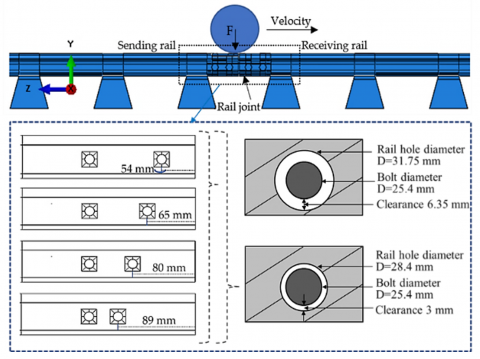
FE parametric analysis was performed by considering different positions of the rail-end bolt hole under a static wheel load. The rail-end bolt hole positions were the distance from the rail edge to the center of the rail-end bolt hole. The values of the variable positions were 54, 65, 80 and 89 mm in which value of 54 mm was designated by SRT, and the last three values were based on each previous studies [8, 10, 15].
Furthermore, the clearances for the rail between the bolt hole and the fishbolt were also considered in this study. The clearances selected were 6.35 mm as in the SRT design, and 3 mm as per the Ding and Dhanasekar model [9]. The parameters for the finite element numerical simulation were set as shown in Figure 2. Firstly, the rail-end bolt hole positions, i.e., 54, 65, 80, and 89 mm, were run with a clearance of 6.35 mm. Next, the bolted rail joint was re-modelled with the same rail-end bolt hole positions but with the clearance reduced to 3 mm.
Figure 2. A schematic of parametric studies in the FE model including a side view of the rail-end bolt hole positions and the clearances
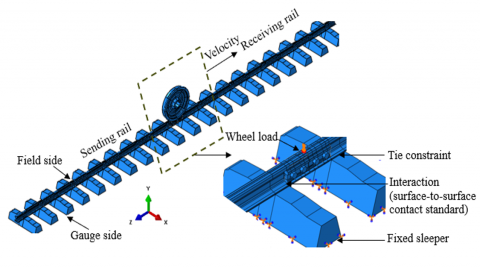
In the 3D FE model, the X, Y, and Z cartesian coordinates represents the lateral, vertical, and horizontal directions, respectively. The assembly model of the bolted rail joint and its boundary conditions are shown in Figure 3.
In this study, two steps of loading systems were considered in the setting up of the FE numerical simulation. Step 1 involved fishbolt preloading [10-12, 16]. The fishbolt preloading Pb is:
$P_b=\frac{T}{K_b D}$ (1)
where, T is the fishbolt torque, D is the fishbolt diameter and Kb is a coefficient (Kb=0.19-0.25). The parameters of T, D, and Kb were $500 \mathrm{~N}\cdot\mathrm{m}$, 25.4 mm, and 0.22, respectively. According to Eq. (1), the fishbolt preloading is 98.4 kN per bolt, which is in the range of 89.0-133.4 kN per bolt according to the AREMA Manual in Section 5, Section 5.5 for the track preload [17]. Therefore, a preloading of 98.4 kN was applied to the internal cross-sections of the four fishbolts at the bolted rail joint [18].
Step 2 involves the static wheel load. The SRT train wheel load was designated as 20 t per axle. Due to the symmetry of the railway tracks, half of the railway line was considered as a single straight railway track in the FE simulation. Then, the static wheel load became 10 t. It is well established that a static wheel load is smaller than a load under dynamic conditions. To be more realistic loads, the applied wheel load equals to a static wheel load times the loading factor. The loading factor equation was applied as the Talbot theory which required the parameters of wheel diameter and velocity [19]. The wheel diameter (1067 mm) and velocity ($120\mathrm{k}\cdot\mathrm{m}/\mathrm{h}$) are based on the SRT design. The loading factor 1.3 is considered. Therefore, a total wheel load of 13 t (equivalent to 130 kN) was used for the simulation. This wheel load was applied on the sending rail end as the ellipsoidal Hertzian pressure distribution [20], as shown in Figure 3.
The contact interactions between the bolted rail joint components used an automatic surface-to-surface contact standard in an interaction module. Master and slave surfaces were created on the contact surfaces of the components. For the normal and tangential contact of the components, Coulomb’s law friction coefficient was selected as 0.3 [21] and the Penalty method was used. A hard contact pressure-overclosure relationship was used for two contact surfaces to reduce the penetration of slave nodes into the master surface [9, 22, 23]. In the boundary conditions, the bottom surface of the sleeper was fixed [24], and the rail was allowed to move in the vertical direction to see the rail joint vertical displacement which is shown in Figure 3. The last consideration, a tie constraint was used to represent the E-clip fastening system of the rails and the sleepers.
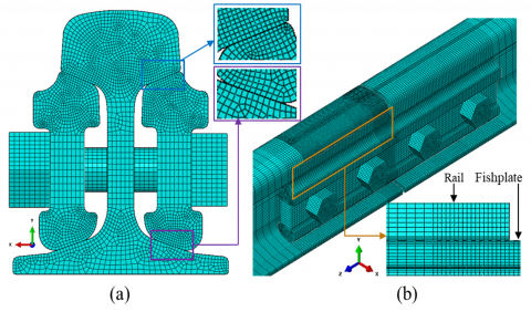
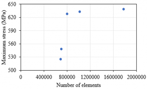
The element type selected for all the solid finite element models was an eight-node brick element (C3D8) to enhance the calculation time. A high density of mesh size was developed in the rail joint region to get accurate result, and a coarse one was selected for the other area as shown in Figure 4. Mesh convergence analyses were conducted to evaluate mesh sensitivity. Five different element numbers: 692079, 701091, 799092, 1016064, and 1776470, were used to observe the maximum stress on the rail section. The relationship between the maximum stress and the element numbers was plotted in Figure 5. The result shows that the stress value is converging to the steady at the element number of 799092. However, for computational accuracy the element number of 1776470 was selected.
Figure 3. The boundary conditions of the bolted rail joint
Figure 4. FE mesh model (a) cross-sectional view, and (b) isometric view
Figure 5. Mesh convergence analysis
5.1 Stress on the rail end surface
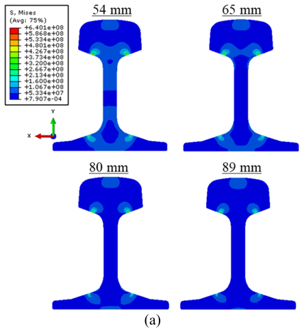
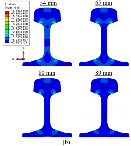
The stress distributions over the surfaces of the rail-ends for various positions of the rail-end bolt holes under static loading applied at the rail ends of the sending rails with bolt-hole clearances of 6.35 mm and 3 mm are depicted in Figure 6(a) and Figure 6(b), respectively. Overall observation, there is a variation of stress over the rail end surfaces when the positions of the rail-end bolt holes were changed. Stress values on the web vary inversely with the position of rail-end bolt holes. The areas of higher stress value (indicated as light blue in the range of 84-639 MPa) become reduced when the rail-end bolt hole position increases from 54 mm up to 89 mm for a bolt hole clearance of 6.35 mm, shown in Figure 6(a). Moreover, the same tendency is observed for the case of a clearance of 3 mm, shown in Figure 6(b). It is noticed as well that stress concentration occurs in the regions of contact surface such as the railhead, the head-web (upper fillet), and the foot-web (lower fillet). The maximum values of von-Mises stress for the upper fillet and lower fillet are shown in Table 2. Three important findings emerge from the data in Table 2. First, for all cases, the maximum levels of von-Mises stress on the rail end surface at the upper fillet are substantially more than those at the lower fillet. This result is consistent with a previous study [8] of a UIC 60 rail model. Second, the maximum von-Mises stress at the rail end surface tends to decrease when the position of the rail-end bolt hole is further away from the rail end. Third, by changing the bolt-hole clearance from 6.35 mm to 3 mm, the maximum stress values at the upper fillet and the lower fillet slightly decrease.
Figure 6. Stress distribution on the rail end surface for various positions of rail-end bolt hole with the clearance of (a) 6.35 mm and (b) 3 mm
Table 2. The maximum stress on the upper and lower fillets of the rail end
|
Rail End Bolt Hole Positions (mm) |
Maximum von-Mises Stress (MPa) |
|||
|
Clearance 6.35 mm |
Clearance 3 mm |
|||
|
Upper fillet |
Lower fillet |
Upper fillet |
Lower fillet |
|
|
54 |
639.07 |
305.22 |
628.49 |
298.96 |
|
65 |
565.19 |
279.13 |
556.65 |
274.05 |
|
80 |
482.29 |
237.89 |
457.30 |
231.76 |
|
89 |
436.74 |
220.90 |
425.44 |
217.91 |
5.2 Stress in the rail web
In this section, stresses around the bolt hole and stresses along the head-web (upper fillet) in the rail are discussed in detail as follows.
5.2.1 Stress around the bolt hole
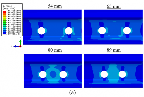
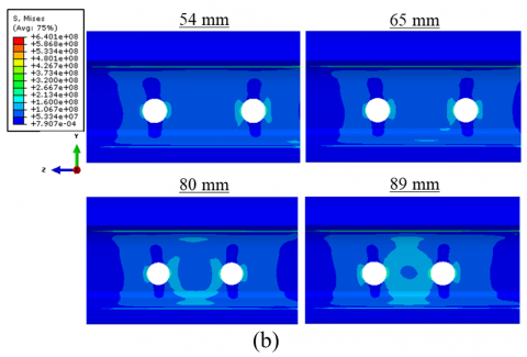
The stress distribution at the rail web along the Y-Z plane on gauge side when a static load is applied at the rail-end for various rail-end bolt hole positions with a clearance of 6.35 mm and 3 mm are shown in Figure 7. It is clear that the position of the rail-end bolt hole influences the stress distribution on the web, especially around the hole. At a rail-end bolt hole position of 54 mm, a higher stress area (seen as a light blue color) with the range of 84-224 MPa occurs around the hole in the range of approximately 0°±45° to the longitudinal axis. This is consistent with the cracks commonly seen in the rail-bolted hole where the cracks usually initiate at roughly 45° to the neutral axis of the rail [15]. Cracks around the bolt holes can also grow at an angle of 0° when crack initiation is caused by vertical stress due to fishplate restraint [25]. When the position of the rail-end bolt hole is increased from 54 mm to 89 mm, the higher stress area gradually expands and lays between two holes. Overall trends for the influence of a rail-end bolt hole positions are similar in both bolt-hole clearances of 6.35 mm and 3 mm.
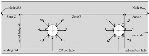
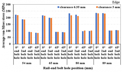
In more detail, the von-Mises stress values around the edge of the rail-end bolt hole and 2nd bolt hole are observed at 0° and 45° positions to the longitudinal axis, as depicted in Figure 8. Then, the von-Mises stress values at 0° and 45° are measured and illustrated as shown in Figure 9. The results suggest that the average von-Mises stress values at 0° are higher than those at 45° for all conditions. This observation is consistent with Kataoka et al. [26], who measured stress at 0° and 45° around the 1st and 2nd holes with various fastening torque of 500 N×m, 250 N×m and 50 N×m. They reported that the values of maximum principal stress at 0° are higher than that of at 45° for all fastening torque conditions.
Figure 7. Stress distribution in the rail web for all the rail-end bolt hole positions (a) the clearance 6.35 and (b) 3 mm
Moreover, the results reveal that the bolt-hole clearance does not noticeably affect stress around the hole. In addition, the position of rail-end bolt hole affects the stress difference between the rail-end and the 2nd bolt holes at an orientation of 0°. At the position of 54 mm, the average von-Mises stress at the rail-end bolt hole is higher than that at the 2nd bolt hole. This stress difference is reduced when the position is increased. For example, in the case of the rail-end bolt hole position being 89 mm, the average stress values in both orientations for two bolt holes are almost identical.
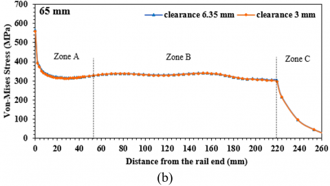
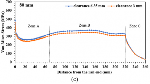
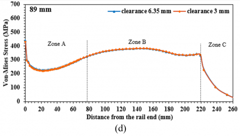
5.2.2 Stress along the rail upper fillet
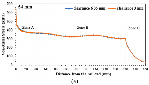
To observe the von-Mises stress along the upper fillet, the stresses are measured from node 0 mm to 253 mm, as depicted in Figure 8. For investigation, the distance along the upper fillet is divided into three zones; Zone A is the segment before the rail-end bolt hole, Zone B is the segment from the rail-end bolt hole to the end of contact with the fishplate, and Zone C is the segment beyond the end of the fishplate. The von-Mises stress values along the upper fillet are plotted against the distance from the rail end as displayed in Figure 10 for different conditions of the rail-end bolt hole positions with clearances of 6.35 mm and 3 mm. It is apparent from Figure 10 that the highest stress along the upper fillet appears at the rail end (node 0) with magnitudes of 639, 565, 482, and 437 MPa for positions of 54, 65, 80 and 89 mm, respectively. The highest stress appears at the rail end where the load is applied. The application of the load at this point clearly resulted in the highest contact stress between rail end and fishplate [6-8, 10]. The stress profile along the upper fillet for the position of 54 mm is similar to that for 65 mm (Figures 10(a) and (b)), where stress is at its highest value at the rail end then suddenly decreases to a certain value in Zone A, maintains its value in Zone B (between two holes) and then suddenly decreases in Zone C, where the fishplate ended. Figures 10(c) and (d) show the stress profiles along the upper fillet for the positions of 80 mm and 89 mm, respectively. Their stress trends show similar features in that for both, in Zone A, following the maximum stress at the rail end, the stress drops immediately to a minimum and then gradually increases. This fluctuation of stress in Zone A is probably mainly due to variable bending stress in this zone. The longer part of rail before the rail-end bolt hole in the cases of 80 mm and 89 mm behaves like a typical cantilever beam. It is clear from the results that the rail-end bolt hole position affects the von-Mises stresses along the upper fillet. However, it seems that the von-Mises stress in this area is insensitive to the clearance.
Figure 8. Schematic diagram for stress measurement on the rail
Figure 9. The stress in the rail-end and 2nd bolt holes for all the rail-end bolt hole positions with bolt hole clearances of 6.35 mm and 3 mm
Figure 10. The von-Mises stress along the rail upper fillet for the positions of (a) 54 mm, (b) 65 mm, (c) 80 mm, and (d) 89 mm with a bolt-hole clearance of 6.35 mm and 3 mm
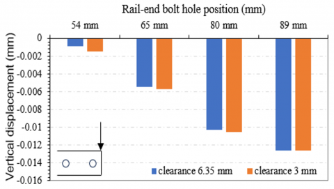
5.3 Vertical displacement at the rail end
In this section, the vertical displacement at the edge of railhead under static loading applied at the sending rail end for different rail-end bolt hole positions and two different bolt-hole clearances is investigated and reported. The results can be seen in Figure 11. It is noticeable that vertical displacement at the rail end increases as the rail-end bolt hole position increases. The lowest vertical displacement is observed when the rail-end bolt hole position is 54 mm while the highest displacement is noted when the position was 89 mm, for both bolt-hole clearances. This phenomenon might be mainly caused by the bending moment when the wheel load applied to the rail end. A longer distance from the rail end induces a higher bending moment, eventually the vertical displacement is increased. Moreover, the longer length is like the case of two missing bolts at the joint center in earlier research by Zhu et al. [10] who observed that two missing bolts caused significant rail-end vertical displacement increase. A higher vertical displacement presents a high risk for the railhead, upper fillet, and rail-end bolt hole. Higher vertical displacement or mismatch in the sending rail results in defects in the receiving rail edge because the wheel/rail impact force is increased when the wheel runs over the bolted rail joint under dynamic conditions [21]. Additionally, it can be seen in Figure 11 that the bolt-hole clearance slightly influences the vertical displacement of the railhead at the edge. The vertical displacement for a clearance of 3 mm is a little higher than that for a clearance of 6.35 mm. However, the effect of clearance became less noticeable as the position of rail-end bolt hole increased.
Figure 11. The vertical displacement at the edge of railhead for all the positions analysis with the clearance 6.35 mm and 3 mm
The bolted rail joint was performed using finite element analysis, taking into account the influence of rail-end bolt hole positions and clearances under static wheel loads. The results indicate that under a vertical wheel load applied at the end of sending railhead, stress concentrations appear at the railhead (at load applied), lower fillet, and especially at the upper fillet and the bolt holes. It is also found that values of von-Mises stress on the rail and vertical displacement at the rail end are dependent on the rail-end bolt hole position. As the position increases the maximum stress at the upper fillet decreases but the displacement at the rail end increases.
However, the bolt-hole clearance has insignificant effects on von-Mises stress and vertical displacement in this study. Therefore, to avoid stress fluctuation or stress concentration at the upper fillet and bolt hole that might cause further failure, i.e., upper fillet separation and bolt hole cracking, the position of rail-end bolt hole should be carefully considered.
In upcoming research, the author plans to investigate the stress exerted on the railhead near the joint gap at the rolling contact patch of the wheel and rail. Further research aims to assess the fatigue life of the railhead near the rail joint by subjecting it to dynamic wheel load conditions in a finite element numerical simulation.
This work is supported by King Mongkut’s Institute of Technology Ladkrabang (Grant No.: KDS 2019/009).
|
P |
fishbolt preload, N |
|
T |
torque of the fishbolt, N×m |
|
D K |
fishbolt diameter, m. coefficient of the fishbolt |
|
Subscripts |
|
|
b |
fishbolt |
[1] Jeong, D.Y., Bruzek, R., Tajaddini, A. (2014). Engineering studies on joint bar integrity: Part I—Field surveys and observed failure modes. In ASME/IEEE Joint Rail Conference, vol. 45356, p. V001T01A001. https://doi.org/10.1115/JRC2014-3706
[2] Carolan, M.E., Jeong, D.Y., Perlman, A.B. (2014). Engineering studies on joint bar integrity: Part II—Finite element analyses. In ASME/IEEE Joint Rail Conference, vol. 45356, p. V001T01A002. https://doi.org/10.1115/JRC2014-3708
[3] Guta, S., Tilahum, D. (2016). Stress analysis of rail joint under wheel load. International Journal of Innovative Science, Engineering & Technology, 3(6): 526-543.
[4] Piyush, Gupta, S. (2017). Stress analysis of bolted rail joint using finite element analysis. International Journal of Research in Engineering and Technology, 6(1): 38-46.
[5] Gardie, E., Dubale, H., Tefera, E., Bezzie, Y.M., Amsalu, C. (2022). Numerical analysis of rail joint in a vertical applied load and determining the possible location of joints. Forces in Mechanics, 6: 2666-3597. http://doi.org/10.1016/j.finmec.2021.100064
[6] Wondimu, A., Alemu, N., Regassa, Y. (2019). Modeling and simulation of rail end bolt hole and bolted rail joint by FEM. International Journal of Innovative Science, Engineering & Technology, 6(5): 175-186.
[7] Zhu, K., Qian, Y., Edwards, J.R., Andrawes, B.O. (2017). Finite element analysis of rail-end bolt hole and fillet stress on bolted rail joints. Journal of the Transportation Research Board, 2607(1): 33-42. https://doi.org/10.3141/2607-06
[8] Le, S., Wongsa-Ngam, J. (2021). Stress analysis in upper fillet and rail-end bolt hole at rail joint. IOP Conference Series: Materials Science and Engineering, 1137(1): 012050. https://doi.org/10.1088/1757-899X/1137/1/012050
[9] Ding, K., Dhanasekar, M. (2007). Flexural behavior of bonded-bolted butt joints due to bolt looseness. Advances in Engineering Software, 38(8-9): 598-606. https://doi.org/10.1016/j.advengsoft.2006.08.023
[10] Zhu, K., Edwards, J.R. Qian, Y., Andrews, B. (2016). Finite element analysis of the effects of bolt condition on bolted rail joint stresses. Journal of the Transportation Research Board, 2545(1): 36-45. https://doi.org/10.3141/2545-05
[11] Samantaray, S.K., Mittal, S.K., Mahapatra, P., Kumar, S. (2019). Assessing the flexion behavior of bolted rail joint using finite element analysis. Engineering Failure Analysis, 104: 1002-1013. https://doi.org/10.1016/j.engfailanal.2019.06.057
[12] Mandal, N.K., Dhanasekar, M. (2013). Sub-modelling for the ratchetting failure of insulated rail joints. International Journal of Mechanical Sciences, 75: 110-122. https://doi.org/10.1016/j.ijmecsci.2013.06.003
[13] Sukhom, A., Jangchud, I., Pimsarn, M., Charoensuk, J., Treeporncharoen, V. (2018). Design of natural-rubber panel railroad crossing using finite element method. MATEC Web of Conferences, 192: 02056. https://doi.org/10.1051/matecconf/201819202056
[14] Wondimu, A., Alemu, N., Sivaprakasam, P. (2020). Study on the effect of dynamic load on rail joint bar by finite element method (FEM). Advances in Materials and Processing Technologies, 8(1): 1121-1134. https://doi.org/10.1080/2374068X.2020.1853496
[15] Mayville, R.A., Hilton, P.D. (1984). Fracture mechanics analysis of a rail-end bolt hole crack. Theoretical and Applied Fracture Mechanics, 1: 51-60. https://doi.org/10.1016/0167-8442(84)90020-X
[16] Mandal, N.K. (2015). Plastic ratchetting of railhead material in the vicinity of insulated rail joints with wheel and thermal loads. Wear, 330-331: 540-553. https://doi.org/10.1016/j.wear.2015.01.003
[17] Lanham, Md. (2005). American railway engineering and maintenance-of-way association (AREMA). Manual for Railway Engineering.
[18] Mandal, N.K. (2017). Ratchetting damage of railhead material of gapped rail joints with reference to free rail end effects. Proceedings of the Institution of Mechanical Engineers, Part F: Journal of Rail and Rapid Transit, 231(2): 211-225. https://doi.org/10.1177/0954409715625361
[19] Van Dyk, B.J., Edwards, J.R., Dersch, M.S., Ruppert Jr, C.J., Barkan, C.P. (2017). Evaluation of dynamic and impact wheel load factors and their application in design processes. Proceedings of the Institution of Mechanical Engineers, Part F: Journal of Rail and Rapid Transit, 231(1): 33-43. https://doi.org/10.1177/0954409715619454
[20] Mandal, N.K., Peach, B. (2010). An engineering analysis of insulated rail joints: A general perspective. International Journal of Engineering Science and Technology, 2(8): 3964-3988.
[21] Wen, Z., Jin, X., Zhang, W. (2005). Contact-impact stress analysis of rail joint region using the dynamic finite element method. Wear, 258(7-8): 1301-1309. https://doi.org/10.1016/j.wear.2004.03.040
[22] Pang, T. (2007). Studies on wheel/rail contact-impact forces at insulated rail joints. Master of Engineering dissertation. Centre for Railway Engineering, Central Queensland University, Australia.
[23] ABAQUS/CAE User’s Manual Book (Version 6.14).
[24] Mandal, N.K. (2014). On the low cycle fatigue failure of insulated rail joints (IRJs). Engineering Failure Analysis, 40: 58-74. https://doi.org/10.1016/j.engfailanal.2014.02.006
[25] Zerbst, U., Lundén, R., Smith, R. (2009). Introduction to the damage tolerance behaviour of railway rails - A review. Engineering Fracture Mechanics, 76: 2563-2601. https://doi.org/10.1016/j.engfracmech.2009.09.003
[26] Kataoka, H., ABE, N., Wakatsuki, O. (2002). Evaluation of service life of jointed rails. QR of RTRI, 43(3): 101-106. https://doi.org/10.2219/rtriqr.43.101