Yan Gu* | Jianhua Sun | Xiuwei Fu
© 2024 The authors. This article is published by IIETA and is licensed under the CC BY 4.0 license (http://creativecommons.org/licenses/by/4.0/).
OPEN ACCESS
In this paper, an intelligent brain emotional learning-based intelligent controller (BELBIC) technique is presented for the secondary frequency control of microgrid. The effects of renewable energy sources and load changes, power fluctuations and dynamic disturbances along with uncertainty affecting the microgrid frequency are all considered in the studied islanded microgrid. In the intelligent method for tuning and stabilizing the microgrid frequency, the learning of BELBIC technique is based on emotional factors and is able to adjust the microgrid frequency by including nonlinear terms and overcoming the effects of model uncertainty, disturbances, environmental changes and low inertia due to renewable energy sources. The behavior of the system against various changes and disturbances is investigated and compared with the optimal PID control methods. The advantages of the proposed method include low overshoot / undershoot, short settling time and minimization of frequency deviation. According to the simulation results obtained in different scenarios, the proposed control method shows good performance for network frequency stabilization.
frequency control, islanded microgrid, secondary control, renewable sources, intelligent technique
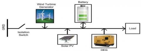
The issue of energy and how to supply it is one of the most important issues for researchers and one of the most important branches is related to power systems and electrical networks [1-4]. In recent years, the use of microgrids has been developing rapidly, especially in rural and inaccessible areas [5-7]. The concept of microgrid was first proposed by the Consortium for Electric Reliability Technology Solutions (CERTS) in 1998 [8, 9]. The purpose of introducing this concept in power generation systems was to increase reliability, flexibility, speed and ease in upgrading and updating, improving the economic and environmental indicators common in power generation systems and to increase efficiency. Microgrids are used in two modes: islanded mode or network-connected mode [10]. Of course, in some cases, the combined mode, i.e. switching between islanded mode and network-connected mode, has also been used. Due to their economic viability and less environmental damage, more islanded microgrids are used in recent years, especially in rural and remote areas [11, 12]. Figure (1) shows the microgrid schematic.
Due to the need for ancillary sources (such as wind or solar energy) to compensate the load fluctuations and production in the islanded mode, and mention that the regulation of frequency and voltage of the microgrid in the state connected to the network is supported by the main network, islanded microgrids are much more difficult to control than networked ones [13].
Low inertia, uncertainty and dynamic complexities are very important challenges of microgrids due to the presence of renewable resources in microgrids along with the nonlinear structure and alternating nature of DER. Also, energy storage is very important in microgrids due to the low inertia of the resources, i.e. the slow response time. Of course, the need for storage resources to improve the performance and reliability of the system in the event of an emergency such as load breakdowns or power outages is very important. Economic and environmental constraints have the greatest impact on the choice of distributed resources for an islanded microgrid system. Of course, it is necessary to state that the power generated by the distributed sources depends on the weather conditions, so they cannot be used in secondary frequency control.
If there is no match between load and generation, the voltage and frequency of the microgrid will be different from the nominal value, and this deviation can even lead to the shutdown of the microgrid. One of the most important study challenges in microgrids is finding a way to prevent the frequency deviation of microgrids in the islanded mode [14-16]. Diesel turbines and diesel engine generators, which typically supply electricity to compensate for demand shortages, have a low impact factor on the load which can lead to system shutdowns and intensify system low inertia and consequent large fluctuations [17]. However, there is still a slow response time and a lack of microgrid control against sudden changes in load and power [13]. In microgrids, similar to conventional power grids, there is a hierarchical approach. The three main control levels are regional or primary control, secondary control and general control [18-20]. When oscillation occurs during power generation and consumption in the microgrid system, the controller must return the frequency to the nominal value. The reference to the nominal value of the frequency is made in the secondary controller. The secondary control must ensure the compatibility of the optimal microgrid request with the set points of the microgrid and adjust the voltage and load frequency deviations to zero, after changing the load or generation [21].
Two centralized and decentralized structures are introduced for secondary control in [22, 23], the centralized design is based on the microgrid central controller and the decentralized design is with the possibility of interaction of different units within the microgrid. The centralized structure is usually more suitable for the islanded microgrid used in this paper, and the decentralized structure is used for the network-connected microgrid. As mentioned, an independent microgrid can consist of renewable energy sources to compensate a strong shock to the microgrid power because of irregular wind speed (when using wind energy source) and deflection of solar radiation (when using solar energy). On the other hand, it was stated that the diesel engine generator, due to its small capacity, reduces the inertia of the system and will lead to large and severe fluctuations in the system [24]. Serious concerns regarding to the observation of frequency deviations and voltage fluctuations in the microgrid system have been investigated in [25, 26].
The dependence of renewable sources on nature and the lack of support for the diesel generator to respond to the demand for microgrid power to sudden changes due to longer time response, has led to the use of battery energy storage system for rapid system balance. We need a controller to ensure the adjustment of the microgrid frequency deviation for any change in source or load and the optimal compatibility between the need and the set points of the microgrid [27].
Due to these advantages, in addition to advanced measurement in the distribution system, advanced communication technologies, modern control strategies, the conventional structure of the distribution system to the multi- network system have been improved over the past decades [28].
According to what has been said so far, in order to reduce fluctuations and to have sufficient confidence in the optimal dynamic performance of the islanded microgrid system in the presence of parametric uncertainty and irregular power supplies RES, we have to use a load frequency controller. These facts indicate that for the stable operation of the microgrid system, we must use an efficient and appropriate load frequency control method. Different control methods, including meta-innovative or traditional intelligent controllers, have been introduced to adjust the microgrid frequency according to the nominal frequency of the system. Metaphorical techniques fall into three general categories, including evolutionary algorithms, swarm intelligence algorithms (SI), and physics-based algorithms [29].
In evolutionary algorithms, the search for the optimal solution is based on evolutionary principles found in nature. Differential evolution, genetic programming, evolutionary programming and bio-based optimization can be mentioned as some examples of evolutionary algorithms. Physics-based algorithms are written based on the laws of physics. Algorithms such as galaxy based search, gravitational search algorithm, black hole algorithm, big-bang big-crunch algorithm and Ray optimization algorithm are among this section. Others use meta-innovative methods based on crowded intelligence techniques, including the social behavior of groups and herds. Methods such as particle swarm optimization (PSO), gray wolf algorithm (GWO), firefly algorithm, Bat algorithm, Krill Flock algorithm, and cuckoo search algorithm are some of the most popular SI-based algorithms. PSO is perhaps the most popular method [30].
Accordingly, some aspects of secondary control in microgrids are discussed in [31-34]. A report on intelligent and classical frequency control methods is presented in the following articles. Authors in [35] used the H-Infinity controller to minimize fluctuations. The meta-heuristic optimization algorithms are introduced in [31, 32] to adjust the frequency deviations such as Hopfield fuzzy-neural method and particle swarm optimization combination. To regulate PID gains, techniques based on aggressive intelligence are introduced in [36]. In [37-39] the technique is based on PI controller and in [40] controller is based on Ziegler-Nichols. In [41, 42] to determine the PID parameters to control the frequency in the presence of uncertain parameters, the combination of H2 / H-infinity and PSO combined with H2/H- infinity have been used. In [43], gray wolf optimization has been used to control the automatic production of the interconnected power system range. Authors in [44, 45] have been used genetic algorithm and biogeographical optimization, respectively. [46] proposed load frequency control based on the internal model. In [47] a multiple system including wind turbine generator and diesel engine generator and fuel cell and eco-electrolysis, which uses hydrogen produced by eco- electrolysis as fuel cell input, with PI controller are trying to stabilize the frequency.
With all the controllers designed and introduced, the research continues into a newer controller that performs better. In this article, we use the BELBIC method to address the challenges. This method is a kind of situation-based learning that is expressed in simple language. A type of conditional learning that is regulated by external emotional stimuli such as rewards and punishments received from various real-life situations. Because these external emotional stimuli can provoke and create different internal emotional states such as joy, sadness and fear, which affect our future decisions. Although traditional and classical controllers have been used extensively throughout the history of control science due to their easier construction and adjustment of workstations in industrial control systems, but their characteristics are always degraded due to changes in device parameters and set points. Therefore, in recent decades, to solve the problems of these controllers, we have seen their development by combining them with different adaptive control schemes [48-49]. Advances in soft computing techniques have been the main reason for designing intelligent control techniques such as neural networks, fuzzy logic or genetic algorithms, etc., which have been successfully implemented in various applications [50-52]. In this regard, the use of human emotional behavior was modeled in [53-54] and proposed in BELBIC method [55] and modifications were made on it [56].
The proposed BELBIC control method for microgrid frequency regulation is an intelligent learning-based technique and is able to handle the following challenges simultaneously. 1- Nonlinear dynamics of islanded microgrid in the presence of different elements; 2- Low inertia due to energy sources; 3- Distributed generation due to renewable and non-renewable sources; 4- Model parametric uncertainty; 5- Generation changes due to environmental changes; 6- Load changes due to consumer behavior; 7- Other Disturbances in the microgrid system. Taking into account the above, the proposed BELBIC method is able to quickly adjust the microgrid frequency and eliminate its deviations which ultimately offers better performance than other compared methods in terms of fluctuations, settling time, overshoot or undershoot and other characteristics.
The rest of this article is organized as follows: After introducing some of the abbreviations used in this study in the following, the modeling of microgrid is presented in the second part and in the third part, the BELBIC control method is described. The fourth part presents the simulation results of the proposed model in three different scenarios and in the fifth part, the conclusion and the path of future studies are presented.
MG: microgrid; RES: Renewable energy sources; KE: Gain of DEG; BESS: Battery Energy Storage System; KBES: Gain of BESS; LFC: Load Frequency Control; TWTG: Time constant of WTG; DG: Distributed Generation; KWTG: Gain of WTG; SPV: Solar Photovoltaic; A: Swept area; DEG: Diesel Engine Generator; BELBIC: brain emotional learning-based intelligent controller; PSO: particle swarm optimization; TBES: Time constant of BESS; ACE: Area Control Error; TE: Time constant of DEG; FC: Fuel Cell; β: blade pitch angle; WTG: Wind Turbine Generator; CP: Performance coefficient; ΔF1: Frequency deviation in microgrid-1; ΔPWT: Change in output wind power; ρ: air density factor; λ: tip speed ratio; Vrated: nominal wind speed; Δψ: Change in solar radiation; R1: Speed regulation constant of microgrid-1; VW: wind speed; R2: Speed regulation constant of microgrid-2.; ΔPC: Control signal to governor; Psize: Population size; PID controller: Proportional- Integral-Derivative controller; ΔPL: Change in Load; T12: Synchronizing coefficient between microgrid-1 and microgrid-2; iter: Current iteration; GWO: Grey wolf optimization; itermax: Maximum iterations; Kpmax: upper bound of proportional gain ; Kpmin: lower bound of proportional gain; Kimax: upper bound of integral gain; Kimix: lower bound of integral gain; Kdmax: upper bound of derivative gain; Kdmin: lower bound of derivative gain; ΔPTie–line: incremental change in tie line power exchange between microgrid-1 and microgrid-2; ΔPDG: Change in DEG output power; ΔPBES: Change in BESS power; T1: Governor Time constant; ΔPPV: Change in Solar power; T2: Transportation delay time constant; Prated: Rated wind power output; D: Load damping constant; PWT: Power from wind Turbine; H: Inertia Constant.
The book size should be in A4 (8.27 inches × 11.69 inches). Do not change the current page settings when you use the template.
In this paper, a system is investigated which forms a centralized islanded microgrid system and connects small loads through feeders to distributed micronutrients such as micro turbines, DEG, BESS, WTG and PV.
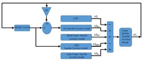
A simple structure of the microgrid is shown in Figure (1). Figure (2) also shows an islanded microgrid block diagram. In the studied microgrid system, the load demand is normally supplied by RES and the system consists of a DEG, WTG, solar photovoltaic and BESS. Due to the intermittent nature of RES resources, there is a possibility of not being able to meet the load demand, and a diesel generator has been used as a load demand balancer to enhance the reliability of the system. The BESS system is also used for short-time support to ensure the dynamic stability of the system. Excess RES power is used to charge the battery. Another important point is the possibility of expanding the sub-network system in case of increasing load demand. The controller output is connected to the diesel generator system and BESS, while reduce the frequency deviation, it also has a faster steady state response.
Figure 1. Schematic view of microgrid system
Figure 2. Block diagram of islanded microgrid
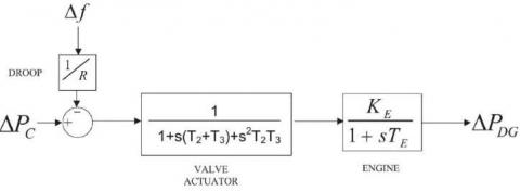
2.1 Diesel engine generator
The block diagram of the first-order DEG transfer function is shown in Figure (3). The task of the DEG unit in an islanded microgrid, given the inevitable changes in solar and wind energy, is to maintain a balance between electricity demand and its generation through the control of the governor speed.
Figure 3. Block diagram of diesel engine generator transfer function model
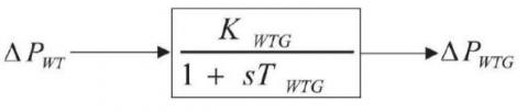
2.2 Wind turbine model
The wind turbine converts the kinetic energy of the wind into mechanical energy and this mechanical energy is transferred to the generator rotor. The generator shaft mechanism is used to convert the mechanical energy generated by the rotor into electrical energy. Eq. (1) indicates the mechanical output of a wind turbine related to ratio of tip speed $\lambda$, air density coefficient $\rho$, wind speed $V$, power factor $C_P$, area in square meters $A$ and pitch angle $\beta$ [57].
$P_{W T}=\frac{1}{2} \rho A C_P(\lambda, \beta) V_W^3$ (1)
$P_{W T}=\left\{\begin{array}{cc} 0, & V_w<V_{{cut-in }} \\ 0, & V_w>V_{ {cut-out }} \\ P_{{rated, }} & V_{ {rated }} \leq V_w \leq \leq V_{ {cut-out }} \\ 0.001312 V_w^6-0.04603 V_w^5+0.3314 V_w^4 \\ 3.687 V_w^3-51.1 V_w^2+2.33 V_w+366 & { else }\end{array}\right.$ (2)
$P_{W T}=\left\{\begin{array}{cc} 0, & V_w<V_{{cut-in }} \\ 0, & V_w>V_{ {cut-out }} \\ 0, & V_{ {rated }} \leq V_w \leq \leq V_{ {cut-out }} \\ [0.007872 V_w^5-0.23015 V_w^4+1.3256 V_w^3 \\ 11.061 V_w^2-102.2 v_w+2.33].\Delta V_w & { else }\end{array}\right.$ (3)
Figure 4. First order transfer function model of wind turbine
Eq. (3) is used to evaluate the proposed systems for the small signal stability and the change rate of wind output power. The first-order transfer function block diagram of the WTG model is shown in Figure (4).
2.3 Battery energy storage system
In microgrid systems, the continuous development of energy storage systems balances the stochastic behavior of renewable energy sources and the required power in the microgrid and ensures uninterrupted and stable power for loads. Because with the increasing penetration of renewable energy sources, the stability and reliability of the microgrid will be affected because those energy sources are intermittent [5, 6].
Energy storage systems play a special role in electric power systems. Due to the fact that renewable energies are not stable, and are always affected by natural factors, ESSs play a special role in solving the problem of variability of renewable energies and increasing the reliability of the power system.
Some of the advantages of energy storage systems in microgrids are as follows:
1- maintaining uninterrupted and stable power flow to loads
2- peak shaving/load leveling
3-support for black-start and decrease the risk of blackouts
4- The possibility of using mobile/remote energy applications for remote areas or independent systems
5-Reducing the need for new investments to have a suitable transmission capacity
6- Stabilization of voltage levels between an acceptable range
7- Improving power quality
8- Increasing reliability
9-Postponing the need to upgrade infrastructure
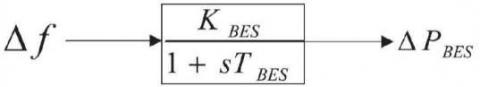
The inadequacy of a conventional frequency regulator such as DEG to regulate the frequency of dynamic load changes due to high inertia has been investigated in [58]. As a result, there is a need for a device to adjust the frequency quickly and dynamically as BESS for taking into account sudden changes in load. In Figure (5), the first-order transfer function of BESS is modeled. BESS can operate in charge or discharge mode.
Figure 5. BESS first order transfer function model
2.4 Solar power
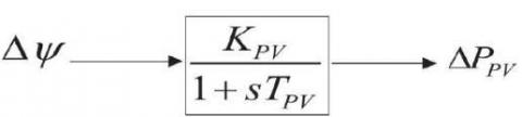
In Figure (6), the first order transfer function of solar PV power is modeled in [58].
Figure 6. Solar power first order transfer function model
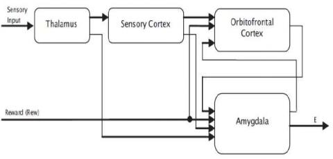
In the BELBIC method, the roots of learning include emotional factors such as emotions and anxiety. In this article, the roots of anxiety are hypothesized as stimuli. The purpose of the designed control system is to reduce the anxiety of the system caused by these stimuli. We know that the amygdala and the orbitofrontal cortex are responsible for the brain emotional learning (BEL). The inputs of the amygdaloid part are from the thalamus and the cortical areas, but in the orbital part, the inputs are only the cortical and amygdala areas. On the other hand, this part of the system receives an amplified signal (REW). Figure (7) presents a model of emotional learning in the amygdala nucleus and orbitofrontal cortex.
Figure 7. Scheme of BELBIC structure [59]
BELBIC has a number of input sensors with two different modes that can be selected by the designer. The different states of the sensors are described as (4):
$\begin{aligned} A_i & =s_i v_i \\ O_i & =s_i w_i\end{aligned}$ (4)
where, s is the input sensor, v and w are two different states that depend on the input of the sensor. Index i specifies the ith sensor and its associated state. According to [60, 61], Eq. (5) can be updated by
$\begin{gathered}\Delta v_i=\alpha s_i \max \left(0, { rew }-\sum A_i\right) \\ \Delta w_i=\beta s_i\left({ rew }-\sum A_i-\sum O_i-\max \left(s_i\right)\right)\end{gathered}$ (5)
In Eq. (5), $\alpha$ and $\beta$ are the training coefficients and rew is the reward signal. Because the orbitofrontal nucleus performs the preventive action and the amygdala acts as a stimulus, this relationship represents a BELBIC signal.
$u=\sum A_i-\sum O_i$ (6)
Because we intend to use the BELBIC continuous mode, the following equations are used to update the various BELBIC modes:
$\begin{gathered}\dot{v}_l=\alpha s_i\left({rew}-A_i\right) \\ \dot{w}_l=\beta s_i\left(r e w+s_i+O_i-A_i\right)\end{gathered}$ (7)
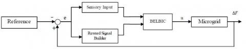
Given that the $k_{e_i}$ is constant and $e_i$ states system error, there is a design of BELBIC controller in Eq. (8) to adjust the frequency of the microgrid system. Figure (8) shows the general structure of this control structure.
$s_i=k_{e_i} e_i$ (8)
Figure 8. Control system configuration using BELBIC
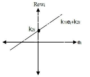
One of the signals that plays an important role in BELBIC is the reward signal. The reward function planned by the system designer must be defined in such a way that its maximum values are obtained in the most desirable areas. To achieve this result, it is better to select the reward function as a linear function of the system error. This important point is formulated in (9) so that $k_{1 i}$ and $k_{2 i}$ are positive parameters of the reward function. Figure (9) shows the reward function designed for the BELBIC controller.
${Rew}_i=k_{1 i} e_i+k_{2 i}$ (9)
Figure 9. Reward function
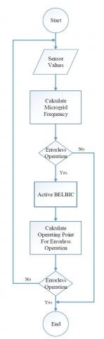
Figure 10 shows the proposed control method flowchart. After starting and obtaining the values by the sensor, the microgrid frequency is calculated. If the calculated frequency is equal to the nominal frequency of the microgrid, no action is applied by the controller, otherwise the control signal calculated by the proposed BELBIC method is applied to the microgrid system. After applying the control signal, the microgrid frequency is recalculated and the above steps are repeated.
In this section, several simulations have been performed in different time intervals on the islanded microgrid to show the proposed frequency regulator capabilities in the presence of parametric uncertainty and load disturbances. In this paper, BELBIC control method is compared with PID, optimized PID with PSO, TLBO and GWO algorithms and also the performance of the proposed control method is evaluated. Three simulation scenarios have been performed to investigate the microgrid frequency response. Table (1) presents the various parameters considered in the system.
Table 1. Parameters considered in the system
|
Wind turbine parameters |
$K_{W T G}=1, T_{W T G}=1$ |
|
Solar PV system parameters |
$K_{P V}=0.0075, T_{P V}=0.03$ |
|
BESS |
$K_{B E S}=1, T_{B E S}=0.1$ |
|
Valve Actuator |
$T_1=0.025, T_2=2, T_3=3$ |
|
Diesel Engine |
$K_E=1, T_E=3$ |
|
Speed Regulation Constant |
$R_{1,2}=5 \frac{H z}{P \cdot U \cdot M W}$ |
|
Synchronizing power coefficient |
$T_{12}=0.225$ |
|
Rotor Swing-1 |
$K_{P 1}=60, T_{P 1}=18$ |
|
Rotor Swing-2 |
$K_{P 2}=60, T_{P 2}=18$ |
Figure 10. Flowchart of the proposed control method
The controller parameters are as follows:
$k_e=1000, k_1=1, k_2=0.01, \alpha=1, \beta=-10^3$ (10)
Scenario 1: Step load disturbance
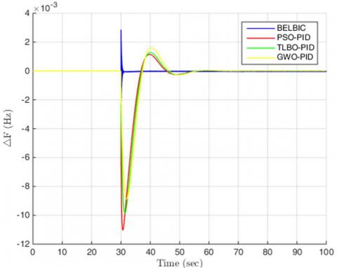
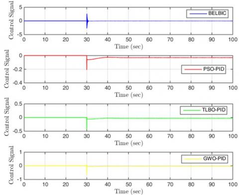
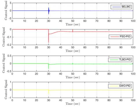
As it can be seen in Figure (11), in this scenario a load step deviation is applied to the microgrid system at t=30s. Frequency deviation and control signals are presented in Figures (12 and 13) under different control methods, respectively. As it can be seen in Figure (12), compared to PID and optimized PID, the proposed BELBIC control method is more successful in the microgrid frequency regulation. Better settling time, control and minimization of frequency deviations indicate the proper performance of the BELBIC controller. Carefully in the Figure (12), the overshoot/undershoot rate is much reduced compared to the other algorithms and the proposed controller offers a more favorable response. On the other hand, comparing the settling time of the algorithms, it can be seen that the proposed scheme offers the best settling time, and in a very short time after applying a step deviation in the load, the system reaches its steady state, and this is another important achievement of the proposed controller. This development can be examined in Figure (13). As can be seen from Figure (13), the control signal obtained from the proposed method has a non-zero value only at the moment of the load change, and after quickly adjusting of the frequency value to the nominal value, it adopts zero value.
Figure 11. Step load deviation
Figure 12. Frequency deviation of the islanded microgrid system under different controllers in scenario 1
Scenario 2: Multi-step load disturbance
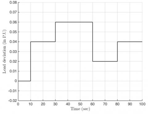
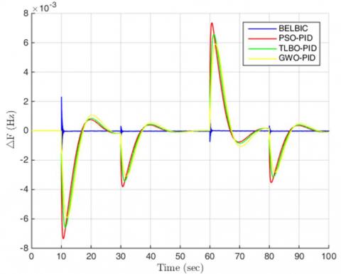
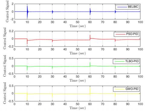
In the second scenario, in order to evaluate the proposed controller capabilities as much as possible, load disturbances are multi-stage and applied to the system in 10, 30, 60 and 80 seconds. The pattern of multiple load changes is shown in Figure (14) and the frequency deviation of an islanded microgrid based on the BELBIC controller and PID controllers are presented in Figure (15). Figure (16) shows the control signal. Low overshoot, small settling time, less control effort are some of the advantages of the proposed BELBIC control method. In this stage, as in the first scenario, for each load step deviation, the desired settling time, less time compared to other algorithms to reach a steady state, and the much less overshoot / undershoot indicate the high desirability of the proposed design. The PID methods optimized by PSO, TLBO and GWO algorithms show slower and worse behaviors in terms of transient response despite the gentle and appropriate response to load changes and also the elimination of frequency deviation.
Figure 13. Control signals obtained under different control methods in scenario 1
Figure 14. Multiple step load disturbance
Figure 15. Frequency deviation of the islanded microgrid system under different controllers in scenario 2
Figure 16. Control signals obtained under different control methods in scenario 2
Figure (16) shows the control signals obtained from the four methods used in the simulation. The Optimized PID methods, despite their low amplitude, take a non-zero value most of the time in the simulation, while the proposed BELBIC method has a non-zero value only at load change moments and is then in standby mode.
Scenario 3: Simultaneous step load disturbance and parametric uncertainty
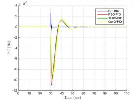
In the third scenario, at the same time as applying the parametric changes to the microgrid system according to Table (2), a load step disturbance also occurs at t = 30s. By applying step load disturbance according to Figure (11), the results of frequency deviation and control simulation are given in Figures (17 and 18), respectively. Figure (17) shows the frequency deviation and lower settling time for the BELBIC control method than other methods. As can be seen from Figure (17), the BELBIC method regulates the microgrid frequency to the nominal frequency in the shortest possible time. The optimized PID methods suffer more from high settling time as well as frequency deviation error despite their superior overshoot. The control signals obtained in this scenario also confirm the facts of the previous scenarios. The control signal from the proposed BELBIC method has the relatively large amplitude in the moments of uncertainty and disturbances, and a value of zero at other moments due to the rapid regulation of the microgrid frequency, while other methods have non-zero values in almost all moments and are not able to quickly eliminate frequency deviations. By simulating these scenarios, it can be accurately claimed that the proposed BELBIC control method offers better performance than other compared methods in terms of fluctuations, settling time, overshoot / undershoot and other characteristics.
Table 2. Parameter changes
|
No. |
Parameter |
Change% |
|
1 |
R |
+5% |
|
2 |
D |
-25% |
|
3 |
H |
+30% |
Figure 17. Frequency deviation of the islanded microgrid system under different controllers in scenario 3
Figure 18. Control signals obtained under different control methods in scenario 3
To better evaluate the performance of the proposed control method in terms of eliminating frequency deviations and zeroing the error, the amount of frequency tracking error in four methods based on different definitions of error is given in Tables 4 to 6. Tables 4 to 6 provide the error value based on the Integral square error (ISE), Integral absolute error (IAE), Integral time absolute error (ITAE) and Integral time square error (ITSE) criteria. The definition of the mentioned criteria is based on Eqs. (11) to (14), respectively:
$I S E=\int e(t)^2 \cdot d t$ (11)
$I A E=\int|e(t)| \cdot d t$ (12)
${ITAE}=\int t \cdot|e(t)| \cdot d t$ (13)
${ITSE}=\int t \cdot\left|e(t)^2\right| \cdot d t$ (14)
As can be seen from Tables 3 to 5, the best performance in terms of different error criteria is obtained by the proposed BELBIC method. After BELBIC method, in terms of ISE and ITSE errors, GWO-PID method offers better performance than PSO-PID and TLBO-PID methods. While from the point of view of IAE and ITAE errors, the PSO-PID method provides a better response than the two TLBO-PID and GWO-PID methods.
Table 3. Performance index comparison through error criteria in scenario 1
|
Controllers |
Scenario 1 |
|||
|
ISE |
ITSE |
IAE |
ITAE |
|
|
BELBIC |
2.98e-7 |
1.70e-5 |
0.0039 |
0.2848 |
|
GWO-PID |
2.66e-4 |
0.0088 |
0.0485 |
1.7048 |
|
PSO-PID |
2.95e-4 |
0.0094 |
0.0449 |
1.5288 |
|
TLBO-PID |
2.83e-4 |
0.0092 |
0.0465 |
1.6028 |
Table 4. Performance index comparison through error criteria in scenario 2
|
Controllers |
Scenario 2 |
|||
|
ISE |
ITSE |
IAE |
ITAE |
|
|
BELBIC |
2.11e-7 |
9.00e-6 |
0.0028 |
0.1515 |
|
GWO-PID |
0.0014 |
0.0650 |
0.2308 |
11.3609 |
|
PSO-PID |
0.0014 |
0.0657 |
0.2179 |
10.4347 |
|
TLBO-PID |
0.0015 |
0.0667 |
0.2237 |
10.8418 |
Table 5. Performance index comparison through error criteria in scenario 3
|
Controllers |
Scenario 3 |
|||
|
ISE |
ITSE |
IAE |
ITAE |
|
|
BELBIC |
3.43e-7 |
1.92e-5 |
0.0040 |
0.2868 |
|
GWO-PID |
2.65e-4 |
0.0087 |
0.0483 |
1.6968 |
|
PSO-PID |
2.94e-4 |
0.0094 |
0.0447 |
1.5234 |
|
TLBO-PID |
2.83e-4 |
0.0091 |
0.0463 |
1.5935 |
In this paper, BELBIC method is proposed to control the islanded microgrid frequency. According to the proposed structure, the planned technique was able to provide a rapid response for regulating the microgrid frequency, while due to changes in power generation in renewable energy sources, the presence of uncertainty parameters as well as disturbances in microgrid system load, management of nonlinear microgrid structure has become more difficult. Compared to the conventional and optimized PID controller, the simulation results indicate the better performance of the proposed method to stabilize the microgrid frequency and minimize the system frequency deviation with less settling time and lower overshoot/ undershoot. Simulations in the presence of single and multi-step disturbances as well as in the presence of parametric uncertainty showed that the proposed BELBIC control method is the fastest approach for microgrid frequency regulatory and offers the best performance from different definitions of error. Also, the control signals obtained from the simulation showed that the proposed BELBIC method is in standby mode at other times by applying the appropriate control signal at the moment of changes in the microgrid system. Considering the limitations of different parts of the microgrid system can open new research paths for the future study to develop the performance of the microgrid system.
This work was financially supported by Excellent Engineer Education and Training Plan 2.0 Professional construction Project in Jiangsu Province: Mechanical and Electronic Engineering, the priority discipline construction program of Jiangsu Province (SJYH 2022-2), First class specialty and industry education integration brand specialty in Jiangsu Province: Mechanical Design, Manufacturing and Automation (2020-9,2022-7).
[1] Li, B., Xiao, G., Lu, R., Deng, R., & Bao, H. (2019). On feasibility and limitations of detecting false data injection attacks on power grid state estimation using D-FACTS devices. IEEE Transactions on Industrial Informatics, 16(2), 854-864. https://doi.org/10.1109/TII.2019.2922215.
[2] Chen, X., Wang, T., Ying, R., & Cao, Z. (2021). A fault diagnosis method considering meteorological factors for transmission networks based on P systems. Entropy, 23(8), 1008, https://doi.org/10.3390/e23081008.
[3] Wang, T., Liu, W., Zhao, J., Guo, X., & Terzija, V. (2020). A rough set-based bio-inspired fault diagnosis method for electrical substations. International Journal of Electrical Power & Energy Systems, 119, 105961, https://doi.org/10.1016/j.ijepes.2020.105961.
[4] Wang, T., Wei, X., Wang, J., Huang, T., Peng, H., Song, X., & Perez-Jimenez, M. J. (2020). A weighted corrective fuzzy reasoning spiking neural P system for fault diagnosis in power systems with variable topologies. Engineering Applications of Artificial Intelligence, 92, 103680. https://doi.org/10.1016/j.engappai.2020.103680.
[5] Zia, M. F., Benbouzid, M., Elbouchikhi, E., Muyeen, S. M., Techato, K., & Guerrero, J. M. (2020). Microgrid transactive energy: Review, architectures, distributed ledger technologies, and market analysis. IEEE Access, 8, 19410-19432, https://doi.org/10.1109/ACCESS.2020.2968402.
[6] Zhang, L., Zheng, H., Wan, T., Shi, D., Lyu, L., & Cai, G. (2021). An integrated control algorithm of power distribution for islanded microgrid based on improved virtual synchronous generator. IET Renewable Power Generation, https://doi.org/10.1049/rpg2.12191.
[7] Jirdehi, M. A., Tabar, V. S., Ghassemzadeh, S., & Tohidi, S. (2020). Different aspects of microgrid management: A comprehensive review. Journal of Energy Storage, 30, 101457, https://doi.org/10.1016/j.est.2020.101457.
[8] R. H. Lasseter, "MicroGrids," 2002 IEEE Power Engineering Society Winter Meeting. Conference Proceedings (Cat. No.02CH37309), New York, NY, USA, 2002, pp. 305-308 vol.1, doi: 10.1109/PESW.2002.985003.
[9] R. H. Lasseter et al., "CERTS Microgrid Laboratory Test Bed," in IEEE Transactions on Power Delivery, vol. 26, no. 1, pp. 325-332, Jan. 2011, doi: 10.1109/TPWRD.2010.2051819.
[10] El-Fergany AA, El-Hameed MA. Efficient frequency controllers for autonomous two-area hybrid microgrid system using social-spider optimiser. IET Gener Transm Distrib. 2017; 11(3): 637–648, https://doi.org/10.1049/iet-gtd.2016.0455.
[11] W. Al-Saedi, S. W. Lachowicz and D. Habibi, "An optimal current control strategy for a three-phase grid- connected photovoltaic system using Particle Swarm Optimization," 2011 IEEE Power Engineering and Automation Conference, Wuhan, China, 2011, pp. 286- 290, doi: 10.1109/PEAM.2011.6134857.
[12] M.F. Roslan, M.A. Hannan, Pin Jern Ker, M.N. Uddin, Microgrid control methods toward achieving sustainable energy management, Applied Energy, Volume 240, 2019, Pages 583-607, ISSN 0306-2619, https://doi.org/10.1016/j.apenergy.2019.02.070.
[13] H. Bevrani, M. R. Feizi and S. Ataee, "Robust Frequency Control in an Islanded Microgrid: ${H} _{\infty }$ and $\mu $ -Synthesis Approaches," in IEEE Transactions on Smart Grid, vol. 7, no. 2, pp. 706-717, March 2016, doi: 10.1109/TSG.2015.2446984.
[14] Azaharahmed, M., Raja, K., Patan, M. K., Prasad, C. D., & Ganeshan, P. (2021). Invasive Weed Optimized Area Centralized 2 Degree of Freedom Combined PID Controller Scheme for Automatic Generation Control. Journal of Electrical Engineering & Technology, 16(1), 31-42, https://doi.org/10.1007/s42835-020-00565-9.
[15] Patan, M. K., Raja, K., Azaharahmed, M., Prasad, C. D., & Ganeshan, P. (2021). Influence of Primary Regulation on Frequency Control of an Isolated Microgrid Equipped with Crow Search Algorithm Tuned Classical Controllers. Journal of Electrical Engineering & Technology, 16(2), 681-695, https://doi.org/10.1007/s42835-020-00614-3.
[16] Xing, P., Ma, F., Tian, C., Xu, C., & Wang, L. (2019). Control Method of Self-Frequency Recovery and Active Power Sharing for an Isolated Microgrid Based on VSGs. Journal of Electrical Engineering & Technology, 14(1), 157-167.
[17] Bhuvnesh Khokhar, Surender Dahiya, K. P. Singh Parmar. (2021) A novel fractional order proportional integral derivative plus second-order derivative controller for load frequency control. International Journal of Sustainable Energy 40:3, pages 235-252, https://doi.org/10.1080/14786451.2020.1803861.
[18] J. M. Guerrero, P. C. Loh, T.-L. Lee, and M. Chandorkar, “Advanced control architectures for intelligent microgrids—Part II: Power quality, energy storage, and AC/DC microgrids,” IEEE Trans. Ind. Electron., vol. 60, no. 4, pp. 1263–1270, Apr. 2013, https://doi.org/10.1109/TIE.2012.2196889.
[19] J. M. Guerrero, J. C. Vasquez, J. Matas, L. G. de Vicuña, and M. Castilla, “Hierarchical control of droop- controlled AC and DC microgrids—A general approach toward standardization,” IEEE Trans. Ind. Electron., vol. 58, no. 1, pp. 158–172, Jan. 2011, https://doi.org/10.1109/TIE.2010.2066534.
[20] H. Bevrani, M. Watanabe, and Y. Mitani, “Microgrid controls,” in Standard Handbook for Electrical Engineers. New York, NY, USA: McGraw-Hill, 2012.
[21] Mallada E, Zhao C, Low S. Optimal Load-Side Control for Frequency Regulation in Smart Grids. IEEE Trans Autom Control. 2017 Dec;62(12):6294–6309, https://doi.org/10.1109/TAC.2017.2713529.
[22] D. E. Olivares et al., “Trends in microgrid control,” IEEE Trans. Smart Grid, vol. 5, no. 4, pp. 1905–1919, Jul. 2014, https://doi.org/10.1109/TSG.2013.2295514.
[23] A. H. Etemadi, E. J. Davison, and R. Iravani, “A decentralized robust control strategy for multi-DER microgrids—Part I: Fundamental concepts,” IEEE Trans. Power Del., vol. 27, no. 4, pp. 1843–1853, Oct. 2012, https://doi.org/10.1109/TPWRD.2012.2202920.
[24] Annamraju A, Nandiraju S. Robust frequency control in an autonomous microgrid: A two-stage adaptive fuzzy approach. Electr Pow Compo Sys. 2018; 46(1): 83–94, https://doi.org/10.1080/15325008.2018.1432723.
[25] Hajiakbari M, Golshan H, Esmail M. determining optimal virtual inertia and frequency control parameters to preserve the frequency stability in islanded microgrids with high penetration of renewables. Electr Power Syst Res. 2018;154:13–22, https://doi.org/10.1016/j.epsr.2017.08.007.
[26] El-Fergany AA, El-Hameed MA. Efficient frequency controllers for autonomous two-area hybrid microgrid system using social-spider optimiser. IET Gener Transm Distrib. 2017;11(3):637–648, https://doi.org/10.1049/iet-gtd.2016.0455.
[27] Bevrani H, Feizi MR, Ataee S. Robust frequency control in an islanded microgrid: H∞ and μ-Synthesis Approaches. IEEE Trans Smart Grid. 2016 March;7 (2):706–717, https://doi.org/10.1109/TSG.2015.2446984.
[28] Arefifar SA, Ordonez M, Mohamed YAI. Energy management in multi-microgrid systems—development and assessment. IEEE Trans Power Syst. 2017 March;32(2):910–922, https://doi.org/10.1109/TPWRS.2016.2568858.
[29] MiarNaeimi F, Azizyan G, Rashki M. Multi-level cross entropy optimizer (mceo): an evolutionary optimization algorithm for engineering problems. Eng Comput. 2018;34(4):719–739, https://doi.org/10.1007/s00366- 017-0569-z.
[30] Srinivasarathnam c, Chandrasekhar Yammani & Sydulu Maheswarapu (2019): Load Frequency Control of Multi- microgrid System considering Renewable Energy Sources Using Grey Wolf Optimization, Smart Science, DOI: 10.1080/23080477.2019.1630057
[31] W. Gu, W. Liu, Z. Wu, B. Zhao, and W. Chen, “Cooperative control to enhance the frequency stability of islanded microgrids with DFIG-SMES,” Energies, vol. 6, no. 8, pp. 3951–3971, 2013, https://doi.org/10.3390/en6083951.
[32] H. Bevrani, F. Habibi, P. Babahajyani, M. Watanabe, and Y. Mitani, “Intelligent frequency control in an AC microgrid: Online PSO-based fuzzy tuning approach,” IEEE Trans. Smart Grid, vol. 3, no. 4, pp. 1935–1944, Dec. 2012, https://doi.org/10.1109/TSG.2012.2196806.
[33] A. Mehrizi-Sani and R. Iravani, “Potential-function based control of a microgrid in islanded and grid- connected modes,” IEEE Trans. Power Syst., vol. 25, no. 4, pp. 1883–1891, Nov. 2010, https://doi.org/10.1109/TPWRS.2010.2045773.
[34] Q. Shafiee, J. M. Guerrero, and J. C. Vasquez, “Distributed secondary control for islanded microgrid— A novel approach,” IEEE Trans. Power Electron., vol. 29, no. 2, pp. 1018–1031, Feb. 2014, https://doi.org/10.1109/TPEL.2013.2259506.
[35] Goya T, Omine E, Kinjyo Y, et al. Frequency control in isolated island by using parallel operated battery systems applying H∞ control theory based on droop characteristics. IET Renew Power Gener. 2011;5 (2):160–166, https://doi.org/10.1049/iet-rpg.2010.0083.
[36] Lal DK, Barisal AK. Load Frequency Control of AC Microgrid Interconnected Thermal Power System. IOP Conf Ser. 2017;225:012090, DOI 10.1088/1757- 899X/225/1/012090.
[37] Dhanalakshmi R, Palaniswami S. Load frequency control of wind diesel hydro hybrid power system using conventional PI controller. Eur J Sci Res. 2011;60 (4):630–641.
[38] Vidyanandan KV, Senroy N. Frequency regulation in a wind–diesel powered microgrid using flywheels and fuel cells. IET Gener Transm Distrib. 2016;10(3):780–788, https://doi.org/10.1049/iet-gtd.2015.0449.
[39] Ray PK, Mohanty SR, Kishor N. Proportional–integral controller based small-signal analysis of hybrid distributed generation systems. Energy Convers Manage. 2011;52(4):1943–1954, https://doi.org/10.1016/j.enconman.2010.11.011.
[40] Mallesham G, Mishra S, Member S, et al. Ziegler– nichols based controller parameters tuning for load frequency control in a microgrid. Int. Conf. on Energy, Automation, and Signal; 2011 Dec 28–30, Bhubaneswar, Odisha, p. 1–8, https://doi.org/10.1109/ICEAS.2011.6147128.
[41] S. Vachirasricirikul and I. Ngamroo, “Robust controller design of microturbine and electrolyzer for frequency stabilization in a microgrid system with plug-in hybrid electric vehicles,” Elect. Power Energy Syst., vol. 43, no. 1, pp. 804–811, 2012, https://doi.org/10.1016/j.ijepes.2012.06.029.
[42] S. Vachirasricirikul and I. Ngamroo, “Robust controller design of heat pump and plug-in hybrid electric vehicle for frequency control in a smart microgrid based on specified-structure mixed H2/H∞ control technique,” Appl. Energy, vol. 88, no. 11, pp. 3860–3868, 2011, https://doi.org/10.1016/j.apenergy.2011.04.055.
[43] Gupta E, Saxena A Siew Chong Tan (Reviewing Editor). Grey wolf optimizer based regulator design for automatic generation control of interconnected power system. Cogent Eng. 2016:3(1). doi:10.1080/ 23311916.2016.1151612.
[44] Das DC, Roy AK, Sinha N. GA based frequency controller for solar thermal–diesel–wind hybrid energy generation/energy storage system. Int J Electr Power Energy Syst. 2012;43(1):262–279, https://doi.org/10.1016/j.ijepes.2012.05.025.
[45] Kumar RH, Ushakumari S. Biogeography-based Tuning of PID controllers for load frequency control in microgrid. Int. Conf. on Circuit, Power and Computing Technologies [ICCPCT]; 2014 March 20– 21 ; Nagercoil, 2014;. p. 797–802, https://doi.org/10.1109/ICCPCT.2014.7054992.
[46] Jeya Veronica A, Senthil Kumar N. Internal model based load frequency controller design for hybrid microgrid system. Energy Procedia. 2017; 117: 1032–1039, https://doi.org/10.1016/j.egypro.2017.05.225.
[47] Senjyu T, Nakaji T, Uezato K, et al. A hybrid power system using alternative energy facilities in isolated island. IEEE Trans Energy Convers. 2005 June; 20 (2): 406–414, https://doi.org/10.1109/TEC.2004.837275.
[48] B. Bequette, Wayne, Process Dynamics—Modelling, Analysis and Simulation (Prentice-Hall, Inc. Upper Saddle River, 1998)
[49] D.R. Coughnowr, Process Systems Analysis and Control (Mcgraw Hill international editions, Singapore, 1991)
[50] K.S. Narendra, K. Parthasarathy, Identification and control of dynamical systems using neural networks. IEEE Trans. Neural Netw. 1(1), 4–27 (1990), https://doi.org/10.1109/72.80202
[51] T.M. Takagi, M. Sugeno, Fuzzy identification of systems and its applications to modeling and control. IEEE Trans. Syst. Man Cybernet. 15(1), 122–132 (1985), https://doi.org/10.1109/TSMC.1985.6313399
[52] R.J. Wai, J.D. Lee, K.H. Su, Supervisory enhanced genetic algorithm control for indirect fieldoriented induction motor drive, in Proceedings IEEE International Joint Conference on Neural Networks, vol. 2, (2004), pp. 1239–1244, https://doi.org/10.1109/IJCNN.2004.1380120.
[53] M. Fatourechi, C. Lucas and A. Khakisedigh, Reducing control effort by means of emotional learning, in Proceedings of 19th Iranian Conference on Electrical Engineering, Tehran, Iran (2001), pp. 41.1–41.8
[54] C. Moren, Balkenius. Comput. Model Emotional Learn. Amygdala Cybern. Syst. 32(6), 611–636 (2000)
[55] J. Moren, Emotion and Learning—A Computational Model of the Amygdala. Ph.D dissertation, Lund University, Lund, Sweden (2002)
[56] C. Lucas, R. Mohammadi, B.N. Araabi, Intelligent modeling and control of washing machine using LLNF modeling and modified BELBIC. Asian J. Control 8(4), 393–400 (2006), https://doi.org/10.1109/ICCA.2005.1528234
[57] Kumar, A., & Srikanth, N. V. (2017). Teaching-Learning Optimization Based Adaptive Fuzzy Logic Controller for Frequency Control in an Autonomous Microgrid. International Journal of Renewable Energy Research (IJRER), 7(4), 1942-1949, https://doi.org/10.20508/ijrer.v7i4.6337.g7238.
[58] Annamraju, A., & Nandiraju, S. (2018). Robust frequency control in an autonomous microgrid: a two- stage adaptive fuzzy approach. Electric Power Components and Systems, 46(1), 83-94, https://doi.org/10.1080/15325008.2018.1432723.
[59] Lucas C, Shahmirzadi D, and Sheikholeslami N, “Introducing BELBIC: Brain emotional learning based intelligent control”, Int. J. Intell. Automat. Soft Comput. 2004; 10(1): 11–22, https://doi.org/10.1080/10798587.2004.10642862.
[60] Saeed Jafarzadeh, Rooholah Mirheidari, Mohammad Reza Jahed Motlagh, Mojtaba Barkhordari, “Designing PID and BELBIC Controllers in Path Tracking Problem”, Int. J. of Computers, Communications & Control, ISSN 1841-9836, E-ISSN 1841-9844,Vol. III (2008), Suppl. issue: Proceedings of ICCCC 2008, pp. 343-348.
[61] Saeed Jafarzadeh, Rooholah Mirheidari, Mohammad Reza Jahed Motlagh, Mojtaba Barkhordari, “Intelligent Autopilot Control Design for a 2-DOF Helicopter Model”, Int. J. of Computers, Communications & Control, ISSN 1841-9836, E-ISSN 1841-9844, Vol. III (2008), Suppl. issue: Proceedings of ICCCC 2008, pp. 337-342.