Jianhua Zhang* | Fei Song | Lingchao Zhang | Juan Wang | Changjun Liu
© 2022 IIETA. This article is published by IIETA and is licensed under the CC BY 4.0 license (http://creativecommons.org/licenses/by/4.0/).
OPEN ACCESS
Thermodynamic energy method can analyze the concrete failure, and crack emergence and propagation under hydraulic fracturing in engineering practice objectively and reasonably. The cracking of hydraulically split concrete absorbs and consumes energy, under the action of external hydraulic force and external load. The entire cracking process obeys the thermodynamic principles of energy conversion and conservation, and the principle of energy superposition. Following the thermodynamic principle of minimum energy consumption rate, this paper explores the emergence and propagation laws of concrete cracks under hydraulic fracturing. The hydraulic fracturing is essentially an energy dissipation process involving concrete failure, and crack emergence and propagation. The crack tip must feature the minimum energy consumption rate. On this basis, we proposed a new research approach for crack emergence and propagation, under the thermodynamic principle of minimum energy consumption rate. Next, we established a model for the concrete failure, and crack emergence and propagation under hydraulic fracturing. The research sheds new light on solving the dynamic hydraulic fracturing cracks induced by seismic load, and provides a reference for the seismic evaluation of super-high arch dam.
thermodynamic principle of minimum energy consumption rate, concrete, hydraulic fracturing, hydrodynamic simulation
The energy principle is the core of thermodynamic theories. Despite being an ancient discipline, thermodynamics has far-reaching influence, and strong application values. The discipline has been developing and evolving unceasingly.
Crack propagation analysis aims to determine the propagation time and propagation length of the initial damage under load [1, 2]. It is known to all that cracks change both in size and shape during the propagation. These changes add to the difficulty of crack propagation analysis [3, 4].
The common calculation methods for crack propagation include conservative estimation, shape assumption, and crack shape tracking [5-7]. Conservative estimation has gained popularity in recent years. It is a conservative engineering algorithm based on ample experiments. Shape assumption, another popular approach in recent years, usually assumes the shape of the propagating cracks, and applies the Paris’ law to at least two points on the crack front. To predict crack propagation accurately, the crack shape tracking came into being. In 1987, Teng et al. [8] tracked the non-penetrating fatigue cracks by three-dimensional (3D) finite-element method. Ibrahimbegovic et al. [9] numerically simulated the propagation of 3D fatigue cracks, using the extended finite-element method.
In essence, shape assumption and crack shape tracking are theoretically grounded on the Paris’ law. The two methods solve the crack propagation rate at the end points of the semi-axis of elliptical cracks along and perpendicular to the surface, using the formulas for the two-dimensional (2D) fatigue crack propagation rate under planar stress state and planar strain state, respectively.
The above methods are obviously successful. Based on scientific hypotheses, these methods have solid theoretical bases, and conform largely to test results. That is why they have been widely recognized and applied, which contribute greatly to the development and application of fracture mechanics. However, further research reveals some defects with these methods: the true situation of crack propagation is not reflected at the best possible accuracy. Further research is needed to develop a good crack propagation model / formula with clear physical meanings, and the ability to explain and even predict test results.
During crack propagation, the conversion of mechanical energy is accompanied by thermal phenomena. The thermal process is irreversible [10, 11]. Thus, it is necessary to study the crack propagation criterion and model, from the basic laws of thermodynamics. Based on the theory of non-equilibrium thermodynamics, this paper applies the thermodynamic principle of minimum energy consumption rate to analyze the crack emergence and propagation under hydraulic fracturing, in the light of the relationship between the principle of minimum energy consumption rate and the hydraulic fracturing of concrete (hereinafter referred to as the principle-splitting relationship), the cracking criterion based on the energy principle, and the crack propagation model.
On the theory of the constitutive relations of concrete, the macroscopic research all focuses on the thermodynamic properties of hydraulically split concrete with dissipation effect [12-15]. The purpose is to construct a unified theoretical system of constitutive relations including plasticity, viscoelasticity, and plasticity.
According to the principle of certainty, the principle of local action, and the principle of objectivity, if a variable γα=(α=1,…,k) reflecting the change of the internal structure of the material is introduced, then a general function can be established for the k internal variables:
$\left\{\begin{array}{l}W=W\left(\varepsilon, T, g, \gamma_{1}, \ldots, \gamma_{k}\right) \\ \sigma=\sigma\left(\varepsilon, T, g, \gamma_{1}, \ldots, \gamma_{k}\right) \\ S=S\left(\varepsilon, T, g, \gamma_{1}, \ldots, \gamma_{k}\right) \\ q=q\left(\varepsilon, T, D, \varepsilon^{N}, \gamma_{1}, \ldots, \gamma_{k}\right) \\ \gamma_{1}=f_{1}\left(\varepsilon, T, D, \varepsilon^{N}, \gamma_{1}, \ldots, \gamma_{k}\right) \\ \quad \vdots \\ \gamma_{k}=f_{k}\left(\varepsilon, T, D, \varepsilon^{N}, \gamma_{1}, \ldots, \gamma_{k}\right)\end{array}\right.$ (1)
where, W, σ, S and q are the free energy, generalized stress, entropy, and heat flux of hydraulically split concrete, respectively; D is the damage variable; ε, εN, T and g are the generalized strain, inelastic strain, temperature, and temperature gradient of hydraulically split concrete, respectively; γ1,…,γk are the k internal variables.
To determine the constitutive relations of a material, the premise is that these relations do not contradict universal laws of nature, such as the law of conservation of energy, the law of conservation of momentum, and the second law of thermodynamics.
The law of conservation of energy:
$\frac{1}{\rho_{0}} \operatorname{tr}(\sigma \dot{\varepsilon})-\frac{1}{\rho_{0}} \nabla x \cdot q+r=\dot{W}+T \dot{S}+\dot{T} S$ (2a)
The law of conservation of momentum
$\frac{1}{\rho_{0}} \nabla x \cdot(F \sigma)+b=\ddot{x}$ (2b)
The second law of thermodynamics:
$-\dot{W}-\dot{T} S+\frac{1}{\rho_{0}} \operatorname{tr}(\sigma \dot{\varepsilon})-\frac{1}{\rho_{0} T} q \cdot g \geq 0$ (2c)
where, ρ0 is the density of the material; b is the force vector; r is the external heat provided to a unit of mass per unit time; x is the spatial coordinates; F=∂x/∂X and g=∂T/∂X are deformation gradient and temperature gradient, respectively. The first three parameters are often known.
Taking the derivative of the first line in formula (1):
$\dot{W}=\operatorname{tr}\left(\frac{\partial W}{\partial \varepsilon} \dot{\varepsilon}\right)+\frac{\partial W}{\partial T} \dot{T}+\frac{\partial W}{\partial g} \cdot \dot{g}+\sum_{i=1}^{k} \frac{\partial W}{\partial \gamma_{i}} \dot{\gamma}_{i}$ (3)
Substituting formula (3) into formula (2-c):
$\frac{1}{\rho_{0}} \operatorname{tr}\left\{\left(\sigma-\rho_{0} \frac{\partial W}{\partial \varepsilon}\right) \dot{\varepsilon}\right\}-\left(S+\frac{\partial W}{\partial T}\right) \dot{T}$$-\frac{\partial W}{\partial g} \cdot \dot{g}-\frac{\partial W}{\partial \gamma_{i}} \dot{\gamma}_{i}-\frac{1}{\rho_{0} T} q \cdot g \geq 0$ (4)
In formula (4), $\dot{\varepsilon}, \dot{T}$, and $\dot{g}$ can be chosen arbitrarily. Thus:
$\frac{\partial W}{\partial g}=0, \sigma-\rho_{0} \frac{\partial W}{\partial \varepsilon}=0, S+\frac{\partial W}{\partial T}=0$ (5)
By formula (5), the constitutive relations expressed by formula (1) can be transformed into:
$\left\{\begin{array}{l}W=W\left(\varepsilon, T, D, \varepsilon^{N}, \gamma_{1}, \ldots, \gamma_{k}\right) \\ \sigma=\rho_{0} \frac{\partial W}{\partial \varepsilon} \\ S=-\frac{\partial W}{\partial T} \\ q=q\left(\varepsilon, T, D, \varepsilon^{N}, \gamma_{1}, \ldots, \gamma_{k}\right) \\ \dot{\gamma}_{1}=f_{1}\left(\varepsilon, T, D, \varepsilon^{N}, \gamma_{1}, \ldots, \gamma_{k}\right) \\ \vdots \\ \dot{\gamma}_{k}=f_{k}\left(\varepsilon, T, D, \varepsilon^{N}, \gamma_{1}, \ldots, \gamma_{k}\right)\end{array}\right.$ (6)
For hydraulically split concrete, the simple constitutive relations (6) were obtained by introducing the k internal variables γα=(α=1,⋯,k), reflecting the energy consumption mechanism of the concrete. It can be seen from formula (6) that the key to building the dissipative constitutive relations is to determine the expression of q and the evolution equations of all internal variables.
Similar to the yielding and failure of materials, crack propagation consumes energy. Thus, the energy consumed by propagating cracks is constrained by the principle of minimum energy consumption rate. In other words, the energy consumption of crack propagation must be the minimal under the corresponding constraints [16]. If this view is introduced to the theoretical analysis on crack propagation, any form of damage is an energy consumption process, and ought to obey the principle of minimum energy consumption rate. Following this train of thought, the obtained criterion can reflect the influence of concrete performance, and the effects of the stress or strain inducing material failure. To sum up, the design of cracking criterion, a thorny issue in mechanics, can be realized more realistically under the unified framework of the principle of minimum energy consumption rate.
According to damage mechanics, when the external load is applied without changing the boundary conditions, if the damage variable at a point satisfies $D<1$, the nominal stress $\sigma_{i j}$ corresponding to the load at the point remains the same, while the effect stress $\tilde{\sigma}_{i j}=\frac{\sigma_{i j}}{1-D}$ at the point increases with D. The nominal stress $\sigma_{i j}$ only changes, if the nominal stress is redistributed after macroscopic damages. In addition, an irreversible strain $\dot{\varepsilon}_{i}^{N}$ will occur at the point, during the energy consumption process prior to complete failure (hereinafter referred to the damage process). Without considering other energy consumption factors, $\dot{\varepsilon}_{i}^{N}$ can be regarded as the only energy consumption mechanism during the damage process. In this process, the energy consumption rate at any point near the crack tip at any time $t$ can be calculated by:
$\varphi(t)=\sigma_{i j}(r, \theta) \dot{\varepsilon}_{i j}^{N}\left[\sigma_{i j}(r, \theta), a_{i}(t)\right]$ (7)
where, $t$ is the time parameter of the damage process at the point; $r$ and $\theta$ are the polar coordinates with the crack tip as the origin; $a_{i}(t)(i=1, \cdots, n)$ is the time-varying material parameter; $\sigma_{j j}(r, \theta)$ is the nominal stress tensor at point $(r, \theta)$ near crack tip; $\dot{\varepsilon}_{i j}^{N}\left[\sigma_{i j}(r, \theta), a_{i}(t)\right]$ is the irreversible strain rate tensor at point $(r, \theta)$ at time t. During the damage process, $\dot{\varepsilon}_{i j}^{N}\left[\sigma_{i j}(r, \theta), a_{i}(t)\right]$ is related to the nominal stress tensor $\sigma_{i j}(r, \theta)$ at the point and $a_{i}(t)$.
Moreover, the damage process at the point $(r, \theta)$ near the crack tip, as shown by formula (7), should satisfy the following constraints: (1) The nominal stress tensor $\sigma_{i j}(r, \theta)$ depends on the expression of the stress field near the crack tip; under a given load, the nominal stress $\sigma_{i j}(r, \theta)$ corresponding to the load will remain constant, as long as the crack does not propagation; (2) The relationship between irreversible strain rate tensor $\dot{\varepsilon}_{i j}^{N}\left[\sigma_{i j}(r, \theta), a_{i}(t)\right] \sigma_{i j}(r, \theta)$, and $a_{i}(t)$ should meet the relationship between stress and strain rate of the material during the damage process.
According to the principle of minimum energy consumption rate, only the point, where formula (7) is minimized under the above two constraints, falls on the crack propagation path. Substituting the two constraints to formula (7), we have $\varphi(t)=\varphi\left[r, \theta, a_{i}(t)\right]$. Thus, the direction $\theta_{\min }$ of the minimum energy consumption rate for the damage process, when $r$ is fixed at a small value approximating zero, can be determined by:
$\left\{\begin{array}{l}\frac{\partial \varphi\left[r, \theta, a_{i}(t)\right]}{\partial \theta}=0 \\ \frac{\partial^{2} \varphi\left[r, \theta, a_{i}(t)\right]}{\partial \theta^{2}}>0\end{array}\right.$ (8)
Thus, the crack emergence criterion can be obtained:
$\left.\varphi_{\min }(t)\right|_{t=0}=\left.\varphi\left[r, \theta_{\min }, a_{i}(t)\right]\right|_{t=0}=\left.\varphi_{c}(t)\right|_{t=0}$ (9)
The physical meaning of formula (9) is as follows: The crack emerges, when $r$ is fixed at a small value approximating zero, and the energy consumption rate $\left.\varphi_{\min }\right|_{t=0} \mid$ at the minimum direction $\theta_{\text {min }}$ reaches the crack emergence threshold $\left.\varphi_{c}(t)\right|_{t=0}$.
Crack propagation has a complex mechanical mechanism. The existing mechanical models cannot objectively describe the whole process of crack propagation.
Similar to crack emergence, the propagation of split concrete cracks needs to consume energy. The energy consumption of crack propagation also needs to obey the principle of minimum energy consumption rate. This sheds new light on the establishment of crack propagation criterion and model.
Crack propagation analysis aims to determine the propagation time and propagation length of the initial damage under load. It is known to all that cracks change both in size and shape during the propagation [17-19]. These changes add to the difficulty of crack propagation analysis.
There are three common theories for calculating the direction of crack propagation [20, 21]:
(1) Maximum tensile stress theory:
The initial propagation direction of the crack points to the maximum circumferential normal stress. The crack propagation occurs when the maximum circumferential normal stress in the direction reaches the critical value.
(2) Theory of minimum strain energy density factor:
The crack starts to expand along the direction with the smallest strain energy density factor. The crack propagation occurs when the minimum strain energy density factor reaches the critical value of concrete.
(3) Theory of energy release rate:
The crack propagates in the direction of the maximum energy release rate. The crack propagation occurs when the maximum energy release rate reaches the critical value.
A comprehensive comparison of the above three theories shows that the energy release rate (G criterion) has the clearest physical meaning, but requires complex calculations. The major difference between compound crack propagation and the classical Griffith propagation is that the crack no longer propagates along the original crack surface, but along new branches. To solve the problem of new propagation directions, it is necessary to compute the strain energy release rate in each direction. Since the crack initiation angle θ is unknown, the general practice is to conformally transform such a broken line crack with an arbitrary angle into a unit circle. Thus, a complex function needs to be introduced, and the integral equation of the function needs to be derived. All these operations complicate the calculation. To avoid the tedious calculation, some researchers simply assume that the composite crack still propagates in the original direction. But the assumption is far from the reality.
The $\sigma_{\theta \max }$ criterion is simple to compute, and clear in physical meaning. However, the crack initiation angle is determined, without considering the property of hydraulically split concrete.
The S criterion makes up this defect by combining the critical condition of crack propagation with the performance of hydraulically split concrete. This criterion applies to a wide range of problems, and requires simple calculation. The problem of this criterion lies in the lack of clear physical meaning. There are different understandings concerning why the predicted crack propagation direction is consistent with the direction of the minimum strain energy density factor [18].
The common point of G criterion and S criterion is that both consider the mechanical quantities on the concentric circles with the crack tip as the center. Although the points on these concentric circles have obvious geometric meaning (equal dimensions from the crack tip), they are not under the same stress state. Therefore, the mechanical meaning is unclear by simply comparing the mechanical quantities at these points.
In this paper, the thermodynamic law of energy conservation, the theory of entropy change, and the energy difference rate method of fracture mechanics are integrated to explore the crack propagation law, establish crack propagation criterion, and build crack propagation model.
For a unit volume of hydraulically split concrete, the energy conservation equation can be obtained according to the first law of thermodynamics:
$\frac{d E}{d t}=\int_{V} \frac{d R}{d t} d V-\int_{A} Q_{i} n_{i} d A+\sum_{i=1}^{M} P_{i} d u_{i}$ (10)
where, $E$ is the absolute thermodynamic temperature; $\mathrm{R}$ is plastic strain energy per unit volume of hydraulically split concrete; $Q_{i}=U_{b}+\Pi_{w}$ is the heat loss induced by the energy absorption by the proppant and the leaching of the fracturing fluid per unit area in a unit time; $P_{i}$ is the generalized external forces working on hydraulically split concrete; $u_{i}$ is the generalized displacement of the deformation of hydraulically split concrete; $\mathrm{M}$ is the number of generalized external forces.
The crack propagation is an irreversible process. According to the thermodynamic definition of medium entropy, when the temperature field is uniform, the change rate of the entropy S of cracked elastic concrete with time can be calculated by:
$\frac{d S}{d t}=\frac{1}{T} \int_{V} \frac{d R}{d t} d V-\frac{1}{T} \int_{A} Q_{i} n_{i} d A$$+\frac{1}{T} \sum_{i=1}^{2} G_{i} \frac{d a_{i}}{d t}$ (11)
where, T is the absolute thermodynamic temperature; Gi is the driving energy of crack propagation; ai is the size of the expanding crack.
In thermodynamics, Helmholtz free energy W is a function that characterizes the state variables of the system in the thermodynamic process. The energy can be expressed as the internal energy E of the system minus the product of its absolute temperature T and entropy S:
$W=E-T S$ (12)
Taking the time derivatives on both sides of formula (12):
$\frac{d W}{d t}=\frac{d E}{d t}-T \frac{d S}{d t}-S \frac{d T}{d t}$ (13)
Substituting formulas (10) and (11) into formula (13):
$\frac{d W}{d t}=\sum_{i=1}^{M} P_{i} \frac{d u_{i}}{d t}-\sum_{i=1}^{2} G_{i} \frac{d a_{i}}{d t}-S \frac{d T}{d t}$ (14)
Obviously, formula (14) is a complete differential equation.
Hence, the free energy W is a function of state variables ui, ai and T:
$W=W\left(u_{1}, \mathrm{~L}, u_{M}, T, a_{1}, a_{2}\right)$ (15)
Formula (14) can be rewritten as:
$\frac{d W}{d t}=\sum_{i=1}^{M} \frac{\partial W}{\partial u_{i}} \frac{d u_{i}}{d t}+\sum_{i=1}^{2} \frac{\partial W}{\partial a_{i}} \frac{d a_{i}}{d t}+\frac{\partial W}{\partial T} \frac{d T}{d t}$ (16)
Comparing formulas (16) and (14), the following relations can be derived in the light of the independence of the state variables in the free energy:
$P_{i}=\frac{\partial W}{\partial u_{i}}$ (17)
$G_{i}=\frac{\partial W}{\partial a_{i}}$ (18)
$S=\frac{\partial W}{\partial T}$ (19)
In general, if the hydraulic fracturing load rate is small, the crack propagates slowly. Then, the crack propagation can be approximately regarded as an isothermal process. Therefore, there exists $\frac{d T}{d t}=0$. Hence, formula (14) can be rewritten as:
$\frac{d W}{d t}=\sum_{i=1}^{M} P_{i} \frac{d u_{i}}{d t}-\sum_{i=1}^{2} G_{i} \frac{d a_{i}}{d t}$ (20)
Correspondingly, in the isothermal process, the free energy $\mathrm{W}$ is a function of state variables $u_{i}$ and $a_{i}$, and equal to the strain energy U:
$W=U\left(u_{1}, \mathrm{~L}, u_{M}, a_{1}, a_{2}\right)$ (21)
If the cracked elastic concrete belongs to a uniform temperature field, the following can be derived from the second law of thermodynamics:
$\frac{d S}{d t} \geq \frac{1}{T} \int_{V} \frac{d R}{d t} d V-\frac{1}{T} \int_{A} Q_{i} n_{i} d A$ (22)
Combined with formula (11), formula (14) can be rewritten as:
$\sum_{i=1}^{2} G_{i} \frac{d a_{i}}{d t} \geq 0$ (23)
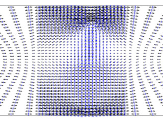
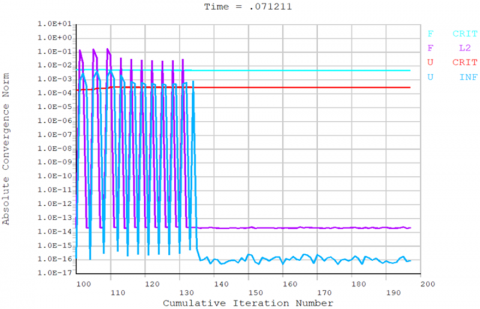
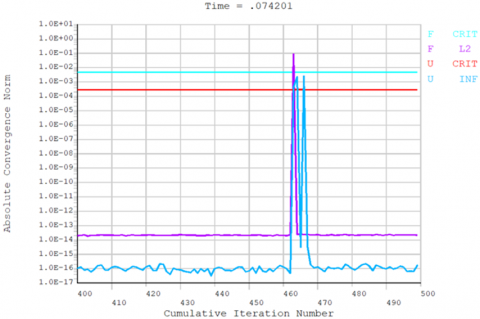
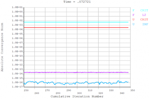
Focusing on the hydrodynamic cracking of concrete in super-high arch dam, we compiled the solution program in MATLAB language according to the principle of minimum energy consumption rate, and simulated the propagation of hydraulically split cracks in concrete, using the post-processing function of ANSYS, and the APDL language. The simulation results are presented in Figures 1-4.
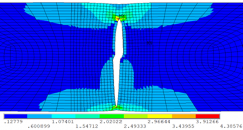
(a) Grid meshing (densified in central crack zone)
(b) Node vectograph;
(c) Unit vectograph
Figure 1. Finite-element model
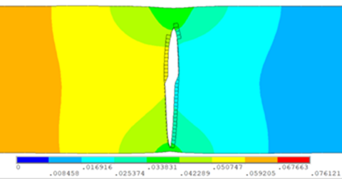
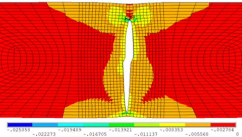
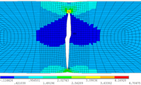
Figure 2. Iterations under different loads
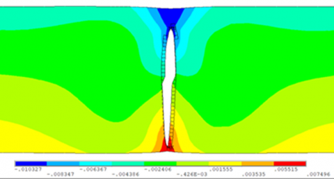
Figure 3. Results under different directions
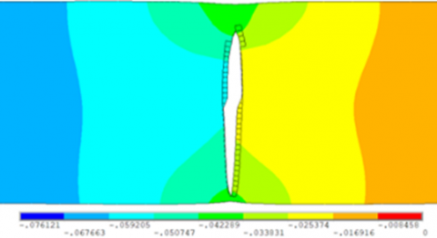
Figure 4. Results on different units
The cracking process was basically consistent with the experimental results in the literature, which verifies the validity of our method and theory. During the simulation, both hydraulic pressure and seismic stress were applied. The following conclusion was drawn from the simulation results: When a constant hydraulic pressure was applied in the axial direction, microcracks appeared in defected areas, and the water infiltrated the concrete. Further application of the seismic acceleration power spectral density would speed up the damage of the specimen along the cracks.
Crack propagation is an energy consumption process. The energy consumed by the propagating cracks obeys the principle of minimum energy consumption rate. In other words, the energy consumption of crack propagation must be the minimal under the corresponding constraints. From the angle of energy distribution, the above view was inherited to open a new way for setting up the criterion of crack propagation, and disclose the energy change law of the propagation process. From the first law of thermodynamics, we derived the energy conservation equation for crack propagation, established the thermodynamic law expression for cracked concrete, and then constructed the driving energy expression of crack propagation. On this basis, a crack propagation criterion was developed, represented by the driving energy. Under the criterion, a visual simulation was carried out through hybrid programming, which verifies the validity of our theory.
This paper was endowed by Water Conservancy Science and Technology Plan Project of Shaanxi Province (Grant No.: 2019slkj-19).
[1] Liang, X. (2020). On the crack evolution and failure form of concrete specimens based on minimum energy principle. Multimedia Tools and Applications, 79(15): 10629-10638. https://doi.org/10.1007/s11042-019-7616-2
[2] Liu, Y.F., Cho, S., Spencer Jr, B.F., Fan, J.S. (2016). Concrete crack assessment using digital image processing and 3D scene reconstruction. Journal of Computing in Civil Engineering, 30(1): 04014124. https://doi.org/10.1061/(ASCE)CP.1943-5487.0000446
[3] Saliba, J., Matallah, M., Loukili, A., Regoin, J.P., Grégoire, D., Verdon, L., Pijaudier-Cabot, G. (2016). Experimental and numerical analysis of crack evolution in concrete through acoustic emission technique and mesoscale modelling. Engineering Fracture Mechanics, 167: 123-137. https://doi.org/10.1016/j.engfracmech.2016.03.044
[4] Dias, I.F., Oliver, J., Lemos, J.V., Lloberas-Valls, O. (2016). Modeling tensile crack propagation in concrete gravity dams via crack-path-field and strain injection techniques. Engineering Fracture Mechanics, 154: 288-310. https://doi.org/10.1016/j.engfracmech.2015.12.028
[5] Shi, T., Leung, C.K. (2017). Minimum energy based method to predict the multiple cracking pattern in quasi-brittle beam. International Journal of Solids and Structures, 117: 1-13. https://doi.org/10.1016/j.ijsolstr.2017.04.019
[6] Frosch, R.J. (1999). Another look at cracking and crack control in reinforced concrete. Structural Journal, 96(3): 437-442.
[7] Roth, S.N., Léger, P., Soulaïmani, A. (2020). Strongly coupled XFEM formulation for non-planar three-dimensional simulation of hydraulic fracturing with emphasis on concrete dams. Computer Methods in Applied Mechanics and Engineering, 363: 112899. https://doi.org/10.1016/j.cma.2020.112899
[8] Teng, C.K., Yin, X.C., Li, S.Y. (1987). An experimental investigation on 3D fractures of non-penetrating crack in plane samples. Acta Geophys Sin, 30(4): 371-378.
[9] Ibrahimbegovic, A., Boulkertous, A., Davenne, L., Brancherie, D. (2010). Modelling of reinforced‐concrete structures providing crack‐spacing based on X‐FEM, ED‐FEM and novel operator split solution procedure. International Journal for Numerical Methods in Engineering, 83(4): 452-481. https://doi.org/10.1002/nme.2838
[10] Farrahi, G.H., Javanbakht, M., Jafarzadeh, H. (2020). On the phase field modeling of crack growth and analytical treatment on the parameters. Continuum Mechanics and Thermodynamics, 32(3): 589-606. https://doi.org/10.1007/s00161-018-0685
[11] Brünig, M., Michalski, A. (2017). A stress-state-dependent continuum damage model for concrete based on irreversible thermodynamics. International Journal of Plasticity, 90: 31-43. https://doi.org/10.1016/j.ijplas.2016.12.002
[12] Onifade, I. (2017). Development of energy-based damage and plasticity models for asphalt concrete mixtures. Doctoral Dissertation, KTH Royal Institute of Technology.
[13] Andreaus, U., Casini, P. (2016). Identification of multiple open and fatigue cracks in beam-like structures using wavelets on deflection signals. Continuum Mechanics and Thermodynamics, 28(1): 361-378. https://doi.org/10.1007/s00161-015-0435-4
[14] Kazemi, A., Baghani, M., Shahsavari, H., Abrinia, K., Baniassadi, M. (2017). Application of elastic-damage-heal model for self-healing concrete thick-walled cylinders through thermodynamics of irreversible processes. International Journal of Applied Mechanics, 9(6): 1750082. https://doi.org/10.1142/S175882511750082X
[15] Xu, B., Lei, X., Wang, P., Song, H. (2021). A strain rate-dependent damage evolution model for concrete based on experimental results. Advances in Civil Engineering, 2021. https://doi.org/10.1155/2021/6643263
[16] Baktheer, A., Chudoba, R. (2019). Classification and evaluation of phenomenological numerical models for concrete fatigue behavior under compression. Construction and Building Materials, 221: 661-677. https://doi.org/10.1016/j.conbuildmat.2019.06.022
[17] Li, J., Li, L., Li, L. (2019). Analysis of chloride ion diffusion in concrete structure under non-penetrating crack condition. Journal of Tongji University (Natural Science).
[18] Anderssohn, R., Hofmann, M., Bahr, H.A. (2018). FEM-bifurcation analysis for 3D crack patterns. Engineering Fracture Mechanics, 202: 363-374. https://doi.org/10.1016/j.engfracmech.2018.07.040
[19] Quaranta, L., Maddegedara, L., Okinaka, T., Hori, M. (2020). Application of PDS–FEM to simulate dynamic crack propagation and supershear rupture. Computational Mechanics, 65(5): 1289-1304. https://doi.org/10.1007/s00466-020-01819-z
[20] Villa, V., Singh, R.P. (2020). Hydraulic fracturing operation for oil and gas production and associated earthquake activities across the USA. Environmental Earth Sciences, 79(11): 1-11. https://doi.org/10.1007/s12665-020-09008-0
[21] Igonin, N., Zecevic, M., Eaton, D.W. (2018). Bilinear magnitude‐frequency distributions and characteristic earthquakes during hydraulic fracturing. Geophysical Research Letters, 45(23): 12-866. https://doi.org/10.1029/2018GL079746