
Abbas H. Abdulabbas* | Suhad M. Abd | Afnan H. Ali | Asmaa Shaker Mahmood | Murtada A. Ismeal
© 2026 The authors. This article is published by IIETA and is licensed under the CC BY 4.0 license (http://creativecommons.org/licenses/by/4.0/).
OPEN ACCESS
This paper investigates the effect of concrete confinement using a polyvinyl chloride (PVC) tube and the strengthening of this confinement with single, two, and three layers of carbon textile-reinforced concrete (CTRC). Forty-five samples were studied and divided into three diameter groups (100, 150, and 200 mm). Each group was further divided into three subgroups based on length. The study examined unconfined concrete, PVC-tube-confined concrete, and CTRC-strengthened concrete. The results indicate an increase in the peak load capacity of the PVC-confined samples from 29% to 64.2% compared to the unconfined samples for each subgroup, while the increase in the peak load capacity of the CTRC-strengthened samples was from 79% to 131.2% compared to the unconfined samples for each subgroup. The peak load of the CTRC-strengthened samples increased from 9.2% to 65.56% compared to the confined samples for each subgroup. These findings demonstrated that the PVC tube confinement and CTRC strengthening enhance the resistance of the samples to the axial compressive strength of the concrete. This effect depends on the thickness of the PVC tube and the diameter of the samples, with pipe thickness having a significant impact and diameter having a particularly pronounced effect, especially when the length-to-diameter ratio is less than or equal to 2.
carbon textile-reinforced concrete, polyvinyl chloride tubes, concrete, confinement, strengthening
To improve the properties of concrete, it is common to combine it with various materials to enhance its characteristics and durability. Traditionally, steel tubes have been used to reinforce concrete due to their strength and rigidity. When steel tubes are used and filled with concrete, these two elements combine the compressive strength of concrete with the tensile strength of steel, offering a wide range of applications in buildings, including long-span bridges and high-rise buildings [1, 2]. On the other hand, steel tubes incur high construction and maintenance costs and are susceptible to corrosion under harsh environmental conditions [3, 4]. Therefore, alternatives to steel tubes, including fiber-reinforced polymer (FRP) tubes, were used. While FRP tube is highly corrosion-resistant, its construction costs and brittleness limit its suitability for certain construction applications [5-9]. Conversely, polyvinyl chloride (PVC) tube is a superior alternative to steel and FRP tube because of its unique properties: a blend of polymer resins, stabilizers, and pigments, along with the ability to customize it to meet specific requirements [10, 11]. PVC is a universal option that outperforms other alternatives economically and is suitable for various infrastructure projects at different scales [12]. Polymer materials are widely used due to their exceptional properties, and these materials include tubes used for water supply and drainage, as well as materials used in the construction of cables and wires [13-15]. The construction sector has extensively exploited the properties of polymers in construction processes [16-26]. In many civil engineering applications, concrete-filled tubular columns are used because of their excellent seismic performance, characterized by high resistance to axial compression and stiffness [27]. These tubes delay the lateral expansion of the concrete and provide support to the tube to resist buckling by surrounding its outer core [28]. Confining the concrete within the tube places it under triaxial stress, thereby improving the pipe’s compressive strength [29, 30]. From a sustainability perspective, using tubes eliminates the need for formwork, as the tubes used are recycled, reducing construction costs and time [31].
Therefore, the demand for and use of these types of columns has increased due to their ease of construction [32]. Concrete-filled plastic tubes are a promising option in the field, offering an excellent alternative to steel columns for their superior durability [33]. PVC tubes have many features that qualify them for use as concrete columns, including their light weight, minimal need for maintenance, ease of manufacturing from recycled materials, which provides economical construction, excellent corrosion resistance, and, similarly, their resistance to chemicals, to which they have very high resistance [34]. Recent studies have addressed the use of PVC tubes to reinforce concrete, including [35]: Askari et al. investigated the behavior of unconfined and confined columns using unplasticized polyvinyl chloride (uPVC) tube reinforced with polypropylene fibers. Several parameters, including sample sizes, compressive strength, pipe type, and polypropylene fiber content in the concrete mix [36]. Woldemariam et al. evaluated confinement of concrete using a uPVC tube by studying several variables, including pipe wall thickness, concrete compressive strength, and length-to-diameter ratio (L/D) [37]. Hammadi et al. examined the effectiveness of full and partial confinement using PVC tube with varying pipe diameters, and the effect of changing the height-to-diameter ratio was investigated [38]. Chena et al. studied the strengthening of previously damaged columns with carbon fiber. The study focused on two factors: the degree of damage to the columns and the type of material used for strengthening, including engineered cementitious composite (ECC) in addition to polymer fabric, strengthening using carbon fibers embedded in textile-reinforced ECC (TRE), and strengthening using carbon fibers embedded in cement mortar textile-reinforced mortar (TRM) as a comparative sample [39]. Ling and Chin [39] examined the effect of concrete type on tube behavior by using plain concrete and glass-fiber-reinforced concrete (GFRC). It also investigated the effect of varying sample diameters (from 75 mm to 150 mm) and fiber content (from 0 to 0.15% of cement weight). Regarding confinement, the study considered both the use of PVC tubes and the absence of PVC tubes for the same parameters.
From this perspective, a deficiency was observed in some variables and types of strengthening that can be applied to PVC concrete-filled tubes. This study aims to bridge this gap by using a new strengthening method: Carbon textile-reinforced concrete (CTRC). It also investigates the effects of confinement and non-confinement, as well as the impact of variations in diameter, height, thickness of the PVC tube, and the number of CTRC layers for each case. CTRC technology relies on an inorganic cementitious binder (which offers fire resistance and durability compared to polymeric materials), unlike conventional carbon fiber-reinforced polymer (CFRP) technology, which utilizes organic polymer resins.
This section will briefly present the experimental program of the study, construction materials used in preparing concrete samples, culminating in the required tests for PVC tube concrete.
2.1 The program of the experimental work
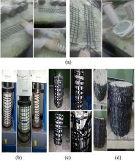
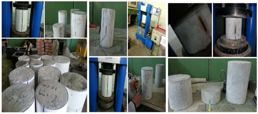
Forty-five cylindrical specimens (each specimen is an average of three tests) were created and divided into three groups according to diameter (100 mm, 150 mm, and 200 mm). Each group (each diameter separately) was further divided into three subgroups based on length (100 mm, 200 mm, and 300 mm). Each subgroup contains one specimen inside a PVC tube and three specimens surrounded by a PVC tube and strengthened with CTRC. There is also a reference specimen without PVC and CTRC for all specimens for comparison. Thus, the total number of specimens is 5 per subgroup, which investigates the effect of diameter and length on the behavior of the cylinders, which are considered variables in this study, in addition to thickness, as shown in Table 1. After preparing the molds, the PVC tubes were made to the required diameter and length. The fresh concrete was then placed inside a PVC tube for casting. A vibrating table was used for a few minutes to prevent clumping and expel air from the voids, as illustrated in Figure 1. Twenty-four hours after the casting process, all specimens were immersed in water for 28 days to harden. After hardening, the specimens were removed from the water and left to dry. The molds were then coated with CTRC, which was wrapped around PVC tubes using epoxy at a ratio of 1:4, as shown in Figure 2. They were left for 24 hours in the laboratory to be ready for testing using a compression testing device, as shown in Figure 3.
Figure 1. Model preparation stages
Figure 2. Preparation of a specimen with carbon textile-reinforced concrete (CTRC): (a) CTRC with epoxy, (b) specimen with one layer, (c) specimen with two layers, and (d) specimen with three layers
Figure 3. The curing and testing of the specimens
2.2 Raw materials properties
2.2.1 Cement
The cement is used as the primary binder for all concrete mixtures, ordinary Portland cement (OPC) Type 1. The physical and chemical requirements conform to the Iraqi Standard No. 5. 1984 [40].
2.2.2 Fine aggregate
In this investigation, local Iraqi sand was taken from the Al-Sidr Suburb in the Diyala Governorate with properties governed by the Iraqi Specification No. 45, 1984 [41]. Utilized as a fine aggregate after sieving and washing with clean water to remove all organic impurities, silt, and clay to ensure the production of high-quality concrete.
2.2.3 Coarse aggregate
10 mm maximum size aggregate was used as a coarse aggregate for the concrete mixtures. It was obtained from the Al-Sider Suburb, an Iraqi city, with the characteristics according to the second version of the Iraqi Specifications No. 45, 1984 [41].
2.2.4 Mixing water
The conventional tap water was employed throughout the experimental program for the mixing and the subsequent curing processes.
2.2.5 Polyvinyl chloride tubes
This study used PVC tubes, which are among the most common types in Iraq. They were used in various diameters and lengths, divided into three groups as shown in Table 1, where Table 2 shows the properties of PVC tubes.
Table 1. Characteristics of cylinder concrete
|
Diameter (D) (mm) |
Length (L) (mm) |
Thickness (t ((mm) |
L/D |
ID Specimen |
Type of Confinement |
|
100 |
100 |
|
|
D1L1-1 |
Without |
|
|
|
D1L1-2 |
Confinement With PVC |
||
|
2.5 |
1 |
D1L1-3 |
PVC + 1Layer CTRC |
||
|
|
|
D1L1-4 |
PVC + 2Layer CTRC |
||
|
|
|
D1L1-5 |
PVC + 3Layer CTRC |
||
|
200 |
|
|
D1L2-1 |
Without |
|
|
2.5 |
|
D1L2-2 |
Confinement With PVC |
||
|
|
2 |
D1L2-3 |
PVC + 1Layer CTRC |
||
|
|
|
D1L2-4 |
PVC + 2Layer CTRC |
||
|
|
|
D1L2-5 |
PVC + 3Layer CTRC |
||
|
300 |
|
|
D1L3-1 |
Without |
|
|
|
|
D1L3-2 |
confinement with PVC |
||
|
2.5 |
3 |
D1L3-3 |
PVC + 1Layer CTRC |
||
|
|
|
D1L3-4 |
PVC + 2Layer CTRC |
||
|
|
|
D1L3-5 |
PVC + 3Layer CTRC |
||
|
150 |
100 |
|
|
D2L1-1 |
Without |
|
|
|
D2L1-2 |
Confinement With PVC |
||
|
3 |
0.67 |
D2L1-3 |
PVC + 1Layer CTRC |
||
|
|
|
D2L1-4 |
PVC + 2Layer CTRC |
||
|
|
|
D2L1-5 |
PVC + 3Layer CTRC |
||
|
200 |
|
1.33 |
D2L2-1 |
Without |
|
|
|
D2L2-2 |
Confinement With PVC |
|||
|
3 |
D2L2-3 |
PVC + 1Layer CTRC |
|||
|
|
D2L2-4 |
PVC + 2Layer CTRC |
|||
|
|
D2L2-5 |
PVC + 3Layer CTRC |
|||
|
300 |
|
|
D2L3-1 |
Without |
|
|
3 |
2 |
D2L3-2 |
Confinement With PVC |
||
|
|
|
D2L3-3 |
PVC + 1Layer CTRC |
||
|
|
|
D2L3-4 |
PVC + 2Layer CTRC |
||
|
|
|
D2L3-5 |
PVC + 3Layer CTRC |
||
|
200 |
100 |
|
|
D3-L1-1 |
Without |
|
|
|
D3L1-2 |
Confinement With PVC |
||
|
|
0.5 |
D3L1-3 |
PVC + 1Layer CTRC |
||
|
4 |
|
D3L1-4 |
PVC + 2Layer CTRC |
||
|
|
|
D3L1-5 |
PVC + 3Layer CTRC |
||
|
200 |
|
|
D3L2-1 |
Without |
|
|
|
|
D3L2-2 |
Confinement With PVC |
||
|
4 |
1 |
D3L2-3 |
PVC + 1Layer CTRC |
||
|
|
|
D3L2-4 |
PVC + 2Layer CTRC |
||
|
|
|
D3L2-5 |
PVC + 3Layer CTRC |
||
|
300 |
|
|
D3L3-1 |
Without |
|
|
|
|
D3L3-2 |
Confinement With PVC |
||
|
4 |
1.5 |
D3L3-3 |
PVC + 1Layer CTRC |
||
|
|
|
D3L3-4 |
PVC + 2Layer CTRC |
||
|
|
|
D3L3-5 |
PVC + 3Layer CTRC |
Note: The letter D indicates the diameter, while the numbers one, two, and three indicate the diameters used (100, 200, and 150 mm), and the letters L refer to the lengths used (100, 200, and 300 mm). The numbers one through five, preceded by a descriptor, indicate the sample number within the same diameter and height range. Polyvinyl chloride (PVC), carbon textile-reinforced concrete (CTRC), length-to-diameter ratio (L/D).
Table 2. The detailed properties of polyvinyl chloride (PVC) tubes
|
Color |
Number of Specimens |
|
Specific gravity |
White |
|
Density (kg/m3) |
1400 ± 20 |
|
Ultimate tensile stress (MPa) |
49.5 |
|
Modulus of elasticity (MPa) |
2265 |
2.2.6 Carbon textile-reinforced concrete
In this study, the fabric used to strengthen the tube was a carbon fiber textile mesh made of polyacrylonitrile with an aperture size of 2 × 2.5 cm. Table 3 shows the properties of this textile, and Table 4 shows the specifications of epoxy, where a polymer resin (epoxy) is utilized to impregnate these fibers to confine the PVC tube's concrete samples.
Table 3. The detailed properties of carbon textile-reinforced concrete (CTRC)
|
Material |
12k CTRC |
|
Weight (g/m2) |
160 ± 10 |
|
Thickness (mm) |
0.2 |
|
Mesh size (cm) |
2 × 2.5 |
|
Tensile strength (MPa) |
3530 |
|
Tensile Modulus (GPa) |
230 |
|
Color |
Black |
Table 4. Specifications of epoxy resin used in the study
|
Tensile Strength (MPa) |
Modulus of Elasticity (MPa) |
Percent Elongati-on (%) |
Density (g/cm3) |
Water Absorption (%) |
Shear Strength (MPa) |
Flexural Strength (MPa) |
|
37 |
1800 |
7 |
1.1 |
1.5 |
29.6 |
63 |
2.3 Concrete mixture
Traditional concrete mixes were used in this study, with compressive strengths ranging from approximately 25 MPa at 7 days to 39 MPa at 28 days. All mix components and their quantities per cubic meter are shown in Table 5. Additionally, the mechanical properties of the hardened concrete are listed in Table 6.
Table 5. Mix proportions of concrete
|
Constituent |
Weight per Cubic Meter of Concrete |
|
Cement |
450 |
|
Sand |
750 |
|
Gravel |
780 |
|
Water |
202.5 |
|
w/c |
0.45 |
Note: Water-to-cement ratio (w/c).
Table 6. Properties of concrete
|
Property |
Normal Concrete Mix |
|
|
Compressive strength (MPa) |
7 days |
28 days |
|
25 |
39 |
|
|
Splitting strength (MPa) |
2.65 |
|
|
Flexural strength (MPa) |
5 |
|
|
Modulus of elasticity (GPa) |
26.9 |
|
3.1 Confined concrete with polyvinyl chloride tubes
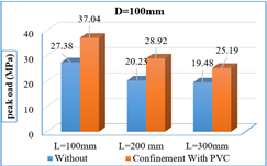
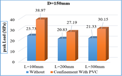
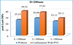
In general, confined concrete with a PVC tube significantly increases its Strength Enhancement Index (SEI) compared to an unconfined control sample (Eq. (1)). Specifically, the peak load capacity of samples in the group with a constant diameter of 100 mm (D1L1-2, D1L2-2, and D1L3-2) increased by 35.30%, 92.60%, and 89.60%, respectively, as shown in Figure 4(a). The lengths varied between 100 mm, 200 mm, and 300 mm, as shown in Figure 4(a). Similarly, in the group with a diameter of 150 mm (D2L1-2, D2L2-2, and D2L3-3), the increases were 18.40%, 30.50%, and 43.00%, respectively, as illustrated in Figure 4(b), when using the same lengths as the first group. The increases were 16.50%, 58.60%, and 38.10% for samples (D3L1-2, D3L2-2, and D3L3-3) with a diameter of 200 mm, as indicated in Figure 4(c), using the same lengths as the first group, compared with the unconfined samples, as shown in Table 7. Figure 5 shows the test of the specimens.
$SE{{I}_{PVC}}=\frac{{{f}_{CC,pvC}}-{{f}_{C}}}{fC}$ (1)
SEIPVC: Strength Enhancement Index
fc: The peak of unconfined concrete by PVC
fcc,pvc: The peak of confined concrete by PVC
(a)
(b)
(c)
Figure 4. The effect of polyvinyl chloride (PVC) confinement on the behavior of concrete: (a) diameter: 100 mm; (b) diameter: 150 mm; (c) diameter: 200 mm
Table 7. Examination results
|
Diameter (D) (mm) |
Length (L) (mm) |
Thickness (t)(mm) |
L/D |
ID Specimen |
Type of Confinement |
Max Load (MPa) |
SEI without PVC |
SEI with PVC |
|
100
|
100 |
|
|
D1L1-1 |
Without |
27.38 |
/ |
/ |
|
|
|
D1L1-2 |
Confinement With PVC |
37.04 |
35.3% |
/ |
||
|
2.5 |
1 |
D1L1-3 |
PVC + 1Layer CTRC |
40.44 |
47.7% |
9.2% |
||
|
|
|
D1L1-4 |
PVC + 2Layer CTRC |
50.18 |
83.3% |
35.5% |
||
|
|
|
D1L1-5 |
PVC + 3Layer CTRC |
52.5 |
91.75% |
41.74% |
||
|
200 |
|
|
D1L2-1 |
Without |
20.23 |
/ |
/ |
|
|
2.5 |
|
D1L2-2 |
Confinement With PVC |
28.92 |
42.96% |
/ |
||
|
|
2 |
D1L2-3 |
PVC + 1Layer CTRC |
35.91 |
77.51% |
24.2% |
||
|
|
|
D1L2-4 |
PVC + 2Layer CTRC |
40.31 |
99.26% |
39.4% |
||
|
|
|
D1L2-5 |
PVC + 3Layer CTRC |
42.16 |
108.40% |
45.8% |
||
|
300 |
|
|
D1L3-1 |
Without |
19.48 |
/ |
/ |
|
|
|
|
D1L3-2 |
confinement with PVC |
25.19 |
29% |
|
||
|
2.5 |
3 |
D1L3-3 |
PVC + 1Layer CTRC |
28.65 |
47% |
13.7% |
||
|
|
|
D1L3-4 |
PVC + 2Layer CTRC |
34.12 |
55% |
19.6% |
||
|
|
|
|
D1L3-5 |
PVC + 3Layer CTRC |
34.87 |
79% |
38.4% |
|
|
150 |
100 |
|
|
D2L1-1 |
Without |
23.73 |
/ |
/ |
|
|
|
D2L1-2 |
Confinement With PVC |
38.97 |
64.2% |
/ |
||
|
3 |
0.67 |
D2L1-3 |
PVC + 1Layer CTRC |
52.22 |
120.1% |
34.0% |
||
|
|
|
D2L1-4 |
PVC + 2Layer CTRC |
52.93 |
123.1% |
35.8% |
||
|
|
|
D2L1-5 |
PVC + 3Layer CTRC |
54.87 |
131.2% |
40.8% |
||
|
200 |
|
1.33 |
D2L2-1 |
Without |
20.83 |
/ |
/ |
|
|
|
D2L2-2 |
Confinement With PVC |
27.19 |
30.5% |
/ |
|||
|
3 |
D2L2-3 |
PVC + 1Layer CTRC |
31.54 |
51.4% |
16.0% |
|||
|
|
D2L2-4 |
PVC + 2Layer CTRC |
39.03 |
87.4% |
43.5% |
|||
|
|
D2L2-5 |
PVC + 3Layer CTRC |
42.94 |
106.1% |
57.9% |
|||
|
300 |
|
|
D2L3-1 |
Without |
21.33 |
/ |
/ |
|
|
3 |
2 |
D2L3-2 |
Confinement With PVC |
30.15 |
41% |
/ |
||
|
|
|
D2L3-3 |
PVC + 1Layer CTRC |
34.85 |
63% |
15.6% |
||
|
|
|
D2L3-4 |
PVC + 2Layer CTRC |
38.93 |
83% |
29.1% |
||
|
|
|
D2L3-5 |
PVC + 3Layer CTRC |
43.22 |
103% |
43.3% |
||
|
200 |
100 |
|
|
D3-L1-1 |
Without |
25.23 |
/ |
/ |
|
|
|
D3L1-2 |
Confinement With PVC |
39.52 |
56.6% |
/ |
||
|
|
0.5 |
D3L1-3 |
PVC + 1Layer CTRC |
47.17 |
87.0% |
19.4% |
||
|
4 |
|
D3L1-4 |
PVC + 2Layer CTRC |
52.92 |
109.8% |
33.9% |
||
|
|
|
D3L1-5 |
PVC + 3Layer CTRC |
54.74 |
117.0% |
38.5% |
||
|
200 |
|
|
D3L2-1 |
Without |
28.08 |
/ |
/ |
|
|
|
|
D3L2-2 |
Confinement With PVC |
37.61 |
%33.93 |
/ |
||
|
4 |
1 |
D3L2-3 |
PVC + 1Layer CTRC |
42.31 |
%50.68 |
12.50% |
||
|
|
|
D3L2-4 |
PVC + 2Layer CTRC |
46.67 |
%66.2 |
24.09% |
||
|
|
|
D3L2-5 |
PVC + 3Layer CTRC |
55.69 |
98.33% |
48.07% |
||
|
300 |
|
|
D3L3-1 |
Without |
23.11 |
/ |
/ |
|
|
|
|
D3L3-2 |
Confinement With PVC |
28.11 |
38.1% |
/ |
||
|
4 |
1.5 |
D3L3-3 |
PVC + 1Layer CTRC |
33.84 |
61.15% |
16.83% |
||
|
|
|
D3L3-4 |
PVC + 2Layer CTRC |
42.35 |
88.36% |
36.43% |
||
|
|
|
D3L3-5 |
PVC + 3Layer CTRC |
52.5 |
128.59% |
65.56% |
Note: Strength Enhancement Index (SEI), polyvinyl chloride (PVC), carbon textile-reinforced concrete (CTRC), length-to-diameter ratio (L/D).
Figure 5. Sample testing stages with and without polyvinyl chloride (PVC) confinement and carbon textile-reinforced concrete (CTRC) layers
3.2 Effect of carbon textile-reinforced concrete with polyvinyl chloride tube on the peak strength
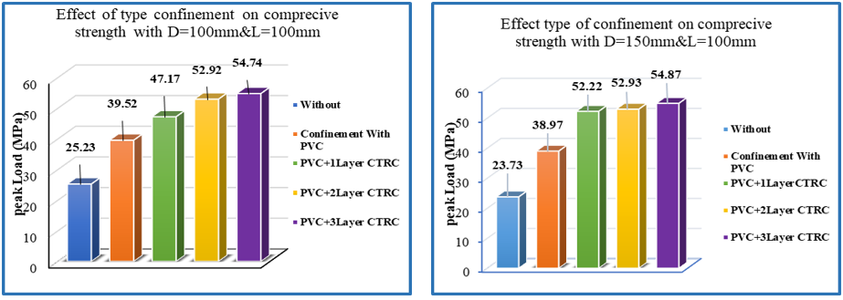
The technique of adding a CTRC mesh network is a method for strengthening concrete-filled tubes to enhance their durability and resistance to applied loads when added in one, two, or three layers. Strength enhancement index (SEI) for a diameter of 100 mm and a length of 100 mm (Eq. (2)), the load-bearing strength of the samples was 35.50% and 57.90% when using one, two, and three layers of CTRC mesh, respectively, compared to the reference sample confinement with PVC; when the length is 200 mm, the results are 10.00%, 34.00%, and 35.80% when using one, two, and three layers consecutively. At a length of 300 mm, the results for the samples with different layers—one, two, and three are 23.40%, 45.30%, and 55.50%, respectively. As indicated in Table 7 and Figure 6. Also, Figure 7 shows the test results of the specimens.
$S E I_{C T R C}=\frac{f_{C C, C T R C}-f_{c c, p v c}}{f_{c c, p v c}}$ (2)
where,
$S E I_{C T R C}$: Strength Enhancement Index
fcc,pvc: The peak of confined concrete by PVC
fCC,CTRC: The peak of confined concrete by PVC and strengthening by CTRC
The effect of using the first, second, and third layers of a CTRC on samples with a diameter of 150 mm and lengths of 100, 200, and 300 mm resulted in 33.90%, 35.90%, and 40.80% and 16.00%, 43.50%, and 57.90% and 24.20%, 39.40%, and 45.80%, respectively, as shown in Table 7 and Figure 7.
Figure 6. Effect of carbon textile-reinforced concrete (CTRC) with polyvinyl chloride (PVC) tube on the peak strength at D = 100 mm
Figure 7. Effect of carbon textile-reinforced concrete (CTRC) with polyvinyl chloride (PVC) tube on the peak strength at D = 150 mm
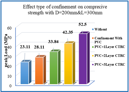
Figure 8. Effect of carbon textile-reinforced concrete (CTRC) with polyvinyl chloride (PVC) tube on the peak strength at D = 200 mm
Figure 9. Sample testing stages with and without polyvinyl chloride (PVC) Confinement and carbon textile-reinforced concrete (CTRC) layers
In the case of using the diameter (200 mm) with the CTRC and lengths (100 mm, 200 mm, and 300 mm), with one layer and two and three layers, the samples gave results of (19.40%, 33.90%, and 46.10%) and (18.80%, 12.50%, and 44.10%) and (16.83%, 36.43%, and 65.56%), respectively, as shown in Figure 8 and Table 7. Figure 9 shows the test stages of the specimens.
3.3 Effect of the length-to-diameter ratio on confinement and carbon textile-reinforced concrete layers
The peak load capacity of cylinders (without confinement) is inversely proportional to the L/D up to a ratio of less than 1, where it is observed that the larger the diameter, the lower the load-bearing capacity of the samples, since increasing this ratio reduces the confinement that occurs to the samples during testing between them and the machine, thus reducing their load-bearing capacity. In cases where the ratio of height to diameter is the same, the superiority tends towards the samples with the larger diameter, and this is entirely consistent with what the researchers Woldemariam et al. [36] and Ling and Chin [39] concluded. The optimal height-to-diameter ratio, which provides both strength and restriction, is 1. If this ratio is present and repeated, the larger diameter will be the stronger limiter. Similarly, a thicker tube will have a higher load-bearing capacity than its counterparts, as detailed in Figure 10 and Table 7.

Figure 10. Results of the sample without and with polyvinyl chloride (PVC) confinement and with carbon textile-reinforced concrete (CTRC) layers
3.4 Stress-strain relation
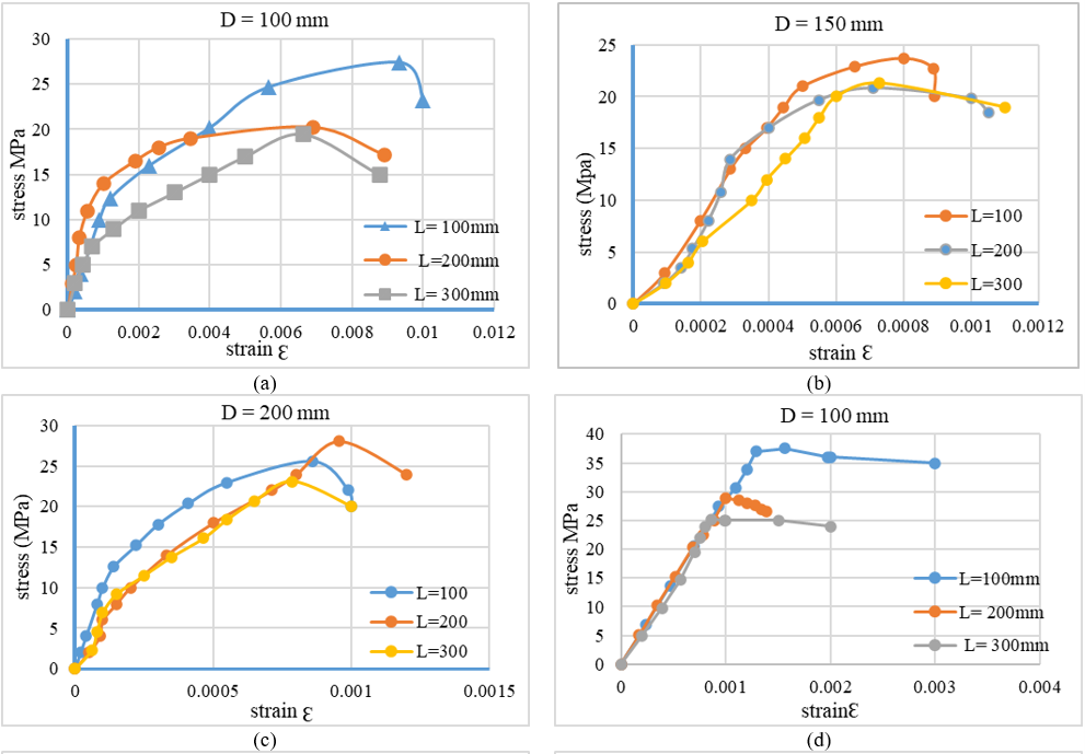
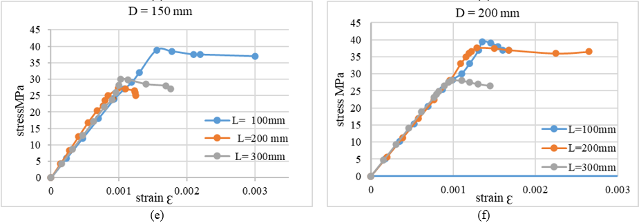
To determine the behavior and failure patterns of confined and unconfined concrete, a strain strip was installed on unrestrained concrete and on a PVC tube for confined concrete to determine the stress-strain behavior. The stress-strain behavior shown in Figure 11(a), (b), and (c) indicates that all unconfined concrete specimens exhibit nearly linear behavior during the elastic phase before brittle failure. The presence of the PVC tube led to a transformation in the concrete's behavior from brittle to almost ductile, as illustrated in Figure 11(d), (e), and (f). Initially, the constrained concrete exhibited linear behavior, but after the plasticization stage, the line continued straight due to the tube bearing the lateral pressure of the concrete before specimen failure. However, this failure stage was not abrupt. Furthermore, the constraining of the concrete increased its strain by 38%, 45%, and 30% for diameters of 100 mm and lengths of 100 mm, 200 mm, and 300 mm, respectively. Similarly, the strain of the constrained concrete with a diameter of 150 mm increased by 94%, 39%, and 37% for lengths of 100 mm, 200 mm, and 300 mm, respectively. Likewise, the constrained concrete with a diameter of 200 mm achieved increases of 57%, 34%, and 24% for lengths of 100 mm, 200 mm, and 300 mm, respectively.
Figure 11. Stress-strain curves for (a) unconfined cote D100, (b) unconfined concrete D150, (c) unconfined concrete D200, (d) confined concrete D100, (e) confined concrete D150 and (f) confined concrete D200ncre
The following are the most significant conclusions achieved in this study:
1. The peak load capacity of concrete specimens is inversely proportional to the L/D ratio, resulting in a decrease in heaviness and a greater impact from lateral loads or lateral stresses generated by axial pressure on unconstrained cylinders. The same applies to constrained specimens; this effect occurs until the ratio reaches one.
2. When the L/D ratio is the same in the samples, the controlling factor in this case is the tube thickness and the tube diameter, as the ratio increases with an increase in either of these.
3. PVC strengthening has a significant role in providing confinement for the concrete inside, preventing its premature collapse or buckling of the specimens, as it enhances and increases the ductility of the concrete and provides confinement from a third side, in addition to confining the machine from above and below the concrete, thus improving the load-bearing capacity of all the confinement specimens.
4. When strengthening the concrete with a PVC tube using CTRC, this process provides additional confinement to the existing confinement using PVC, thus giving additional strengthening to its resistance to lateral loads generated as a result of vertical loads from the top and bottom of the cylindrical specimens.
5. Lateral expansion resistance of specimens increases with increasing confinement, and confinement increases with increasing number of CTRC layers, and this is particularly noticeable if there is more than one layer of CTRC. It promotes making the concrete a single, confined mass from all stresses in all directions, which makes the failure of the concrete due to the materials or reaching its maximum strength.
6. When a concrete core is subjected to an axial load, it expands laterally due to Poisson's ratio, resulting in uniaxial stresses. PVC transforms the stress from uniaxial to triaxial, significantly increasing strength. Adding CTRC layers also increases the lateral stiffness of the concrete core, ensuring uniform stress distribution by providing high tensile strength that restricts PVC's transverse expansion and prevents premature PVC failure under transverse stresses. This improves stress transfer efficiency across the surface and enhances energy absorption.
7. Finally, confining the concrete and strengthening this confinement with layers of CTRC improves the strength and ductility of the specimens, thereby strengthening their weak point in resisting lateral stresses. Therefore, it is recommended to conduct a feasibility study of these strengthening techniques on reinforced concrete column samples with a length-to-diameter ratio greater than 3 and 4 to determine the extent of improvement.
The authors would like to acknowledge the University of Diyala for providing the opportunity to conduct all research work in the structural lab of the Engineering Department in the College of Engineering. Gratitude is extended to the staff of the lab for collaborating and assisting.
AI usage disclosure: AI-assisted tools were used solely for language editing and manuscript organization. No AI tools were used to generate scientific content, data, or interpretations. The authors take full responsibility for the accuracy, integrity, and originality of the work.
|
D |
diameter |
|
L/D |
length-to-diameter ratio |
|
OPC |
ordinary Portland cement |
|
PVC |
polyvinyl chloride |
|
RC |
reinforced concrete |
|
SEI |
strength enhancement index |
|
t |
thickness |
|
CTRC |
carbon textile-reinforced concrete |
|
uPVC |
unplasticized polyvinyl chloride |
|
w/c |
water-to-cement ratio |
|
ECC |
engineered cementitious composite |
|
GFRC |
glass-fiber-reinforced concrete |
|
FRP |
fiber-reinforced polymer |
|
CFRP |
carbon fiber-reinforced polymer |
[1] Eilbeigi, S., Tavakkolizadeh, M., Masoodi, A.R. (2023). Nonlinear regression prediction of mechanical properties for SMA-confined concrete cylindrical specimens. Buildings, 13(1): 112. https://doi.org/10.3390/buildings13010112
[2] Xu, Y., Tang, H., Chen, J., Jia, Y., Liu, R. (2021). Numerical analysis of CFRP-confined concrete-filled stainless steel tubular stub columns under axial compression. Journal of Building Engineering, 37: 102130. https://doi.org/10.1016/j.jobe.2020.102130
[3] Li, W., Han, L.H., Zhao, X.L. (2015). Behavior of CFDST stub columns under preload, sustained load and chloride corrosion. Journal of Constructional Steel Research, 107: 12-23. https://doi.org/10.1016/j.jcsr.2014.07.021
[4] Fakharifar, M., Chen, G. (2016). Compressive behavior of FRP-confined concrete-filled PVC tubular columns. Composite Structures, 141: 91-109. https://doi.org/10.1016/j.compstruct.2016.01.004
[5] Berg, A.C., Bank, L.C., Oliva, M.G., Russell, J.S. (2006). Construction and cost analysis of an FRP reinforced concrete bridge deck. Construction and Building Materials, 20(8): 515-526. https://doi.org/10.1016/j.conbuildmat.2005.02.007
[6] Ozbakkaloglu, T., Xie, T. (2016). Geopolymer concrete-filled FRP tubes: Behavior of circular and square columns under axial compression. Composites Part B: Engineering, 96: 215-230. https://doi.org/10.1016/j.compositesb.2016.04.013
[7] Wang, J.Y., Yang, Q.B. (2012). Investigation on compressive behaviors of thermoplastic pipe confined concrete. Construction and Building Materials, 35: 578-585. https://doi.org/10.1016/j.conbuildmat.2012.04.017
[8] Li, Y.L., Zhao, X.L., Singh Raman, R.K. (2018). Mechanical properties of seawater and sea sand concrete-filled FRP tubes in artificial seawater. Construction and Building Materials, 191: 977-993. https://doi.org/10.1016/j.conbuildmat.2018.10.059
[9] Jiang, T., Wang, X.M., Chen, G.M., Zhang, J.J., Zhang, W.P. (2019). Behavior of recycled brick block concrete-filled FRP tubes under axial compression. Engineering Structures, 198: 109498. https://doi.org/10.1016/j.engstruct.2019.109498
[10] Wu, P., Liu, J., Yu, F., Fang, Y., Zhu, D. (2021). Testing and numerical modeling of PVC-CFRP confined concrete column-reinforced concrete beam joint under axial load. Iranian Journal of Science and Technology - Transactions of Civil Engineering, 45(2): 639-651. https://doi.org/10.1007/s40996-020-00412-x
[11] Yu, F., Bu, S., Li, D., Feng, C., Fang, Y. (2021). Experimental investigation and theoretical study on bearing capacity of strong PVC-FRP confined concrete column-weak joint strengthened with core steel tube under axial loading. Construction and Building Materials, 271: 121880. https://doi.org/10.1016/j.conbuildmat.2020.121880
[12] Shang, L., Isleem, H.F., Alsaadawi, M.M. (2025). Deep learning-based modelling of polyvinyl chloride tube-confined concrete columns under different load eccentricities. Engineering Applications of Artificial Intelligence, 145: 110217. https://doi.org/10.1016/j.engappai.2025.110217
[13] Shen, J., Liang, J., Lin, X., Lin, H., Yu, J., Yang, Z. (2020). Recent progress in polymer-based building materials. International Journal of Polymer Science, 2020: 8838160. https://doi.org/10.1155/2020/8838160
[14] Hassan, A.A. (2018). The potential application of bio-polymeric materials in building: A framework of multi-performance criteria matrix for selecting optimal materials by the AHP and TOPSIS methods. In Proceedings of the Building Enclosure Science and Technology (BEST5) Conference, Philadelphia, PA, USA.
[15] European Commission. (2012). Horizon 2020-EU Bioeconomy Research and Innovation. European Commission, Brussels, Belgium.
[16] Correia, D.A. (2015). Polymers in building and construction. In Materials for Construction and Civil Engineering, Springer, Cham, Switzerland, pp. 447-499. https://link.springer.com/chapter/10.1007/978-3-319-08236-3_10.
[17] Oprişan, G., Ţăranu, N., Munteanu, V., Enţuc, I. (2010). Application of modern polymeric composite materials in industrial construction. Bulletin of the Polytechnic Institute of Iași, 56: 121-130.
[18] Nurkulov, F., Ziyamukhamedova, U., Rakhmatov, E., Nafasov, J. (2021). Slowing down the corrosion of metal structures using polymeric materials. E3S Web of Conferences, 264: 02055. https://doi.org/10.1051/e3sconf/202126402055
[19] Yang, T.C., Wu, J.H., Noguchi, T., Isshiki, M. (2014). Methodology of accelerated weathering test through physicochemical analysis for polymeric materials in building construction. Materials Research Innovations, 18(sup3): S3-91-95. https://doi.org/10.1179/1432891714Z.000000000587
[20] Wang, F., Lu, X., He, C. (2011). Some recent developments of polyhedral oligomeric silsesquioxane (POSS)-based polymeric materials. Journal of Materials Chemistry, 21(9): 2775-2782. https://doi.org/10.1039/C0JM02785E
[21] Mosallam, A.S., Bayraktar, A., Elmikawi, M., Pul, S., Adanur, S. (2014). Polymer composites in construction: An overview. SOJ Materials Science & Engineering, 2: 1-25. https://doi.org/10.15226/sojmse.2014.00107
[22] Motavalli, M., Czaderski, C., Schumacher, A., Gsell, D. (2010). Fibre reinforced polymer composite materials for building and construction. In Textiles, Polymers and Composites for Buildings, Woodhead Publishing, pp. 69-128. https://doi.org/10.1533/9780845699994.1.69
[23] Yu, C., Crump, D. (1998). A review of the emission of VOCs from polymeric materials used in buildings. Building and Environment, 33(6): 357-374. https://doi.org/10.1016/S0360-1323(97)00055-3
[24] Giannopoulou, I., Dimas, D., Maragkos, I., Panias, D. (2009). Utilization of metallurgical solid by-products for the development of inorganic polymeric construction materials. Global NEST Journal, 11(2): 127-136. https://doi.org/10.30955/gnj.000589
[25] Sakkas, K., Nomikos, P., Sofianos, A., Panias, D. (2014). Utilisation of FeNi-slag for the production of inorganic polymeric materials for construction or for passive fire protection. Waste and Biomass Valorization, 5(3): 403-410. https://doi.org/10.1007/s12649-013-9278-z
[26] Saeedifar, M., Najafabadi, A.M., Zarouchas, D., Toudeshky, H.H., Jalalvand, M. (2018). Clustering of interlaminar and intralaminar damages in laminated composites under indentation loading using acoustic emission. Composites Part B: Engineering, 144: 206-219. https://doi.org/10.1016/j.compositesb.2018.02.028
[27] He, L., Zhao, Y., Lin, S. (2018). Experimental study on axially compressed circular CFST columns with improved confinement effect. Journal of Constructional Steel Research, 140: 74-81. https://doi.org/10.1016/j.jcsr.2017.10.025
[28] Zhao, X.L., Han, L.H. (2006). Double skin composite construction. Progress in Structural Engineering and Materials, 8(3): 93-102. https://doi.org/10.1002/pse.216
[29] Guo, Y.C., Huang, P.Y., Yang, Y., Li, L.J. (2009). Experimental studies on axially loaded concrete columns confined by different materials. Key Engineering Materials, 400: 513-518. https://doi.org/10.4028/www.scientific.net/KEM.400-402.513
[30] Han, L.H., Li, W., Bjorhovde, R. (2014). Developments and advanced applications of concrete-filled steel tubular (CFST) structures: Members. Journal of Constructional Steel Research, 100: 211-228. https://doi.org/10.1016/j.jcsr.2014.04.016
[31] Wang, X., Fan, F., Lai, J. (2022). Strength behavior of circular concrete-filled steel tube stub columns under axial compression: A review. Construction and Building Materials, 322: 126144. https://doi.org/10.1016/j.conbuildmat.2021.126144
[32] Ling, J.H., Omoregie, A.I. (2025). A bibliometric overview of current states and research trends in concrete-filled tube columns. Journal of Civil Engineering, 40(2): 191-205. https://doi.org/10.12962/j20861206.v40i2.22784
[33] Abdulla, N.A. (2017). Concrete filled PVC tube: A review. Construction and Building Materials, 156: 321-329. https://doi.org/10.1016/j.conbuildmat.2017.08.156
[34] Oyawa, W.O., Gathimba, N.K., Mang’uriu, G.N. (2016). Structural response of composite concrete filled plastic tubes in compression. Steel and Composite Structures, 21(3): 589-604. https://doi.org/10.12989/scs.2016.21.3.589
[35] Askari, S.M., Khaloo, A., Borhani, M.H., Masoule, M.S. (2020). Performance of polypropylene fiber reinforced concrete-filled UPVC tube columns under axial compression. Construction and Building Materials, 231: 117049. https://doi.org/10.1016/j.conbuildmat.2019.117049
[36] Woldemariam, A.M., Oyawa, W.O., Nyomboi, T. (2019). Structural performance of uPVC confined concrete equivalent cylinders under axial compression loads. Buildings, 9(4): 82. https://doi.org/10.3390/buildings9040082
[37] Hammadi, A.A., Khaleel, F., Afan, H.A., Khan, M.M.H., Sulaibi, A.A.H. (2022). Study of behaviour of short concrete columns confined with PVC tube under uniaxial load. Applied Sciences, 12(22): 11427. https://doi.org/10.3390/app122211427
[38] Chen, X., Li, R., Xiong, Z., Liu, Y., Zhuge, Y. (2025). Experimental study on axial behavior of pre-damaged concrete columns confined with carbon textile-reinforced ECC. Construction and Building Materials, 458: 139582. https://doi.org/10.1016/j.conbuildmat.2024.139582
[39] Ling, J.H., Chin, W.Q. (2026). Experimental study on concrete-filled PVC tubes using E-glass fibre reinforced concrete. Journal of Civil Engineering, 41(1): 20-31. https://doi.org/10.12962/j25799029.v41i1.9495
[40] Central Organization for Standardization and Quality Control (COSQC). (1984). Portland cement. Iraqi Standard Specification No. 5/1984. Baghdad, Iraq.
[41] Central Organization for Standardization and Quality Control (COSQC). (1984). Aggregates from natural sources for concrete and building construction. Iraqi Standard Specification No. 45/1984. Baghdad, Iraq.