Omar A. Mohammed* | Anas A. Balood | Ahmed N. Rashid | Nooraldeen Saleh Khidhir
© 2026 The authors. This article is published by IIETA and is licensed under the CC BY 4.0 license (http://creativecommons.org/licenses/by/4.0/).
OPEN ACCESS
This study numerically investigates the free vibration characteristics of simply supported, hybrid (Kevlar/E-glass epoxy) laminated composite beams. A comprehensive finite element model was developed in ANSYS using a 2 mm mesh size to evaluate the coupled effects of Kevlar hybridization and full-width delamination. The investigated variables include the number of Kevlar layers (0 to 10), Kevlar layer positions, delamination length ratios (a/L = 0 to 0.9), and delamination depth positions (t/h = 1/5 to 5/5). Quantitative results, evaluated against an intact, pure E-glass baseline (30.115 Hz), demonstrate that replacing the two outermost glass layers with Kevlar increases the first natural frequency by approximately 30%, achieving a maximum stiffness enhancement of 78% for the all-Kevlar configuration. Conversely, the presence of a near-surface delamination (t/h = 1/5) at a length ratio of a/L = 0.9 severely degrades the structural integrity, causing a dramatic frequency drop of up to 80% relative to the baseline. These findings provide crucial design guidelines for optimizing the dynamic performance and structural health monitoring of hybrid composite components.
vibrations, hybrid fiber, finite element method, ANSYS, delamination
Composite materials [1, 2] and composite beams [3-5] have been recently studied by many researchers. It is well known that one of the main properties that composite materials propose is their high strength-to-weight ratio. This feature, in particular, makes them appropriate in load-bearing component applications such as aeronautical industries, naval and aerospace. Some properties like wear resistance, corrosion, strength, specific weight, toughness and thermal stresses can be improved by placing the fibers in the correct directions and constructing a specific composite material. However, some degradation phenomena should be considered properly in regard to laminated composite design. In composites, there are many types of fibers that can be utilized to reinforce composites. Among those types, the most desirable ones are those that have characteristics such as low density, high strength and high stiffness. Based on that, glass fibers are commonly applied in relatively moderate-performance composites due to their low cost and high tensile strength. To meet greater performance requirements, various materials have been combined for thousands of years. The combination of different materials has been employed for thousands of years. Laminated composite plates, in particular, consist of several bonded layers, each typically orthotropic with varying fiber orientations [6]. Kevlar is essentially an aromatic organic molecule consisting of carbon, hydrogen, oxygen, and nitrogen. The low density, high tensile strength, and low price of Kevlar fibers make them advantageous. Kevlar exhibits great stiffness and strength, lightweight characteristics, vibration damping capacity, low density and resistance to wear, fatigue, and stress ruptures. However, its main drawbacks are low compressive strength and poor machinability. The use of Kevlar fibers is possible only when it is compounded with carbon or glass fibers, where bending and numerical compression are mostly present, for structural parts like a shell [7].
Several damages, such as crack [8-10] and delamination [11-14], can affect the behaviour of composite structures and there are two main reasons may lead to delamination: fabrication process mistakes, i.e., air leakage between layers and/ or incomplete wetting, the other cause can be related to a specific service factors like foreign objects which can be activated at low velocity. It is well known that degradation in stiffness and overall laminates’ strength is caused by delamination damage; moreover, how that is related to vibration features was already studied by many researchers. The delamination length plays an important role in determining the delaminated beam, which shows different vibration modes and frequencies [15].
The most important and relevant works on the vibration are summarised as follows: Norman and Mahmud [16] examined the influence of several boundary conditions, lamination schemes, as well as fiber compositions on hybrid composite laminated plates’ natural frequencies. Employing the Finite Element Analysis (FEA) and ANSYS software, a model of a hybrid composite laminate, i.e., Kevlar/glass, at free vibration was developed to carry out a parametric study of different compositions of Kevlar and glass fibers, various lamination schemes and many boundary conditions like Clamp-Clamp-Clamp-Clamp (CCCC), Free-Free-Free-Free (FFFF), and Clamp-Free-Free-Free (CFFF). Similarly, FEM was utilized in characterizing the natural frequencies of hybrid laminated composite plates and determining the plates’ deformation behavior through their mode shapes. In terms of its cross-ply laminates, it is found that increasing the Kevlar composition led to higher plate natural frequencies. Also, it is determined that while CFFF produced the lowest natural frequency of 37.248 Hz, the CCCC formed the maximum natural frequency of 859.49 Hz [16].
Another important work on vibration has been carried out by Erkliğ et al. [17], who studied the consequence of cutouts under the clamped-free boundary condition with respect to the hybridization of woven laminated hybrid composite beams in terms of their natural frequency values. To produce hybrid composites, Kevlar and S-glass fibers with epoxy and woven were utilized. For [(0/90)3]s stacking sequence hybrid composite beams, their natural frequencies were experimentally evaluated. On the other hand, numerical analyses were performed to investigate the impact of each angle of fiber orientation, as well as the sizes, placements, and ratios of the cuts that are round and rectangular, on natural frequency. With a slight difference between the numerical and experimental results, the authors concluded that the natural frequency is strongly affected by the fiber type employed in the layers, the beam’s cutout position and size values.
Similarly, Ma et al. [18] examined, using ABAQUS software, the free vibration analysis of Kevlar/glass/epoxy resin hybrid composite laminates at various fiber hybridization. Using the 3D shell element and quasi-isotropic laminated composite, various models were evaluated in terms of mode shape and natural frequency. Furthermore, ANSYS software was also employed to increase the accuracy of the numerical results when the latter were compared with those from ABAQUS software. The results showed that element size, i.e., mesh accuracy, has a significant influence on the obtained results. On the other hand, the satisfactory agreement between numerical results obtained from ANSYS software and the experimental ones can enhance the free vibration analysis of composite laminates.
Using an experimental approach, Prashanth and Basava [19] conducted an important study to investigate the vibration of natural hybrid vehicles in an experimental manner. What is interesting is that the modern approach uses artificial neural networks to predict the mechanical properties and failure of materials and structures.
There are several other studies and tests carried out. Nayak [20] carried out numerical models and practical testing to determine the free vibrations of composite plates made of woven fiberglass and epoxy laminate. Also, Norman et al. [21] investigated the free vibration characteristics of carbon/epoxy laminated composite beams using ANSYS finite element simulations. The study analyzes the effects of varying the aspect ratio (length to thickness, ranging from 25 to 150), three fiber lamination schemes (unidirectional, cross-ply, and angle-ply), and five different boundary conditions on the beams' natural frequencies. The results demonstrate that increasing the beam's aspect ratio consistently decreases its natural frequencies across all mode shapes. Specifically, the unidirectional ply and the hanger-hanger boundary condition produced the highest natural frequencies, whereas the angle-ply and the clamped-free boundary condition resulted in the lowest, providing crucial insights into the dynamic stability of these structures [21]. ANSYS software and an analytical technique were utilized to examine the free vibrations of the laminated composite beam caused by the effect of lamination schemes [22].
On the other hand, the most important and relevant works on delamination are summarised as follows:
Çallioğlu and Atlihan [23] examined, numerically and analytically, using the Timoshenko beam theory, the effects of orientation angle as well as the delamination length on the symmetric composite beams’ natural frequency. Using a contact element with FEA in ANSYS software, a 2D model of the delaminated beams was carried out. With an almost negligible difference between the numerical and analytical results, it was concluded that the change of orientation angle has a substantial impact on the natural frequencies. Moreover, the beam delamination length decreases at higher natural frequency values.
Using ABAQUS software, both the natural frequencies and mode shapes of the transverse vibration of the delaminated cross-ply composite beam were experimentally and theoretically studied by Torabi et al. [24]. The achieved results were obtained under both the clamped-clamped and clamped-free circumstances. The authors referred to delamination detection that can be achieved as a result of the presented interesting relationships between the frequency lowering and their associated mode forms. Della and Shu [25] found analytical solutions using the Euler-Bernoulli beam theory for the free vibrations of multiple delaminated beams under axial compressive loads. The result showed decreased natural frequency with an increase in the length of delamination.
A study by Imran et al. [26] talked about the delamination that started and led to the significant failure of laminated composite structures, which was influenced by the vibration qualities and dynamic characteristics.
To clearly highlight the scientific novelty of this work, it is completely focused on the free vibration behavior of symmetric laminated composite beams with simply supported conditions. The influence of the Kevlar layer and its region for the hybrid laminate (Kevlar/glass) fiber with an epoxy composite beam, and then the effect of delamination length and position, are investigated numerically using the FEA package (ANSYS). First, an optimal hybridization strategy is established, demonstrating that placing Kevlar as the outermost layer maximizes dynamic stiffness with a 30% natural frequency boost, whereas mid-plane placement yields negligible effects. Second, universal safe structural thresholds are identified, establishing a safe delamination limit (a/L ≤ 0.3) where the beam's natural frequency remains uncompromised across all defect depths. Finally, a critical damage mapping is provided, quantifying the risk zones to show that near-surface delamination (t/h = 0.1) is highly critical, causing a sharp 80% frequency drop compared to only a 14% reduction for mid-plane defects.
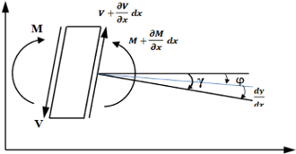
Figure 1 illustrates the beam element’s geometry and free-body diagram according to the Timoshenko beam theory. This accounts for the beam’s shear deformation and rotary inertia. When the symmetric beam vibrates transversely, the condition of dynamic equilibrium for y-direction shearing forces reveals the relationship between the beam element’s inertial moment and the moment equilibrium condition [27].
Figure 1. Geometry for a beam element
The differential equation for the beam’s transverse vibration has the following form:
$\frac{E_{e f} I_{y y}}{\rho_m} \frac{\partial^4 y(x, t)}{\partial x^4}=I_{y y} \frac{\partial^4 y}{\partial x^2 \partial t^2}-\frac{A \partial^2 y(x, t)}{\partial t^2}$ (1)
where, Eef is effective modulus of elasticity, Iyy is the moment of inertia, ρm is density and A is the cross-sectional area. The effective elastic modulus can be obtained as follows:
$E_{e f}=\frac{m}{h^3} \sum_{j=1}^{\frac{m}{2}}\left(E_x\right)_j\left(z_j^3-z_{j-1}^3\right)$ (2)
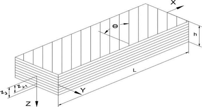
where, Ex is modulus of elasticity of the jth layer, m is beam layer number and h is beam height, as shown in Figure 2.
Figure 2. Geometry and coordinate system of laminated composite beam
The rotation of the beam's cross-section and the shearing deformations both influence the deflection curve's slope. By neglecting the shearing force, the total slope can be written as:
$\frac{d y}{d x}=\gamma+\varphi$ (3)
where, $\gamma$ is the deflection curve's slope and $\varphi$ is the angle of shearing force at the neutral axis. The shearing force $V$ and bending moment $M$ can be obtained as follows:
$V=-k \varphi A G=-k\left(\frac{d y}{d x}-\gamma\right)$ (4)
$M=E_{e f} I_{y y} \frac{d \gamma}{d x}$ (5)
where, $k$ is the cross-section form factor and $G$ is modulus of rigidity. The value of form factor for a rectangular cross-sectional beam is 6/5. By eliminating $\gamma$, the differential equation can be written as:
$\frac{E_{e f} I_{y y}}{\rho_m} \frac{\partial^4 y}{\partial x^4}+A \frac{\partial^2 y}{\partial t^2}-I_{y y}\left(1+\frac{E_{e f}}{K G}\right) \frac{\partial^4 y}{\partial x^2 \partial t^2}+\frac{\rho_m I_{y y}}{k G} \frac{\partial^4 y}{\partial x^4}=0$ (6)
In the case of a simply supported beam, this equation, as well as the boundary condition, is satisfied by considering:
$w_n=\left(\sin \frac{n \pi x}{L}\right)\left(A_n \cos p_n t+B_n \sin p_n t\right)$ (7)
where, $n$ is number of modes, while $A_n$ and $B_n$ are constants.
$A_n=\frac{2}{l} \int_0^1 f_1(x) \sin \frac{n \pi x}{l} d x$ (8)
$B_n=\frac{2}{l p_n} \int_0^1 f_2(x) \sin \frac{n \pi x}{l} d x$ (9)
where, $y_0=f_1(x)$ is initial transverse displacement and $\dot{y}_0=f_2(x)$ is initial velocity of any point on the beam. The frequencies can be evaluated by substituting Eq. (7) into Eq. (6):
$\frac{E_{e f} I_{y y}}{\rho_m A} \frac{n^4 \pi^4}{L^4}-p_n{ }^2-p_n{ }^2 \frac{n^2 \pi^2 I_{y y}}{L^2 A}-p_n{ }^2 \frac{n^2 \pi^2 I_{y y}}{L^2 A} \frac{E_{e f}}{k G}+\frac{I_{y y} \rho_m}{A k G} p_n{ }^4=0$ (10)
When neglecting the last term (fourth order) to simplify the solution, the angular frequencies can be expressed as:
$p_n=\frac{\pi^2}{\lambda_n^2} \sqrt{\frac{E_{e f} I_{y y}}{\rho_m A}}\left[1-\frac{\pi^2 I_{y y}}{2 \lambda_n^2 A}\left(1+\frac{E_{e f}}{k G}\right)\right]$ (11)
where, $\lambda_n=\frac{L}{n}$ and $L$ is beam length. The natural frequencies of free vibration are:
$\omega_n=\frac{p_n}{2 \pi}$ (12)
If the laminated beam contains delamination, whether it is partial or totally delaminated, the following equations are used to evaluate longitudinal Young’s modulus [28].
$E_{z d}=\frac{\sum_{j=1}^s E_{e f} Z_j}{z}$ (13)
$E_d=\left(E_{z d}-E_{e f}\right) \frac{A_d}{A_t}+E_{e f}$ (14)
where, $E_{z d}$ and $E_d$ are the longitudinal modulus of elasticity of the laminated composite beam, totally and partially delaminated, respectively. Similarly, $A_d$ and $A_t$ delaminated area and total interfacial region, respectively.
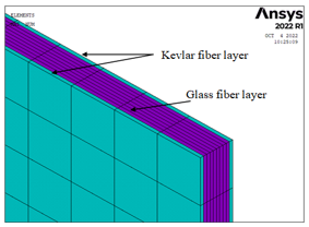
In many engineering problems, the finite element method (FEM) is considered a powerful tool to be employed in laminated composite beam applications like thermal stress, elastic–plastic, vibration and buckling analysis. The vibration behaviour of laminate composite beams is investigated numerically using ANSYS software. Composite laminated beams were modeled using multi-layer shell elements (shell 281), the element having 8-node, which has six degrees of freedom at each node, including translations in the (x, y, and z) directions and rotations about the nodal axes (x, y and z). Asymmetric laminates with 0° fiber orientation (unidirectional laminates) were nominated in this study. The constructed finite element (FE) model contains ten layers, each of which has independent material properties and fiber orientation. To model the hybrid fiber composite laminate, two types of materials were employed. Figure 3 shows a hybrid laminate containing two plies of Kevlar and eight plies of glass fiber.
Figure 3. Fiber types of hybrid laminate
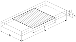
A specimen with delamination is shown in Figure 4. In this figure, a is delamination length, and t delamination depth. In contrast, the constant variables are: span (L = 440 mm), thickness (h = 3 mm) and width (b = 20 mm).
Figure 4. Specimen with delamination
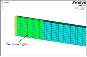
Two sub-laminates were modeled to illustrate delamination; the nodes were linked at the interface, with the exception of the delamination zone, where contact pairs were applied to prevent sub-laminates from overlapping. Specimens were chosen with nine different lengths of delamination (a/L= 0.1, 0.2, 0.3, 0.4, 0.5, 0.6, 0.7, 0.8 and 0.9) generated at five different positions (t/h = 0.1, 0.2, 0.3, 0.4 and 0.5). An FE model with a delamination length (a/L) equal to 0.8 is shown in Figure 5, where two sub-laminates are constrained in the region that is not delaminated.
In the modal analysis, the contact behavior at the delamination interface was inherently linearized by the eigenvalue extraction solver based on the initial contact status. To accurately simulate the interaction between the upper and lower sub-laminates at the delaminated region, specific contact parameters were defined. The intact regions were perfectly bonded, while the delaminated region was assigned a frictionless contact to prevent penetration without adding artificial shear stiffness. The detailed contact settings used in the FE model are summarised in Table 1. To simulate a simply supported laminated composite beam at both ends, all nodes at both ends were set to their displacement (x, y, z) and rotation (θx, θz) to zero, except for the rotation about the y-axis.
Figure 5. Model with delamination length (a/L) equals 0.8
Table 1. Contact settings and parameters used in the finite element (FE) model
|
Parameter |
Setting / Value |
|
Contact behavior (Intact region) |
Bonded |
|
Contact behavior (Delaminated region) |
Frictionless |
|
Contact formulation algorithm |
Augmented lagrange |
|
Normal stiffness factor (FKN) |
1.0 |
|
Friction coefficient |
0.0 (Ignored in linear modal analysis) |
|
Eigenvalue contact treatment |
Linearized (Based on initial status) |
To ensure the numerical stability of the finite element model, a sensitivity analysis was conducted on a selected representative case. A rigorous mesh convergence study was performed by systematically reducing the element size from 10 mm down to 1 mm (specifically: 10, 5, 4, 2, 1mm). The results demonstrated exceptional stability, as the first three natural frequencies exhibited no significant variation (0% change), confirming complete mesh independence.
The properties of Kevlar fiber/Epoxy laminate [29] and E-glass/epoxy laminate [30], which were selected during the FE analysis settings, are illustrated in Table 2.
Table 2. Properties of Kevlar/epoxy and E-glass/epoxy [29, 30]
|
Composite Laminate |
Kevlar/Epoxy |
E-Glass/ Epoxy |
|
Longitudinal modulus (E11), GN/m² |
80 |
36.5 |
|
Transverse modulus (E22), GN/m² |
5.5 |
15 |
|
Major Poisson’s ratio (υ12) |
0.34 |
0.24 |
|
Out of plane Poisson’s ratio (υ21) |
0.4 |
0.22 |
|
In plane shear modulus (G12), GN/m² |
2.2 |
6.35 |
|
Out of plane shear modulus (G21), GN/m² |
1.8 |
1.6 |
|
Density (ρ), kg/m3 |
1380 |
1985 |
To further validate the developed finite element model, a comparison was performed for the intact pure E-glass beam ([(G0)5]s) against the analytical solution derived from the Timoshenko beam theory (Eq. (12)). The analytical calculation yielded a first natural frequency of 30.13 Hz, while the ANSYS FE model predicted a frequency of 30.115 Hz. The relative error between the analytical and numerical approaches is exceptionally low (0.05%), conclusively validating the accuracy and reliability of the FE model before proceeding to the hybridization and delamination studies.
To eliminate any ambiguity in the laminate definition, Table 3 explicitly details the layer-by-layer stacking sequence from top to bottom for the representative hybrid configuration [K0/(G0)4]s. The table also specifies the exact interfaces where the delamination (t/h) was introduced.
Table 3. Detailed stacking sequence (top to bottom) for the hybrid [K0/(G0)4]s beam and delamination locations
|
Layer No. |
Material |
Thickness (mm) |
Fiber Angle |
Delamination Interface Depth (t/h) |
|
1 (Top) |
Kevlar/ Epoxy |
0.3 |
0° |
← Delamination at t/h = 0.1 (Interface 1/2) |
|
2 |
E-glass/ Epoxy |
0.3 |
0° |
← Delamination at t/h = 0.2 (Interface 2/3) |
|
3 |
E-glass/ Epoxy |
0.3 |
0° |
← Delamination at t/h = 0.3 (Interface 3/4) |
|
4 |
E-glass/ Epoxy |
0.3 |
0° |
← Delamination at t/h = 0.4 (Interface 4/5) |
|
5 |
E-glass/ Epoxy |
0.3 |
0° |
← Delamination at t/h = 0.5 (Midplane, Interface 5/6) |
|
6 |
E-glass/ Epoxy |
0.3 |
0° |
|
|
7 |
E-glass/ Epoxy |
0.3 |
0° |
|
|
8 |
E-glass/ Epoxy |
0.3 |
0° |
|
|
9 |
E-glass/ Epoxy |
0.3 |
0° |
|
|
10 (Bottom) |
Kevlar/ Epoxy |
0.3 |
0° |
|
4.1 Kevlar fiber effect
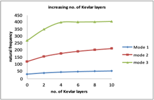
Natural frequency values of the hybrid laminated composite beam were obtained numerically using FEA by increasing the number of Kevlar fiber layers first and then by changing the position of the Kevlar layer as listed in Table 4. The natural frequency values of 10 layers unidirectional laminate with a 0° orientation angle are determined. Figure 6 illustrates how increasing Kevlar fiber layers affects the natural frequency of a composite laminated beam. It was noted that as the number of Kevlar fiber layers increases, natural frequency values increase.
Table 4. Configuration of the case study
|
Configuration |
Case |
|
[(G0)5]s |
Adding number of Kevlar layers instead of number of glass layers |
|
[k0/(G0)4]s |
|
|
[(k0)2/(G0)3]s |
|
|
[(k0)3/(G0)2]s |
|
|
[(k0)4/G0]s |
|
|
[(k0)5]s |
|
|
[k0/(G0)4]s |
Position of Kevlar layer changes from top to mid-plane |
|
[G0/k0/(G0)3]s |
|
|
[(G0)2/k0/(G0)2]s |
|
|
[(G0)3/k0/G0]s |
|
|
[(G0)4/k0]s |
Using numbers, it is noted that when Kevlar is used as the laminate's outer layer rather than glass fiber, natural frequency increased by 30%, while the increase in natural frequency jumped up to 78% when all glass layers were replaced with Kevlar layers.
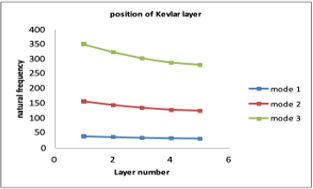
Figure 7 illustrates the impact of changing the Kevlar layer's position on the natural frequency. It was noted that the natural frequency decreases by changing the position of Kevlar fiber from the outer layer toward the laminate mid-ply. If the Kevlar layer is moved from the laminate's outside layer toward its middle ply, it was found that the natural frequency will decrease by 25%.
Figure 6. Effect of increasing the number of Kevlar layers on the natural frequency
Figure 7. Effect of Kevlar layer position
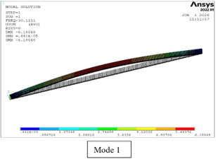
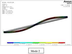
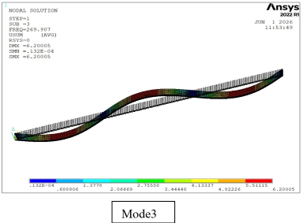
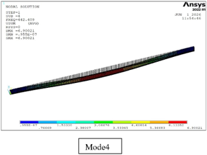
Correspondingly, Figure 8 presents the mode shapes together with the natural frequency of the [(G0)5]S configuration.
Figure 8. Mode shapes with natural frequencies
Table 5 presents the natural frequency of the hybrid laminated beams for the first three modes.
Table 5. Natural frequency (Hz) of the intact hybrid laminated beams for the first three modes
|
Configuration / Case |
Description |
Mode 1 (ωn1) |
Mode 2 (ωn2) |
Mode 3 (ωn3) |
|
[(G0)5]s |
Pure E-glass (base case) |
30.115 |
120.27 |
269.91 |
|
[k0/(G0)4]s |
2 Kevlar layers at top/bottom |
39.08 |
155.95 |
349.54 |
|
[(k0)2/(G0)3]s |
4 Kevlar layers |
44.684 |
178.22 |
399.09 |
|
[(k0)3/(G0)2]s |
6 Kevlar layers |
48.433 |
193.12 |
401.3 |
|
[(k0)4/G0]s |
8 Kevlar layers |
51.132 |
203.88 |
402.8 |
|
[(k0)5]s |
Pure Kevlar beam |
53.445 |
213.12 |
405.8 |
|
[G0/k0/(G0)3]s |
Kevlar layer shifted to the 2nd position |
36.143 |
144.26 |
323.43 |
|
[(G0)2/k0/(G0)2]s |
Kevlar layer shifted to the 3rd position |
33.774 |
134.84 |
302.43 |
|
[(G0)3/k0/G0]s |
Kevlar layer shifted to the 4th position |
32.098 |
128.18 |
287.6 |
|
[(G0)4/k0]s |
Kevlar layer shifted to the mid-plane |
31.226 |
124.71 |
279.8 |
4.2 Delamination effect
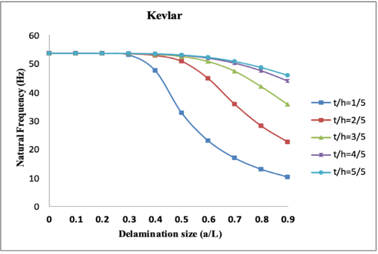
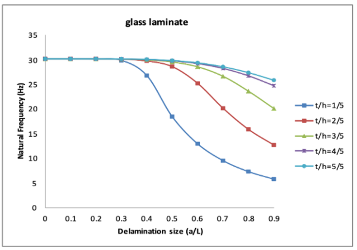
Two types of laminates are considered to comprehend how delamination affects the natural frequency of the unidirectional symmetric laminated composite beam. The first laminate was formed from Kevlar fiber, while the second was formed using glass fiber. Both these laminates contain delamination at different sizes and varying positions. The size of delamination (a/L) that was assumed in this study varied from 0 to 0.9, whereas the position of the delamination that was taken into account (t/h) varied from 0.1 to 0.5. The effect of delamination on the natural frequency of a laminated composite beam is shown in Figures 9 and 10, respectively.
Figure 9. Effect of delamination on natural frequency of Kevlar fiber composite laminated beam
Figure 10. Effect of delamination on natural frequency of glass fiber composite laminated beam
From the two figures, it can be noticed that there has been no appreciable change in the natural frequency for laminates that have delamination with sizes (a/L) ˂ 0.3 in all delamination positions. The effect of delamination begins at a size of delamination (a/L) ≥ 0.4 for near-surface delamination (t/h) = 0.1, while at (a/L) ≥ 0.5 for other positions. These two figures show that natural frequency decreases in the presence of delamination, especially at delamination length (a/L) ≥ 0.3, and the position of delamination has a significant effect, where a decrease in natural frequency is more pronounced in the case of near-surface delamination (t/h) = 0.1.
This can be justified by the change in the natural frequency, which is affected by the change in the elastic modulus, which is already influenced by fiber layer type, the stacking sequence, the direction of the fibers, the delamination length and its position. Numerical verification preceding the free vibration analysis demonstrated the accuracy of existing finite element processes. These results were compared with those obtained by Torabi [24], showing good agreement in terms of the natural frequency and delamination behavior.
Table 6 summarises the achieved results of the delamination grid for the pure E-glass beam [(G0)5]s (Mode 1 frequencies in Hz), or delamination grid mapping (a/L vs. t/h) and natural frequencies (Mode 1).
Table 6. Delamination grid mapping (a/L vs. t/h) and natural frequencies (Mode 1)
|
Thickness Ratio (t/h) |
1/5 |
2/5 |
3/5 |
4/5 |
5/5 |
|
a/L = 0 |
53.445 |
53.445 |
53.445 |
53.445 |
53.445 |
|
a/L = 0.1 |
53.444 |
53.444 |
53.445 |
53.444 |
53.444 |
|
a/L = 0.2 |
53.390 |
53.424 |
53.424 |
53.426 |
53.428 |
|
a/L = 0.3 |
52.894 |
52.277 |
53.357 |
53.386 |
53.394 |
|
a/L = 0.4 |
47.413 |
52.681 |
53.071 |
53.200 |
53.235 |
|
a/L = 0.5 |
32.638 |
50.631 |
52.300 |
52.722 |
52.829 |
|
a/L = 0.6 |
22.909 |
44.621 |
50.559 |
51.729 |
51.997 |
|
a/L = 0.7 |
16.894 |
35.674 |
47.158 |
49.985 |
50.569 |
|
a/L = 0.8 |
12.957 |
28.103 |
41.796 |
47.336 |
48.465 |
|
a/L = 0.9 |
10.247 |
22.487 |
35.593 |
43.787 |
45.753 |
This study investigated the effect of the length of delamination and the influence of Kevlar fiber on the natural frequency of a simply supported laminated composite beam. The main emphasis was on how natural frequency was affected by Kevlar fiber, delamination length, and delamination position. The following conclusions can be presented.
•While the magnitude of natural frequency increases with an increasing number of Kevlar layers, it is seen that there is no significant effect on the natural frequency of the laminate by increasing number of inner Kevlar fiber layers or replacing inner layers of glass fiber with Kevlar fiber.
•By changing the position of Kevlar fiber layer, the natural frequencies will change, where the natural frequency will decrease by shifting Kevlar fiber layer from near the surface to the mid-plane of the laminate.
•Laminated composite beams will have a higher natural frequency by 30% when the outer layer of glass fiber is replaced by Kevlar fiber layer, while the increasing of natural frequency will be 3% when the mid-plane layer is replaced.
•The natural frequency is reduced when there is delamination. Specifically, it is affected by the length of delamination; as the length of delamination increases, the natural frequencies decrease. It has also been noted that the position of delamination affects the natural frequency.
•There could be insignificant difference in the natural frequency of a laminated composite beam containing a small length of delamination (a/L ≤ 0.3) for all delamination positions. However, at longer delamination lengths, the influence of delamination position is clear.
•Near-surface delamination is more serious than mid-plane delamination, where the natural frequency of laminated composite beam decreased by 80% in the case of near-surface delamination (t/h = 0.1), while the decrease in natural frequency was 14% with regard to mid-plane delamination (t/h = 0.5) for the same size of delamination (a/L = 0.9).
|
A |
total cross-sectional area of the beam, m2 |
|
a |
delamination length, m |
|
b |
width of beam, m |
|
G |
modulus of rigidity, GN·m⁻² |
|
h |
height of beam, m |
|
k |
correction factor |
|
L |
length of beam, m |
|
M |
bending moment, N·m |
|
m |
number of layers |
|
n |
number of mode shapes |
|
t |
delamination depth, m |
|
V |
shear force, N |
|
E |
modulus of elasticity, GN·m⁻² |
|
I |
moment of inertia, m4 |
|
p |
angular frequency, Hz |
|
Greek symbols |
|
|
γ |
Slope of the deflection curve, rad |
|
φ |
Shear rotation angle, rad |
|
Ө |
Orientation angle of fiber, degree |
|
ρ |
Density, kg/m³ |
|
ω |
Frequency, rad·s-1 |
|
Subscripts |
|
|
ef |
effective |
|
n |
natural |
|
zd |
total delaminated |
|
d |
partial delaminated |
[1] Sabah Abdulmahdi, M. (2012). Effect of shear moduli and modular ratio (GF/GM) on the natural frequency of fiber reinforced composite rod under torsional free vibration. Al-Qadisiyah Journal for Engineering Sciences, 5(4): 407-423.
[2] Aydogdu, M. (2006). Comparison of various shear deformation theories for bending, buckling, and vibration of rectangular symmetric cross-ply plate with simply supported edges. Journal of Composite Materials, 40(23): 2143-2155. https://doi.org/10.1177/0021998306062313
[3] Ali, A.B.K. (2012). Analytical hand formula for member stiffness under clamped zone in bolted joints. Al-Qadisiyah Journal for Engineering Sciences, 5(2): 185-190.
[4] Jasem, M.H. (2012). Study the effect of the variation of layer's thickness on the bending characteristics of the composite beam. Al-Qadisiya Journal for Engineering Sciences, 5: 354-366.
[5] Abbas, A.M. (2019). Numerical investigation on the influence of web opening on the structural behaviour of RC deep beams. Al-Qadisiyah Journal for Engineering Sciences, 12(3): 178-183. https://doi.org/10.30772/qjes.v12i3.615
[6] Chandrasekar, M., Shahroze, R.M., Ishak, M.R., Saba, N., Jawaid, M., Senthilkumar, K., Senthil Muthu Kumar, T., Siengchin, S. (2019). Flax and sugar palm reinforced epoxy composites: Effect of hybridization on physical, mechanical, morphological and dynamic mechanical properties. Materials Research Express, 6: 105331. https://doi.org/10.1088/2053-1591/ab382c
[7] Mallick, P.K. (2007). Fiber-Reinforced Composites: Materials, Manufacturing, and Design. CRC Press.
[8] Dong, W., Li, W., Shen, L., Sun, Z., Sheng, D. (2020). Piezoresistivity of carbon nanotubes (CNT) reinforced cementitious composites under integrated cyclic compression and impact load. Composite Structures, 241: 112106. https://doi.org/10.1016/j.compstruct.2020.112106
[9] Jung, K.C., Han, M.G., Chang, S.H. (2020). Impact characterization of draped composite structures made of plain-weave carbon/epoxy prepregs utilizing smart grid fabric consisting of ferroelectric ribbon sensors. Composite Structures, 238: 111940. https://doi.org/10.1016/j.compstruct.2020.111940
[10] Yang, Z., Liu, J., Wang, F., Li, S., Feng, X. (2019). Effect of fiber hybridization on mechanical performances and impact behaviors of basalt fiber/UHMWPE fiber reinforced epoxy composites. Composite Structures, 229: 111434. https://doi.org/10.1016/j.compstruct.2019.111434
[11] Barouni, A.K., Dhakal, H.N. (2019). Damage investigation and assessment due to low-velocity impact on flax/glass hybrid composite plates. Composite Structures, 226: 111224. https://doi.org/10.1016/j.compstruct.2019.111224
[12] Julias, A.A., Mohmeed, S.A., Murali, V. (2014). Effect of delamination on buckling strength of unidirectional glass-carbon hybrid laminates. Indian Journal of Engineering and Materials Sciences, 21(1): 23-29. https://nopr.niscpr.res.in/handle/123456789/27446.
[13] Kakati, S., Chakraborty, D. (2020). Delamination in GLARE laminates under low velocity impact. Composite Structures, 240: 112083. https://doi.org/10.1016/j.compstruct.2020.112083
[14] Düring, D., Petersen, E., Stefaniak, D., Hühne, C. (2020). Damage resistance and low-velocity impact behaviour of hybrid composite laminates with multiple thin steel and elastomer layers. Composite Structures, 238: 111851. https://doi.org/10.1016/j.compstruct.2019.111851
[15] Della, N., Shu, D. (2007). Vibration of delaminated composite laminates: A review. Applied Mechanics Reviews, 60(1): 1-20. https://doi.org/10.1115/1.2375141
[16] Norman, M.M., Mahmud, J. (2021). Investigation of natural frequencies on Kevlar/Glass hybrid laminated composite plates using finite element simulation. International Transaction Journal of Engineering, Management, & Applied Sciences & Technologies, 12(9): 1-8. https://doi.org/10.14456/ITJEMAST.2021.169
[17] Erkliğ, A., Bulut, M., Yetr, E. (2015). The effect of hybridization and boundary conditions on damping and free vibration of composite plates. Science and Engineering of Composite Materials, 22(5): 565-571. https://doi.org/10.1515/secm-2014-0070
[18] Ma, Q., Merzuki, M.N.M., Rejab, M.R.M., Sani, M.S.M. (2022). Numerical investigation on free vibration analysis of Kevlar/Glass/Epoxy resin hybrid composite laminates. Malaysian Journal on Composites Science and Manufacturing, 9(1): 11-21. https://doi.org/10.37934/mjcsm.9.1.1121
[19] Prashanth, M.D., Basava, T. (2018). Vibration analysis of natural hybrid composites by experimental approach. IOP Conference Series: Materials Science and Engineering, 376(1): 012050. https://doi.org/10.1088/1757-899X/376/1/012050
[20] Nayak, P. (2008). Vibration analysis of woven fiber glass/epoxy composite plates. Master's thesis. National Institute of Technology Rourkela, India. https://www.yumpu.com/en/document/read/5251395/vibration-analysis-of-woven.
[21] Norman, M.A.M., Zainuddin, M.A., Mahmud, J. (2018). The effect of various fiber orientations and boundary conditions on natural frequencies of laminated composite beam. International Journal of Engineering & Technology, 7(3.11): 67-71. https://doi.org/10.14419/ijet.v7i3.11.15932
[22] Khider, N.S., Mostafa, A.M., Azeez, A.G. (2025). Empirical investigation of natural convection heat transfer from a horizontal cylinder fitted inside an enclosure of non-vertical adiabatic walls. Space, 129(2): 56-71. https://doi.org/10.37934/arfmts.129.2.5671
[23] Çallioğlu, H., Atlihan, G. (2011). Vibration analysis of delaminated composite beams using analytical and FEM models. Indian Journal of Engineering & Materials Sciences, 18(1): 7-14.
[24] Torabi, K., Shariati-Nia, M., Heidari-Rarani, M. (2016). Experimental and theoretical investigation on transverse vibration of delaminated cross-ply composite beams. International Journal of Mechanical Sciences, 115(4): 1-11. https://doi.org/10.1016/j.ijmecsci.2016.05.023
[25] Della, C.N., Shu, D. (2009). Free vibration analysis of multiple delaminated beams under axial compressive load. Journal of Reinforced Plastics and Composites, 28(11): 1365-1381. https://doi.org/10.1177/0731684408089503
[26] Imran, M., Khan, R., Rafiullah, S. (2019). Vibration analysis of cracked composite laminated plate: A review. Mehran University Research Journal of Engineering & Technology, 38(3): 705-716. https://doi.org/10.22581/muet1982.1903.14
[27] Weaver Jr, W., Timoshenko, S.P., Young, D.H. (1991). Vibration Problems in Engineering. John Wiley & Sons.
[28] Gibson, R.F. (2007). Principles of Composite Material Mechanics. CRC Press.
[29] Wang, J., Patil, M., Olortegui-Yume, J., Müller, N. (2010). Mechanical design of wound composite impeller using FEM. In 2010 ASME International Mechanical Engineering Congress and Exposition, Vancouver, British Columbia, Canada, pp. 195-201. https://doi.org/10.1115/IMECE2010-39762
[30] Abdel-Ghany, A.W., Taha, I., Ebeid, S.J. (2016). Failure prediction of fiber reinforced polymer pipes using FEA. International Journal of Engineering and Technical Research (IJETR), 4(2): 115.