Xuan Ngoc Nguyen![]() | Van Nhu Tran*
| Van Nhu Tran*![]() | Dang Thanh Mai
| Dang Thanh Mai![]() | Thanh Tam Tran
| Thanh Tam Tran![]()
© 2025 The authors. This article is published by IIETA and is licensed under the CC BY 4.0 license (http://creativecommons.org/licenses/by/4.0/).
OPEN ACCESS
The durability and structural integrity of clutch friction discs are critical to the reliability of automotive transmission systems, particularly under overload conditions. Among the primary geometric parameters influencing disc performance, the width of diagonal grooves plays a significant role in stress distribution and deformation behavior. In this study, the effect of groove width on the mechanical performance of a passenger vehicle clutch friction disc was systematically investigated. A three-dimensional model of the disc was constructed using Unigraphics NX, and numerical simulations were conducted via finite element analysis to evaluate stress, displacement, and safety factor by Ansys. Various groove widths were examined, with particular focus on a proposed configuration featuring a 3.5 mm wide diagonal groove. The simulation results indicated that this geometry yielded a maximum stress of 59.028 MPa, a total deformation of 0.027248 mm, and a minimum safety factor of 3.7932. These results demonstrate that the 3.5 mm groove width enables an effective balance between structural integrity and material efficiency, making it suitable for automotive applications where weight and manufacturing cost are constrained. The findings provide valuable insight for the structural optimization of clutch components and offer a reliable design reference for enhancing fatigue resistance under dynamic loading conditions.
friction disc, finite element, deformation, clutch disc groove, safety factor, Unigraphics NX, ANSYS
The friction disc is a part of the car clutch. The clutch plays a role in transmitting or disconnecting torque from the engine system to the transmission system through the friction disc because the friction disc meshes with the gearbox primary shaft. Therefore, manufacturers seek to make friction discs that ensure sufficient durability and reduce manufacturing costs. The choice of material, shape and size of the friction disc can significantly affect the performance of the system. The friction discs in clutch systems are usually made of wear-resistant and high-temperature-resistant materials. The design of the friction discs often has grooves and vents to enhance cooling and reduce wear during operation.
Many studies have investigated the materials, size parameters or thermal transformation of clutch friction discs to optimize the quality of the friction disc. Typically, Padmanabhan et al. [1] used FEM to analyze the effects of stress and temperature generated on the surface of dry clutch friction discs during operation for materials, including hard steel, sintered metal, and Kevlar, studying the application of SolidWorks and ANSYS for modeling and surveying. Similarly, Jabbar et al. [2] also used four types of materials to make friction linings for the clutch and employed ANSYS to analyze the temperature variation during the clutching process. The simulation showed that HCC and G95 materials were less heat resistant than other materials. Vo et al. [3] also used many different materials to make the friction layer, utilizing ANSYS to evaluate the temperature variations of the friction disc in operation. When using Kevlar material as the lining, the temperature at the friction surface increased less than the remaining materials, which reduced the risk of hardening the disc surface. Patil et al. [4] used CATIA to designed and built a three-dimensional clutch disc model of a passenger car and finite element analysis (FEA) by ANSYS to assess how material choice affects the structure, thermal resistance, and clutch disc formation, demonstrating that ceramic material exhibits less deformation compared to other materials. Virmani et al. [5] also studied ceramic material performance through stress and heat load using ANSYS. Depending on the type of vehicle or the size of the friction disc, many studies have examined various types of disc manufacturing materials. Bhoite [6] used FEM to analyze the structure of the clutch and employed ANSYS to simulate the tension and distortion of the friction disc. The results showed that ceramic is the best lining material compared to the five selected materials. Sahu [7] designed the single-disc clutch model using CATIA V5 software. The analysis using ANSYS showed that the aluminum metal matrix material is better than the remaining materials. Vardhan et al. [8] used non-ferrous materials to manufacture friction clutch discs and applied CATIA and ANSYS to analyze stress and deformation with operating conditions such as heat, dynamic, and static. Simulation showed that the aluminum alloy 6061 material is the most suitable. Xie et al. [9] used the nanomaterials to coat the clutch disc lining, aiming to predict the maximum stress in the design phase. CATIA and ANSYS were combined to model the clutch disc and analyze the thermal and structural factors to ensure service life. In addition, Rajan et al. [10] built a dual clutch model in the space of a passenger car and used CATIA to investigate the heat generation process when the car operates on a slope. The simulation results using Abaqus showed that the thermal stress was still within the allowable range. In the study of friction disc grooves, Ramesh et al. [11] used SolidWorks to design friction disc models with different groove types and then employed ANSYS to analyze the thermal finite element of those models corresponding to different types of friction materials. The results showed that the friction disc lining using organic materials is better than inorganic ones. Panchal et al. [12] even conducted a survey of the clutch on a motorcycle using a Continuously Variable Transmission (CVT) gearbox, testing measurements on two types of linings with and without grooves. The groove size was divided in proportion to the contact area of the disc surface. The roughness and thickness of the grooved disc decreased less by simulation results.
Most of the above studies focus on the research of materials for designing clutch friction discs. However, few studies have examined the impact of grooves on the friction discs. Although some studies [11, 12] have mentioned this part, the effect of groove size changes on the mechanical properties was not analyzed. Based on the function of the grooves on the car friction disc, if the grooves are too small, the heat dissipation will be poor. If the grooves are too large, the contact area of the disc surface will be small, making the disc easily warp and wear out faster. Therefore, this study examined the influence of groove width changes of the passenger car friction disc on deformation, stress and the safety factor of the disc. A three-dimensional model was built using Unigraphics NX and analyzed using ANSYS. Then an appropriate groove width size for manufacturing was proposed in this study.
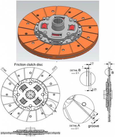
The groove on the friction disc has the function of venting and containing debris generated during the friction process. However, the groove cannot be designed too large, which will reduce the contact area of the disc surface, making the disc easily deformed and weak. This leads to clutch system slippage during gear shifting. If the groove is too small, poor ventilation can easily harden the contact surface. Although it has good bearing capacity, too much manufacturing material can be consumed. Therefore, it is necessary to have specific design parameters to ensure sufficient durability and reduction in expenses. Based on the configurations presented in the research by Ramesh et al. [11] and the actual clutch disc structure on passenger cars, Table 1 describes the fundamental dimensional characteristics of the friction disc.
Table 1. Basic specifications of the friction disc
|
Symbol |
Value |
Symbol |
Value |
|
T |
240.2 |
r0 |
272 |
|
n |
2 |
ri |
164 |
By applying Unigraphics NX, the friction disc 3D model was created, as depicted in Figure 1. This software has been widely used in simulating mechanical test specimens [13].
Figure 1. Clutch disc design model
Before conducting FEA on the friction disc, the pressure exerted on the disc surface must be established. As indicated by the research results from several studies [14, 15], the pressure and total force applied to the friction disc were calculated as follows:
According to the uniform pressure, the effective radius of friction and the total force acting on the disc were determined as follows:
${{R}_{P}}=\frac{2({{r}_{0}}^{3}-{{r}^{3}}_{i})}{3({{r}_{0}}^{2}-{{r}_{i}}^{2})}$ (1)
${{\text{W}}_{P}}=\frac{T}{\mu *n*{{R}_{P}}}$ (2)
The friction coefficient of the gray cast iron material [16] proposed by Özokutgen and Okur [17] is µ = 0.28.
The pressure acting on the disc was calculated as follows:
${{P}_{P}}=\frac{{{\text{W}}_{P}}}{\pi .({{r}_{0}}^{2}-{{r}_{i}}^{2})}$ (3)
According to the uniform wear, the radius of friction, the total force acting and the pressure acting on the disc were determined as follows:
${{R}_{\text{W}}}=\frac{{{r}_{0}}+{{r}_{1}}}{2}$ (4)
${{\text{W}}_{\text{W}}}=\frac{T}{\mu *n*{{R}_{\text{W}}}}$ (5)
The pressure acting on the disc was calculated as follows:
${{P}_{\text{Wmax}}}=\frac{{{\text{W}}_{\text{W}}}}{2\pi .({{r}_{0}}-{{r}_{i}}){{r}_{i}}}$ (6)
${{P}_{\text{Wmin}}}=\frac{{{\text{W}}_{\text{W}}}}{2\pi .({{r}_{0}}-{{r}_{i}}){{r}_{0}}}$ (7)
${{P}_{\text{Wtb}}}=\frac{{{\text{W}}_{\text{W}}}}{\pi .({{r}_{0}}^{2}-{{r}_{i}}^{2})}$ (8)
Table 2 displayed the results of the calculated values from the equations.
Table 2. Results of force and pressure acting on the clutch friction disc
|
Symbol |
Value |
Symbol |
Value |
|
RP |
0.111 |
WW |
3935.12 |
|
WP |
3864.22 |
PWmax |
0.141 |
|
PP |
0.104 |
PWmin |
0.0853 |
|
RW |
0.109 |
PWtb |
0.106 |
For used components, the theory of uniform wear is often applied because the force acting on it is not evenly distributed. The theory of uniform pressure is used for new products similar to some studies [3, 6, 17, 18]. Therefore, the uniform pressure was used for simulation in this study.
In the design of pressure-bearing parts, the final structural parameters need to be re-examined due to the influence of factors such as load, stress, deformation, and failure limit. These technical problems are often solved by mathematical methods to ensure that the systems are durable enough during their operation. However, for complex parts, software tools are often used for FEA, similar to some studies [19, 20]. The ANSYS software was used in this study to solve that problem.
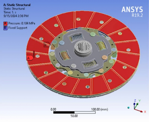
Before analysis, it is necessary to mesh the three-dimensional model so that the complex positions of the clutch friction disc are considered and calculated by the software, which can create a meshed model after implementation [21, 22]. In addition, it is necessary to apply uniform pressure, as illustrated in Figure 2, to observe the disc's changes as the simulation.
The meshing model in Figure 2 uses a tetrahedron mesh with 2,610,680 nodes and 1,302,454 elements distributed on the vehicle friction disc. The friction disc, also known as the clutch disc, based on its function, operating principle and location on the car, shows that the clutch disc is only directly affected by the pressure plate of the clutch pressing against the engine flywheel. Therefore, the pressure applied to the friction disc is 0.104 MPa. FEA of the clutch friction disc was conducted when the groove widths (TGW) on the disc are 2.0, 2.5, 3.0, 3.5, and 4.0 mm, respectively, to consider the stress and deformation of the disc as follows.
Figure 2. Meshing model and pressure acting on the friction disc
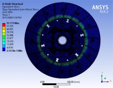
Figure 3. Stress and deformation of the clutch friction disc with TGW of 2.0 mm
For TGW of 2.0 mm, Figure 3 shows that the stress is 57.773 MPa, and the strain is 0.026649 mm.
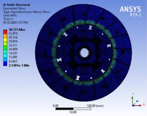
Figure 4. Stress and deformation of the clutch friction disc with TGW of 2.5 mm
For TGW of 2.5 mm, Figure 4 shows that the stress is 58.521 MPa, and the strain is 0.026844 mm.
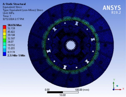
Figure 5. Stress and deformation of the clutch friction disc with TGW of 3.0 mm
For TGW of 3.0 mm, Figure 5 shows that the stress is 58.656 MPa, and the strain is 0.027025 mm.
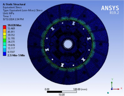
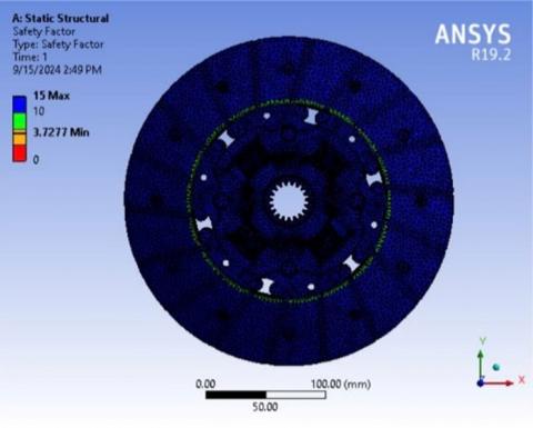
Figure 6. Stress and deformation of the clutch friction disc with TGW of 3.5 mm
For TGW of 3.5 mm, Figure 6 shows that the stress is 59.028 MPa, and the strain is 0.027248 mm.
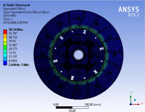
Figure 7. Stress and deformation of the clutch friction disc with TGW of 4.0 mm
a) TGW of 2.0 mm
b) TGW of 2.5 mm
c) TGW of 3.0 mm
d) TGW of 3.5 mm
e) Groove width of 4.0 mm
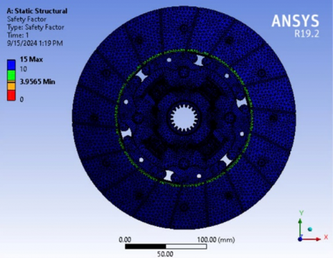
Figure 8. Results of the safety factor for varying widths of clutch disc grooves
For TGW of 4.0 mm, Figure 7 indicates a stress of 59.34 MPa, a strain of 0.027482 mm.
Comparing the simulation outcomes from Figures 3 to 7, it is determined that for all cases of groove widths on the clutch friction disc, the stress is most concentrated right at the circle with the inner radius because this part is very little connected to the iron frame inside the friction disc. As the radius of the friction disc gradually increases to the outer diameter, the stress gradually stabilizes (all are covered in blue) because this part is tightly connected. In the case of a groove width of 4.0 mm, the stress reaches the maximum value of 59.34 MPa, and the maximum deformation is 0.027482 mm. On the contrary, in the case of a groove width of 2.0 mm, the stress and deformation reach the minimum values of 57.773 MPa and 0.026649 mm, respectively. However, it is still not possible to determine which design parameters are the best because in the manufacturing process, the safety factor of the manufacturing materials must also be considered to ensure that they meet the standards, as stated in the study by Ramli et al. [23] of at least 1.2.
The results in Figure 8 show that all cases ensure the safety factor. The highest value is in the case of TGW of 2.0 mm, with TGW of 4.0 being the lowest safety factor value. The data is compiled in Table 3.
Table 3. Values of stress, deformation and the safety factor of the clutch friction disc
|
Groove Width (mm) |
Stress (MPa) |
Deformation (mm) |
Safety Factor |
|
2.0 |
57.773 |
0.026649 |
3.9565 |
|
2.5 |
58.521 |
0.026844 |
3.9223 |
|
3.0 |
58.656 |
0.027025 |
3.8048 |
|
3.5 |
59.028 |
0.027248 |
3.7932 |
|
4.0 |
59.34 |
0.027482 |
3.7277 |
Based on the statistical results in Table 3, it is determined that if the design parameter is 4.0 mm, the maximum stress reaches the highest value, the largest deformation and the lowest safety factor. If the value is 2.0 mm, on the contrary, the stress is low, the deformation is small and the safety factor is high. This shows that the groove width is proportional to the stress and deformation, and inversely proportional to the safety factor. When the groove width increases, the contact area of the disc surface will decrease, the force acting directly on the disc will make the disc easily warped, and the disc is easily destroyed. Therefore, the safety factor will decrease. The decrease in the groove width leads to difficult ventilation, the disc surface is easy to harden, and the material of the friction surface increases, which increases the amount of materials. Therefore, choosing the groove size to avoid too much deformation and too large a safety factor can lead to high manufacturing costs. In general, the results determine that the values ensuring the durability are almost the same. Therefore, it is necessary to choose the safety factor so that when manufacturing, it can reduce the cost as much as previous studies [16, 23]. Thus, TGW of 3.0 mm was proposed as the optimal design parameter for the clutch friction disc in this study.
The basic parameters for the design of the friction disc groove were determined in this study. This result is based on FEM analysis of the clutch disc when changing the groove width from 2.0, 2.5, 3.0, 3.5, to 4.0 mm. The spatial model of the clutch friction disc was performed under static conditions to calculate the factors related to the durability of the disc. The objective of this study is to propose the best groove width size of 3.0 mm to ensure durability and reduce the cost of manufacturing the clutch friction disc. Friction discs are widely used in automobiles; determining specific parameters and limiting the use of many materials can help businesses save a lot of costs and improve manufacturing efficiency. This can be applied in the mass production of clutch friction discs at factories.
|
T |
The friction torque, N.m |
|
n |
Number of contact surfaces of the disc |
|
r(o,i) |
Corresponds to the outer and inner radius of the clutch friction disc, m |
|
R(p,w) |
Corresponds to the effective mean radius of the disc in the case of uniform pressure and wear, m |
|
W(p,w) |
Corresponds to the pressure acting on the disc in the case of uniform pressure and wear, N |
|
Pp |
Pressure acting in the case of uniform pressure, N.mm-2 |
|
P(Wmax,Wmin,Wtb) |
Corresponds to the maximum, minimum and average pressure in the case of uniform wear, N.mm-2 |
|
Greek symbols |
|
|
µ |
Coefficient of friction of gray cast iron |
[1] Padmanabhan, S., Kumar, T.V., Kumar, D.S., Velmurugan, G., Kumar, B.A., Subramanyam, K.H.S. (2023). Investigation of structural and thermal analysis of clutch facings with different friction materials. Materials Today: Proceedings, 92: 98-105. https://doi.org/10.1016/j.matpr.2023.03.757
[2] Jabbar, N.A., Hussian, I.Y., Abdullah, O.I. (2023). Numerical simulation of dry friction clutch thermal behavior with different friction materials. In AIP Conference Proceedings, Baghdad, Iraq, p. 050005. https://doi.org/10.1063/5.0105422
[3] Vo, L.K.T., Nguyen, X.N., Nguyen, B.L., Tran, T.T. (2023). Analysis of the Effect of materials on the thermal change of the clutch friction disc. In The International Conference on Sustainable Energy Technologies, Singapore, pp. 495-503. https://doi.org/10.1007/978-981-97-1868-9_50
[4] Patil, K.K., Randive, V., Mulla, S., Parit, R., Mane, S., Kadam, S. (2020). Design and analysis of single plate clutch by mathematical modelling and simulation. International Journal of Advance Research and Innovation, 8(3): 248-252.
[5] Virmani, K., Madhogaria, T., Baskar, P. (2021). Design optimization of friction lining of a clutch plate. Materials Today: Proceedings, 46: 8009-8024. https://doi.org/10.1016/j.matpr.2021.02.775
[6] Bhoite, S.J. (2022). Design and analysis of single plate friction clutch. International Journal of Innovative Research in Technology, 8(9): 199-206.
[7] Sahu, M. (2018). Finite element analysis of single plate clutch by using ANSYS. International Journal for Research in Applied Science and Engineering Technology, 6(6): 1337-1346. https://doi.org/10.22214/ijraset.2018.6195
[8] Vardhan, M.V., Narendra, T.S., Ajay, K., Dhanraj, B., Kumar, C.A. (2023). Design and analysis of single plate clutch by using non-ferrous materials. Materials Today: Proceedings, 92: 478-489. https://doi.org/10.1016/j.matpr.2023.03.596
[9] Xie, C., Wu, G., He, S., Zhang, Y., Tian, J. (2021). Finite element analysis of thermal load characteristics of dry dual clutch. In Journal of Physics: Conference Series, Shenyang, China, p. 052047. https://doi.org/10.1088/1742-6596/1748/5/052047
[10] Rajan, B.G., Padmanabhan, S., Prathap, K.M., Prasad, U.S., Kumar, G.P. (2022). Investigation on mechanical behaviour of single plate clutch with nano coating through FEA. Materials Today: Proceedings, 59: 1394-1406. https://doi.org/10.1016/j.matpr.2021.12.102
[11] Ramesh, M.R., Ravindra, K.A., Ashok, B., Kannan, C. (2021). Optimizing thermal performance of a dry rigid clutch by varying groove pattern and friction material. Materials Today: Proceedings, 46: 7459-7467. https://doi.org/10.1016/j.matpr.2021.01.130
[12] Panchal, D., Patel, B., Gohil, H. (2023). Experimental investigation on performance characteristics of dry centrifugal clutch with grooved friction liners. International Journal of Automotive and Mechanical Engineering, 20(1): 10152-10164. https://doi.org/10.15282/ijame.20.1.2023.01.0786
[13] Mao, H., Wang, Y., Yang, D. (2022). Study of injection molding process simulation and mold design of automotive back door panel. Journal of Mechanical Science and Technology, 36(5): 2331-2344. https://doi.org/10.1007/s12206-022-0415-0
[14] Narayan, S., Grujic, I., Stojanovic, N., Usman, K.M., Shitu, A., Mahroogi, F.O. (2018). Design and analysis of an automotive single plate clutch. Mobility & Vehicle Mechanics, 44(1): 13-26. https://doi.org/10.24874/mvm.2018.44.01.02
[15] Patil, K.K., Randiv, V., Mulla, S., Parit, R., Mane, S., Kadam, S. (2020). Design and analysis of single plate clutch using ANSYS. Mobility and Vehicle Mechanics, 46(2): 19-31. https://doi.org/10.24874/mvm.2020.46.02.02
[16] Nguyen, X.N., Dang, T.P., Vo, K.D., Tran, T.T. (2024). Influence of material properties on the durability of automotive hydraulic brake discs: A finite element analysis approach. Revue des Composites et des Materiaux Avances, 34(6): 767-773. https://doi.org/10.18280/rcma.340611
[17] Ozokutgen, R., Okur, M. (2021). Analysis of contact material of single friction plate in clutch system. Engineering and Educational Technologies, 2021(1): 47-53. https://avesis.gazi.edu.tr/yayin/b3f0c1b2-0e94-433b-9900-fba286d4cd71/analysis-of-contact-material-of-single-friction-plate-in-clutch-system.
[18] Ali, I.A., Asiri, S. (2022). Thermal and mechanical analyses of dry clutch disk made of functionally graded aluminum matrix composite. Materials Research Express, 9(4): 046507. https://doi.org/10.1088/2053-1591/ac6150
[19] Chan, T.C., Ullah, A., Roy, B., Chang, S.L. (2023). Finite element analysis and structure optimization of a gantry-type high-precision machine tool. Scientific Reports, 13(1): 13006. https://doi.org/10.1038/s41598-023-40214-5
[20] Shahzamanian, M.M., Partovi, A., Wu, P.D. (2020). Finite element analysis of elastic–plastic and fracture behavior in functionally graded materials (FGMs). SN Applied Sciences, 2: 1-11. https://doi.org/10.1007/s42452-020-03901-w
[21] Ferrak, A.E.H., Manaa, R., Faiza, K. (2024). Thermomechanical analysis of a gas turbine blade in composite materials with a ceramic (Al2O3) coated. Revue des Composites et des Matériaux Avancés-Journal of Composite and Advanced Materials, 34(3): 331-338. https://doi.org/10.18280/rcma.340308
[22] Jumaah, O.D., Hamid, A.A., Younis, A.D. (2024). Numerical evaluation of porous structure of titanium alloy fabricated via selective laser melting (SLM) process. Revue des Composites et des Matériaux Avancés-Journal of Composite and Advanced Materials, 34(5): 573-579. https://doi.org/10.18280/rcma.340505
[23] Ramli, M.N., Sulaiman, S., Azizul, M.A. (2020). Implementation of weight reduction method for lower front control arm without reducing the safety factor. Journal of Design for Sustainable and Environment, 2(2). https://jdse.fazpublishing.com/index.php/jdse/article/view/22.