Feifei Zhao
© 2021 IIETA. This article is published by IIETA and is licensed under the CC BY 4.0 license (http://creativecommons.org/licenses/by/4.0/).
OPEN ACCESS
In actual engineering, the drive axle of vehicles is often enlarged to prevent it from being damaged. However, the enlargement will increase the weight of the vehicle, pushing up fuel consumption and exhaust emissions. This common practice is obviously detrimental to the environment and sustainable development. To meet the stiffness and strength requirements on the drive axle housing of Steyr heavy trucks, this paper carries out finite-element analysis on the stiffness and strength of the axile housing under different working conditions, in the light of its actual stress features. According to the production process of drive axle housing in truck, the authors reviewed the development of the materials for high-strength axle housing, which could be properly formed through hot stamping, cold stamping, and mechanical expansion, and briefly introduced the structural features of drive axle housing. Then, a drive axle model was established in the three-dimensional (3D) drawing software Pro/ENGINEER, and converted into a finite-element model in Pro/Mechanica by calling the meshing command. On this basis, the static load of axle housing was analyzed under four working conditions: maximum vertical force, maximum traction, maximum braking force, and maximum lateral force. Finite-element analysis was performed on the meshed model to obtain the displacement and stress cloud maps of the axle housing under each working condition. The results show that the drive axle housing satisfy the requirements on strength, stiffness, and deformation. To sum up, this research improves the design efficiency and quality of products through finite-element analysis on the stiffness and strength of drive axle housing.
drive axal housing, stress analysis, deformation analysis, lightweight steel, finite-element analysis
With a complex structure, drive axle housing needs to adapt to various driving conditions. Therefore, the stress on the main points of the housing is conventionally calculated by empirical or semi-empirical formulas, which are not very accurate. Meanwhile, the strength, stiffness, and fatigue life of drive axle housing are traditionally measured through bench test or road test on the whole vehicle. The traditional approach is both time consuming and labor intensive.
With the continuous development of the finite-element analysis, it is now relatively easy to perform finite-element analysis on the drive axle housing of vehicles, and thus acquire the design and analytical data on the static force, dynamic force, fatigue life, and optimal structure. Under this premise, many scholars at home and abroad have explored the structure of rear axle housing, and drawn important conclusions. The domestic and foreign research on finite-element analysis of axle housing is summarized as follows:
Heidsieck and Wallgren [1] established a modular rear axle drive system, demonstrated the working mode of modular rear axle system, and discussed the control of multi-function operations of the modularized rear axle. Firat [2] simulated the rear axle bending fatigue by fatigue software, and identified the cracking positions of rear axle. Kepka and Kepka Jr [3-6] measured the time history of critical sectional stress at the weld of rear axle housing, derived the fatigue life of rear axle housing, and verified the result with the distribution function. Xu et al. [7] simulated and tested the key formation process of 5T seamless steel pipe drive axle housing, and verified the feasibility of the material from both theory and practice; in this way, Xu provided a novel manufacturing technique for monolithic drive axle housing, which greatly improves the manufacturing level of this type of products.
Since the early 1960s, finite-element analysis has been in use for more than six decades. However, China is a late starter in finite-element analysis. The application of this technique is not yet mature domestically. Some Chinese scholars have performed finite-element analysis on drive axle housing:
In 2018, Cui [8] conducted finite-element analysis on the steering drive axle housing of light trucks, and obtained the cloud maps on the stress and displacement at main positions; then, optimization was carried out to reduce the weight of axle housing, without affecting the overall performance. In the same year, Li [9] performed finite-element analysis and fatigue life analysis of the drive axle of loader, and implemented three-dimensional (3D) modeling and finite-element static analysis on Pro/ENGINEER and ANSYS, respectively, revealing the static strength and static stiffness of the axle housing under each working condition; then, the critical cross-section was located by analyzing the stress and displacement changes at each position, and the life of axle housing was estimated on nCode DesignLife, drawing on Miner’s linear damage rule.
Reducing vehicle weight is the most effective measure to reduce energy consumption and control exhaust emissions. The lightweight design both lowers the vehicle weight, and saves raw materials. More importantly, this approach can decrease the production cost of vehicles. The key to lightweight design is to reduce the weight of chassis. Many researchers are paying attention to the lightweight design of the axle housing, the main carrier of vehicle load.
There are two paths for lightweight design: (1) Optimize the design of steel structure and pattern, and reduce mass while ensuring comfort and load capacity; (2) Reduce the mass by replacing steel with low-density materials like modern composites and light metals. Currently, the main foreign methods for lightweight design of vehicles include:
(1) Resort to cutting-edge manufacturing machines and a complete set of manufacturing processes. The cutting-edge manufacturing machines can greatly increase the processing accuracy of each part of the vehicle, while the complete set of manufacturing processes can minimize the manufacturing deviations, making it possible to improve and optimize the size of each part [10, 11].
(2) Adopt advanced approaches and novel optimization algorithms. For lightweight design of vehicles, foreign researchers have presented topology optimization algorithms, and structural optimization concepts, and combined them with finite-element analysis [12].
(3) Implement dynamic simulation and physical test. The collision and vibration of each part are simulated, and the reliability of the results is verified through experiments, thereby producing the new structure that meets the design requirements [13, 14].
(4) Select lightweight materials. During vehicle manufacturing, lightweight materials are adopted for the parts in specific structures, which cuts down the vehicle weight and gives birth to a new structure.
In recent years, Chinese automotive researchers also carried out lots of tests on vehicle lightweight design. Shandong University, in association with Shandong Wuzheng Group Co., Ltd., studied the lightweight design of drive axle for light trucks, while Anhui University of Science and Technology explored the lightweight design of the drive axle for heavy trucks. Both projects are about the cross-disciplinary structural optimization of rear drive axle assembly. In addition, Anhui University of Science and Technology launched the multi-objective optimization of the lightweight design of cast steel drive axle housing of heavy self-unloading trucks, and pursued the lightweight design by combining structural optimization of topology, shape, and size. These three projects all focus on the structural optimization of the rear drive axle assembly.
Overall, the domestic research on vehicle lightweight design still lags far behind the foreign research. The main shortcomings include the lack of advanced design philosophy and motivation for new technology development, the overreliance on empirical manufacturing, and the insufficient use of lightweight materials.
Targeting the drive axle housing of Steyr heavy trucks, this paper introduces a series of lightweight high strength steels for axle housing under different manufacturing processes of truck drive axle housing, and realizes the lightweight design of axle housing. After analyzing the stress features of rear axle housing, the authors calculated the stress state of rear axle housing under each working condition. Then, a drive axle model was established on the 3D drawing software Pro/ENGINEER, and simplified for finite-element modeling. On Pro/Mechanica, the unit and material properties of rear axle housing were selected, and the rear axle housing was meshed to obtain a finite-element model. Considering the force state of drive axle housing under each working condition, the authors carried out the finite-element analysis and static analysis on drive axle housing, verified whether the strength and stiffness meet requirements with cloud maps on stress and displacement, and deduced the material redundancy of axle housing.
Through this research, a standardized procedure was obtained for the finite-element modeling of drive axle housing, laying the basis for applying finite-element analysis on drive axle housing design. The dynamic and static features of drive axle housing were analyzed to provide theoretical support to the deformation design of drive axle housing. The structural optimization of drive axle housing was discussed preliminarily, and the optimal design was tentatively applied to drive axle housing design, paving the way for subsequent axle housing design.
The research helps automotive enterprises to handle problems in actual production, and provides them with best practices in product design, manufacturing, inspection, and optimization. More importantly, our strategy can greatly lower the production cost of vehicles. Following our strategy, automotive enterprises could improve the product design and quality, enhance their core competitiveness, and achieve a marked growth of economic income.
After the enforcement of Limits and Measurement Methods for Emissions from Diesel Fueled Heavy-Duty Vehicles (China VI) and strict penalization on overload and overrun, it is an inevitable trend to reduce the weight of heavy commercial vehicles. Estimation shows that, if a vehicle is 100kg lighter, it will consume 0.5L fewer fuel, and emit 12g less carbon dioxide per 100km. In fact, drive axle is an unsprung mass. According to industry experience, every 1kg reduction in unsprung mass is equivalent to a 15kg reduction in sprung mass.
There are various techniques to manufacture drive axle housing, including casting, stamping-welding, and mechanical expansion. The traditional casting technique has been largely replaced by stamping and mechanical expansion, because of its high cost, complex process, heavy housing, energy inefficiency, and environmental unfriendliness [15]. In China, the 13t stamped drive axle housing is mainly formed by hot stamping, using 14-16mm thick Q345B or Q460C steel sheets. The mechanically expanded axle housings are mostly made of Q345B or 20Mn2 seamless steel pipes, which are 14-16mm thick.
There is a remarkable gap between China and foreign countries in the lightweight design of axle housing. For example, MAN Truck & Bus of Germany produces drive axle housing with high-strength steels, whose yield strength is 500MPa and tensile strength is 600MPa; the 13t drive axle housing produced by hot stamping is only 11-12mm in thickness.
To meet the demand of automotive enterprises for lightweight and durable axle housing, steel enterprises are striving to develop even stronger steels for axle housing. For instance, Shougang Group Co., Ltd. developed a series of light high-strength axle housing steels, which can be formed by hot stamping, cold stamping, and mechanical expansion [16-20]. Currently, the axle housing steels with strength of 700MPa and below can be mass-produced in China.
(1) Hot stamped axle housing steels
For 13t and above drive axle housing of heavy trucks, hot stamped [17] axle housing steels must have good stiffness and static strength. To prevent cracking, the axle housing needs to be hot stamped from 14-20mm thick steel sheets [18]. Specifically, the steel sheets are inductively heated to 800-900℃, stamped into the shape of axle housing under the temperature range, and then cooled in the air [19].
At present, the high-strength steel sheets for hot stamped axle housing are mostly Q460C steel. After hot stamping, the axle housing is required to maintain the mechanical performance of Q460C steel. However, the Q460C steels produced by different plants vary significantly in components and processes. The hot-stamped axle housing might have problems like performance fluctuation and low strength, which will affect the housing life.
To ensure the high strength of hot-stamped axle housing, Shougang Group Co., Ltd. developed an axle housing steel, whose yield strength is 420-550MPa after hot stamping, and successfully tried the steel in rear drive axle housing of commercial vehicles. Considering the impact of the user heating process on material performance, the company adopts the design philosophy of medium carbon-low manganese-trace alloy elements (Ti, Nb, and V), and guarantees the performance of hot-stamped materials through solution strengthening, fine crystal strengthening, and precipitation strengthening.
Shougang Group Co., Ltd. also developed the SQ500RQK steel with the C-Mn-Ti-Nb component system. Low temperature finish rolling is coupled with high temperature coiling to obtain fine ferrite and (Ti, Nb)C precipitation phase. The 12mm thick rolled steel sheets are inductively heated to 800°C to reach the yield strength of 553 MPa, the tensile strength of 623 MPa, and the elongation after fracture of 32%. This steel can replace 14mm thick Q345B or Q460C steel sheets to achieve lightweight design of axle housing.
(2) Cold stamped axle housing steels
For the lightweight design of axle housing, Shougang Group Co., Ltd. developed a series of cold-stamped axle housing steels. These steels are produced under the low C-Mn-Nb/V component system, with strict control of the content of elements like P, S, and N. This ensures the high strength, good plasticity, and low yield ratio of the material. The cold-stamped steels are made of ferrite and a small amount of pearlite.
The SQ550LQK steel sheets developed by Shougang Group Co., Ltd. is 6-14mm thick, using the C-Mn-NB-Cr-V component system. The 12mm thick axle housing steel is manufactured under controlled rolling and controlled cooling. Its yield strength is 587MPa, tensile strength is 673MPa, elongation after fracture is 23%, and strip tissue is ≤1.5 level. Cold bending and folding tests show that no visible crack is observable at the bending place of the 12mm thick steel plate, an evidence of good forming performance.
(3) Mechanically expanded axle housing steels
Mechanical expansion as a forming technique has long been available. However, this technique was not applied to automotive manufacturing until the 1990s, with the development of vehicle stamping. XCMG is the first Chinese enterprise to produce drive axle housing through mechanical expansion, by introducing the expansion forming technique of SOMAB, France. Currently, the mainstream mechanical expansion is hot mechanical expansion, which heats Q345B or 20Mn2 seamless steel pipes (wall thickness: 14-16mm) to ≥850℃.
To lower the production cost of mechanically expanded axle housing, Shougang Group Co., Ltd. designed a string of low yield ratio steels for cold mechanically expanded axle housing. For example, the mechanically expanded axle housing could adopt 12mm thick SQK750ZX steel sheets, which are known for excellent hot rolling performance. The weld pipe produced by high-frequency resistance welding can be used for cold mechanical expansion of axle housing. After thermal refining, the yield strength can reach 689MPa, the tensile strength, 773MPa, and the elongation after fracture, 26%. The weld pipe can replace 14mm seamless pipe, eliminate the heating process of expansion forming, and reduce the weight of the axle housing, making the manufacturing process more energy efficient.
3.1 Analysis of drive axle housing design
3.1.1 Classification and features of drive axle housing
Drive axle housing can be divided into separable axle housing, integral axle housing, and combined axle housing. The separable axle housing generally has two, three, or even more segments, which are connected by bolt. Two-segment axle housing is mainly composed of bolt-connected casting parts: main reducer housing, housing cover, flange, and half-axle sleeve. The separable axle housing is easy to manufacture. Besides, the bearing of the main decelerator boats a good stiffness. However, this type of axle housing is rarely adopted, because it is poor in strength and stiffness, and the main decelerator is not easy to assemble, adjust, and maintain.
The integral axle housing is a complete whole. Like a hollow beam, this type of axle housing has good strength and stiffness. The axle housing and main decelerator housing are arranged in two parts. The gear and differential mechanism are both deployed in an independent housing, forming a separate assembly. After being adjusted, the assembly is installed in the middle to front section of axle housing, and bolted with the axle housing. As a result, the main decelerator and differential mechanism could be conveniently disassembled, adjusted, maintained, and repaired. Figure 1 shows the integral casting axle housing, one of the four kinds of integral axle housing. The other three types are stamped and welded from steel plates, expanded from steel pipes, and manufactured through liquid expansion.
Combined axle housing is also known as support axle housing. The casting main decelerator is placed at the center of axle housing, and seamless steel pipes are pressed to the two ends of the decelerator, and then fixed with pins or plug welding. Combined axle housing enjoys highly stiff bearing housing and a low weight, but requires a high machining accuracy [21].
3.1.2 Design analysis of drive axle housing
This paper mainly carries out stress analysis on integral drive axle housing, and calculates its strength based on its cross-sectional dimensions. As a main bearing member of the vehicle, ccc axle housing has very complex shapes. But the driving conditions (e.g., road conditions, climate, and travel conditions) are highly changeable. Thus, it is very difficult to compute the stress state on each part of axle housing in the course of driving.
1. Rear axle housing; 2. Differential mechanism housing; 3. Planetary gear of differential mechanism; 4. Half-axle gear of differential mechanism; 5. Half-axle; 6. Driven gear ring of main decelerator; 7. Driving pinion of main decelerator
Figure 1. Integral drive axle housing
In the past, China mainly evaluated the strength and stiffness of axle housing through bench test and road test on whole vehicle. Sometimes, the stress on axle housing is measured by pasting strain gages on axle housing, and driving the fully-loaded vehicle on a typical road section.
The above methods only work when axle housing samples are available, and consume considerable manpower, material, and time. Through elastic mechanics, Isuzu calculated the stress and deformation of axle housing by neglecting the back cover of axle housing and simplifying the convex for the main decelerator at the middle of the axle housing as a regular ring. Despite the precision of elastic mechanics, the calculation accuracy is undermined by the over-simplification of the geometry of axle housing.
In general, axle housing is mostly designed by conventional methods: the axle housing is viewed as a simply supported beam, and the maximum stress on a specific cross-section is calibrated. Some Japanese companies require that the drive axle housing to meet the following design standard: under 2.5 times of full-load axial load, the stress on each cross-section (spring seat, weld between axle housing and half-axle sleeve, and round corner at the root of bearing in the hub) should not exceed the yield limit.
China recommends to simplify the complex stress state on axle housing into three typical conditions:
(1) When the fully loaded vehicle travels through uneven pavement, the wheels are subjected to the maximum vertical force;
(2) When the fully loaded vehicle transmits the maximum traction or emergency braking force, the wheels are subjected to the maximum tangent force;
(3) When the fully loaded vehicle sideslips, the wheels are subjected to maximum lateral force.
Under these three typical conditions, the axle housing is reliable under various driving conditions, as long as the axle housing has sufficient strength.
The above conventional calculation method for axle housing strength can merely approximate the mean stress of a cross-section of axle housing, failing to fully reveal the stress and its distribution of axle housing. Therefore, this method only applies to computing the strength of axle housing, or comparing the axle housing strengths of various vehicles. It is impossible to find the actual stress on any point (e.g., stress concentration point) of axle housing.
Finite-element method is a modern calculation method for complex structures. Capable of simulating the actual shape, structure, forces, and constraints of components, this approach can pinpoint the stress and strain in any geometric part of various mechanical parts and components. Around the 1970s, finite-element method was gradually applied to analyze the axle housing strength of vehicles in foreign countries. For example, International Trucks resorted to finite-element method to compute the axle housing strength.
When finite-element method is applied to analyze the strength of drive axle housing, it is possible to obtain desirable results, provided that the calculation model is properly simplified, and the force and constraint conditions are applied appropriately. In addition, this method can acquire detailed distribution of stress and deformation, and ascertain the stress concentration area and stress trend. These are not easy to realize by any conventional approach.
3.2 Finite-element modeling and preprocessing
The finite-element modeling must reflect the key mechanical features of the object, simplify unit morphology, and minimize the number of units. The purpose is to obtain high calculation accuracy, save computing time, and avoid unnecessary waste. Therefore, it is necessary to simplify non-carriers and secondary non-hazardous structures, while retaining the original structure of main carriers, such that the model can reflect the main features and mechanical properties of the actual structure. As a result, the following simplifications should be performed on the structure during modeling, while ensuring the correctness of the model, the relevance between geometric elements, and the stability of mechanical properties:
(l) The fine parts like welds and threaded holes might increase the number of grids, exerting a huge impact on the grid division of the entire structure. Direct meshing of these parts will make the model too complicated. Therefore, the grid meshing should ignore such features as oil inlet, oil outlet, fixed tube, and center hole of steel plate spring seat. The spring seat should also be neglected, owing to the negligible weight relative to axle housing.
(2) The non-hazardous parts of axle housing should be simplified to streamline the model, facilitate finite-element modeling, and allow the use of solid elements in grid meshing. For example, the round corners should be viewed as right angles.
(3) The details should be ignored, including the unimportant structures like chamfer, the transition chamfer at the steps, and the less-stressed parts which causes sudden changes to the cross-section; the inner diameter of the half-axle sleeve should be modeled according to the real size.
(4) If the details are not ignored during modeling, and if the complex structure is not simplified, the compression module of Pro/ENGINEER should be adopted to effectively simplify the model. During the modeling, the entire geometric model should be divided into several simple entities, and model them one by one, according to the modeling features of the software. Then, the entity models are imported and assembled as an entire model, using the read function of the software. Since the axle housing model is approximately symmetric, a half model should be established. The full model can then be established through mirroring. Finally, the local details of the model should be refined.
3.2.1 Unit properties
Unit properties like unit type, material properties, constant number, and other unit mechanics or physical features must be defined before grid meshing.
Drive axle housing was modeled by 3D solid units, because this plate-shell structure suffers both planar deformation and complex bending-torsional deformation, under external load. Besides, the axle housing deforms in a small range. The smaller the units in the model, the better the calculation accuracy. However, it is necessary to avoid triangular unit or quadrangular unit with intersection angles. The instructions of Pro/Mechanica recommend to adopt units whose deformation is no greater than 15’. Therefore, this paper establishes a finite-element model for axle housing, in which each node has three degrees of freedom, i.e., three directions along the coordinate axes.
Material properties need to be inputted before performing any analysis on Pro/Mechanica. The materials of our drive axle housing are of the grade ZG310-570, with the elastic modulus of 210GPa, Poisson’s ratio of 0.3, density of 7.8g/cm3, and useful stress of 570MPa.
3.2.2 Grid meshing
The grid meshing includes three stages: unit selection, setting grid size (to control mesh density), and calling grid meshing commands. The specific steps are as follows: open the simplified model of axle housing surface, click on the application Mechanica, select the finite-element model (FEM), set the grid size, and click Create Grid to obtain the meshed model of drive axle housing.
Figure 2 shows the finite-element model of drive axle housing obtained through grid meshing. The model has 19,884 triangular grids, and 6,727 nodes.
Figure 2. Grid meshing of drive axle housing
The main function of drive axle housing is to support the weight of the vehicle, and to withstand the reaction and reaction moment of the pavement transmitted by the wheels, and pass them through the suspension to the frame (or body). Drive axle housing also serves as the assembly basis for main decelerator, differential mechanism, and half-axle. Thus, the designers must calculate and verify the stress and deformation of axle housing, especially the stress on vulnerable parts.
During driving, drive axle housing is under complicated forces, including vertical force, lateral force, and tangent force. The tangent force can be divided into traction and braking force. Here, the forces on drive axle housing are simplified into four typical working conditions.
4.1 Maximum vertical force
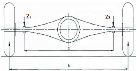
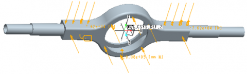
When the fully loaded vehicle travels through uneven pavement, the wheels are subjected to the maximum vertical force. Without considering lateral and tangent forces, the stress situation of the drive axle housing is illustrated in Figure 3.
Figure 3. Sketch map of maximum vertical force on drive axle housing
In this case, axle housing is simplified as a simply-supported beam; the axle housing is supported on the hub by the half-axle sleeve bearing. The half-axle sleeve is supported on the centerline of the wheels. Suppose the load on the two steel plate spring seats equals 2.5 times the full-load axial load. Then, the maximum vertical force can be described by:
$Z_{L}=G \cdot a /(a+b)=63700 \mathrm{~N}$ (1)
$Z_{R}=G \cdot b /(a+b)=63700 \mathrm{~N}$ (2)
where, G=127,400N is the full-load axial load of drive axle housing; a=591mm is the distance from the midpoint of the left steel plate spring seat to the midpoint of axle housing; b=591mm is the distance from the midpoint of the left steel plate spring seat to the midpoint of axle housing; ZL=63,700N is the load on the left steel plate spring seat; ZR=63,700N is the load on the right steel plate spring seat.
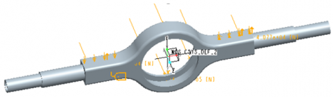
4.2 Maximum traction
Figure 4. Sketch map of maximum traction on drive axle housing
In this working condition, the fully loaded vehicle moves straightly with the maximum traction. Without considering lateral force, the stress situation of the drive axle housing is illustrated in Figure 4. In this case, the left and right driving wheels suffer a reaction force to the maximum tangent force from the ground (i.e., the traction), in addition to the vertical reaction force. Then, the maximum vertical load can be described by:
$P_{\max }=\frac{T_{e \max }\quad i_{g I}\quad i_{0}\quad \eta_{T}}{r_{r}}=152400 \mathrm{~N}$ (3)
where, Temax=1,100N·m is the maximum torque of the engine; igI=8.08 is the transmission ratio of gear I; i0=4.8 is the main deceleration ratio of the drive axle; ηT=0.8 is the transmission efficiency; rr=0.5464m is the rolling radius of driving wheels.
Since the drive axle works on several types of engines, and the reaction force torque created by the driving torque transmitted by the drive axle depends on the maximum friction of the ground, the torque provided by the maximum friction of the ground can be calculated by:
$T=G_{1} k_{1} \varphi r_{r} \approx m_{1} g k_{1} \varphi r_{r} \approx 62650.224 \mathrm{~N} \cdot m$ (4)
where, rr=0.5464m is the rolling radius of driving wheels; φ=0.85 is the attachment coefficient between driving wheels and pavement; k1=1.2 is the rated coefficient.
4.3 Maximum braking force
Figure 5. Sketch map of maximum braking force on drive axle housing
In this working condition, the fully loaded vehicle brakes under emergency. Without considering lateral force, the stress situation of the drive axle housing is illustrated in Figure 5. In this case, the left and right driving wheels suffer a brake force from the ground, in addition to the vertical reaction force. Then, the maximum vertical load can be described by:
$F=\frac{G m^{\prime} \varphi}{2}=40768 \mathrm{~N}$ (5)
where, G=127,400N is the full-load axial load of drive axle housing; m’=0.75 is the mass transfer coefficient during braking; φ=0.85 is the attachment coefficient between driving wheels and pavement. The outside of the two steel plate spring seats also suffer the torque T induced by the braking force:
$T=G_{2} k_{2} \varphi r_{r} \approx m_{2} g k_{2} \varphi r_{r} \approx 41766.8 \mathrm{~N} \cdot m$ (6)
where, rr=0.5464m is the rolling radius of driving wheels; φ=0.85 is the attachment coefficient between driving wheels and pavement.
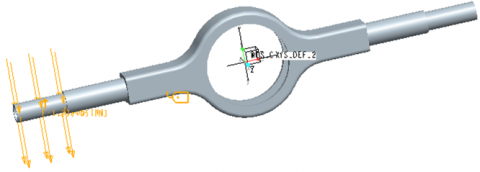
4.4 Maximum lateral force
When the fully loaded vehicle turns at a high speed, a very large centrifugal force will appear and act on the centroid, i.e., the lateral force. When the force reaches the maximum lateral reaction force from the ground, i.e., the lateral attachment force, the vehicle will enter the critical state of sideslip. Once the lateral force exceeds the lateral attachment force, the vehicle will sideslip. Under this critical state, the drive wheel in the sideslip direction carries all the load of drive axle. Then, the lateral force on the drive axle can be expressed as:
$P=G \times \varphi_{1}$ (7)
where, G=127,400N is the full-load axial load of drive axle housing; φ1=1.00 is the lateral attachment coefficient between tires and the ground.
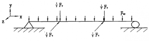
5.1 Load and constraint processing
The load on the axle housing was simplified to the form of a simply-supported beam. On the one end, the degrees of freedom were constrained in the X, Y, and Z directions; on the other end, the degrees of freedom were constrained in the Y and Z directions (Figure 6).
Figure 6. Forces and constraints on axle housing
Each load condition was directly applied to the nodes by computing the mean stress on each node, in the form of concentration force. Tables 1 and 2 show the load conditions and constraints of axle housing under different working conditions.
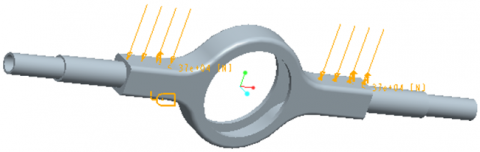
After defining materials, the loads applied to axle housing under the working conditions of maximum vertical force, maximum traction, maximum braking force, and maximum lateral force are shown in Figures 7-10, respectively. The vertical force applied on spring seats amounted to 63,700N.
Figure 7. Loading condition under maximum vertical force
Figure 8. Loading condition under maximum traction
Figure 9. Loading condition under maximum braking force
Table 1. Load conditions
|
Working conditions |
Load conditions |
|
Maximum vertical force |
Apply vertical force evenly to the nodes on spring seats. |
|
Maximum traction |
Apply vertical force on the nodes of wheel spacing along the moving direction. |
|
Maximum braking force |
Apply vertical force on the nodes of wheel spacing, and maximum braking force opposite to the moving direction; apply braking torque on the nodes at the bolt holes of the two side flanges. |
|
Maximum lateral force |
Apply vertical force on the nodes of wheel spacing, and maximum lateral force in the horizontal direction. |
Table 2. Constraints
|
Working conditions |
Constraints |
|
Maximum vertical force |
Constrain the translation in X and Z directions and rotation about Y direction at the nodes of wheel spacing; constrain the translation in Z direction of central node of axle housing to eliminate the rigid body displacement of axle housing. |
|
Maximum traction |
At one steel plate spring seat, constrain the translation in X, Y, and Z directions, and rotation about Y direction; at the other steel plate spring seat, constrain the translation in X and Z directions, and rotation about Y direction. |
|
Maximum braking force |
At one steel plate spring seat, constrain the translation in X, and Y, directions, and rotation about Y direction; at the other steel plate spring seat, constrain the translation in X direction, and rotation about Y direction; constrain the degree of freedom in Z direction at bolt nodes of left and right flanges. |
|
Maximum lateral force |
At one steel plate spring seat, constrain the translation in X, Y, and Z directions, and rotation about Y direction; at the other steel plate spring seat, constrain the translation in X and Z directions, and rotation about Y direction. |
Figure 10. Loading condition under maximum lateral force
5.2 Stress analysis
5.2.1 Maximum vertical force
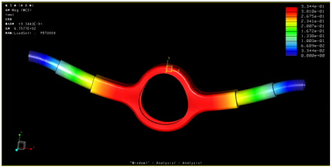
Figure 11 shows the vertical deformation of axle housing under maximum vertical force. The peak displacement occurred at the center of the axle housing, and gradually decreased to the two sides. The vertical (Y direction) displacement maximized at 0.334mm at the middle of the structure.
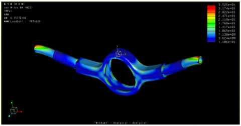
Figure 12 shows the stress distribution under maximum vertical force. The constraints on the two ends of wheels cause the stress near the hub bearing to deviate from reality, but do not affect the stress distribution in other parts of axle housing. It can be seen that relatively high stress appeared on the two end pipes of axle housing, peaking at 35.25MPa.
Figure 11. Vertical deformation under maximum vertical force
Figure 12. Stress distribution under maximum vertical force
5.2.2 Maximum traction
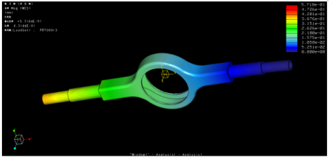
When the vehicle drove under the maximum traction, the longitudinal (Z-axis) displacement of the axle housing (Figure 13) was larger than that in the other two directions. The peak longitudinal displacement occurred in the upper part of the central area of axle housing.
Figure 13. Longitudinal deformation under maximum traction
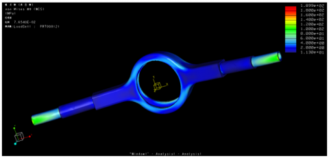
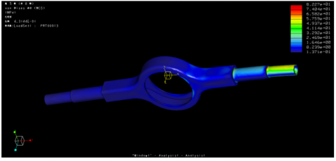
Figure 14 describes the stress distribution under maximum traction. The stress was relatively high at the two ends of axle housing, roughly 200.0MPa.
Figure 14. Stress distribution under maximum traction
5.2.3 Maximum braking force
When the vehicle drove under the maximum braking force, the longitudinal (Z-axis) displacement of the axle housing (Figure 15) was larger than that in the other two directions. The peak longitudinal displacement of 0.525mm occurred in the upper part of the central area of axle housing.
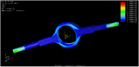
Figure 16 describes the stress distribution under maximum braking force. The stress was relatively high at the two ends of axle housing, roughly 189.9MPa.
Figure 15. Longitudinal deformation under maximum braking force
Figure 16. Stress distribution under maximum braking force
5.2.4 Maximum lateral force
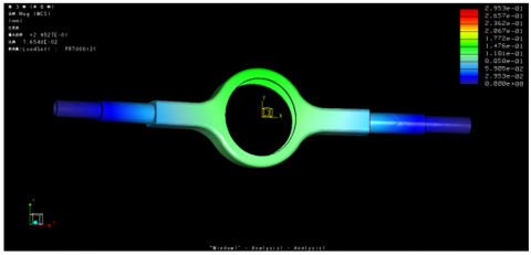
Figure 17 displays the deformation of axle housing under maximum lateral force. When the vehicle was under maximum lateral force, one end of axle housing did not deform, and the other end only deformed slightly. The largest deformation (0.572mm) took place at the end that was not subjected to any force.
Figure 17. Deformation under maximum lateral force
Figure 18 presents the stress distribution inside the axle housing. When the vehicle suffered the maximum lateral force, the high stress area concentrated near the inner bearing of sideslip end hub. The peak stress of 82.27MPa was located at the inside of the inner bearing.
Figure 18. Stress distribution under maximum lateral force
5.2.5 Performance evaluation
From the finite-element analysis and calculation results of axle housing under the four working conditions, the following conditions were drawn:
The evaluation metric for vertical bending test on drive axle housing is that the maximum deformation should not surpass 1.5mm per meter of wheel spacing, when the vehicle is fully loaded. The wheel spacing of the drive axle housing is 1.830m. From the above images of simulation results, the maximum deformation under each typical working condition is summarized in Table 3.
As shown in Table 3, the deformation of drive axle housing peaked at 0.312mm per meter of wheel spacing under the maximum lateral force, which is far smaller than the metric of 1.5mm. The actual peak deformation is even smaller, because the maximum deformation is actually that of half-axal sleeve. Hence, the drive axle housing can meet design requirements in all four typical conditions. Under maximum traction and maximum braking force, the torque on drive axle housing can be considered as the static torque of drive axle housing; the most deformed part is the half-axal sleeve. Next, under all four typical working conditions, the maximum equivalent stress of drive axle housing was always smaller than the allowable stress (570MPa) of axle housing materials, suggesting that the drive axle housing meets the requirements on strength design.
Table 3. Maximum deformation under each typical working condition
|
Working conditions |
Maximum vertical force |
Maximum traction |
Maximum braking force |
Maximum lateral force |
|
Maximum deformation (mm) |
0.334 |
0.295 |
0.525 |
0.572 |
|
Deformation per meter of wheel spacing (mm) |
0.183 |
0.161 |
0.287 |
0.312 |
This paper introduces the development of high-strength steels for hot stamped, cold stamped, and mechanically expanded axle housing. Taking the drive axle housing of Steyr heavy trucks for example, the authors provided the detailed design of drive axle housing. Based on static analysis and finite-element analysis, a 3D model was established for drive axle housing on Pro/ENGINEER. Then, the stress and deformation of drive axle housing were analyzed under four typical working conditions, using Pro/Mechanica. The results show that the axle housing meets the strength requirements, and leaves a room for improvement. The research provides theoretical basis for lightweight design of drive axle housing.
[1] Heidsieck, K., Wallgren, K. (2016). Rear axle system with multifunctional variability. ATZ Worldwide, 118(7): 56-59. https://doi.org/10.1007/S38311-016-0076-7
[2] Firat, M. (2011). A computer simulation of four-point bending fatigue of a rear axle assembly. Engineering Failure Analysis, 18(8): 2137-2148.
[3] Kepka, M., Kepka Jr, M. (2017). Calculations of fatigue life of a welded joint in the construction of the trolleybus rear axle. Procedia Structural Integrity, 5: 1409-1416. https://doi.org/10.1016/j.prostr.2017.07.205
[4] Kepka, M., Kepka Jr, M. (2018). Deterministic and probabilistic fatigue life calculations of a damaged welded joint in the construction of the trolleybus rear axle. Engineering Failure Analysis, 93: 257-267.https://doi.org/10.1016/j.engfailanal.2018.07.015
[5] Kepka, M., Kepka Jr, M. (2018). Parametric calculations of fatigue life of critical part of trolleybus rear axle. Procedia Engineering, 213: 227-238. https://doi.org/10.1016/j.proeng.2018.02.024
[6] Kepka, M., Kepka Jr, M. (2020). Accelerated fatigue testing on special tracks as new part of methodology for bus/trolleybus development. Engineering Failure Analysis, 118: 104786.https://doi.org/10.1016/ j.engfailanal.2020.104786
[7] Xu, C.G., Li, P., Guo, Y.Q., Zeng, J., Jin, H. (2017). Analysis and experimental study on compound mechanical bulging process for medium-sized vehicle drive axle housing. Procedia Engineering, 207: 1737-1742. https://doi.org/10.1016/j.proeng.2017.10.931
[8] Cui, Y.Y. (2018). Design Optimization and Finite Element Analysis of Axle Housing for Steering Drive Bridge. Shandong University.
[9] Li, L.Y. (2018). Fatigue Life Analysis of Loader Drive Axle Housing with Finite Element Method. Jilin University.
[10] Pirmohammad, S., Esmaeili-Marzdashti, S. (2019). Multi-objective crashworthiness optimization of square and octagonal bitubal structures including different hole shapes. Thin-Walled Structures, 139: 126-138. https://doi.org/10.1016/j.tws.2019.03.004
[11] Fu, W., Liu, L., Jin, S., Wang, D., Long, X. (2016). Dynamic simulation analysis of pothole event based on vRLDA. SAE Technical Paper. https://doi.org/10.4271/2016-01-0451
[12] Navid, A., Khalilarya, S., Abbasi, M. (2018). Diesel engine optimization with multi-objective performance characteristics by non-evolutionary Nelder-Mead algorithm: Sobol sequence and Latin hypercube sampling methods comparison in DoE process. Fuel, 228: 349-367. https://doi.org/10.1016/j.fuel.2018.04.142
[13] More, R., Vachhani, D., Raval, C. (2015). Durability prediction of rear engine bus using virtual proving ground road loads. SAE Technical Paper. https://doi.org/10.4271/2015-26-0237
[14] Brandes, S., Hilf, K.D., Möller, R., Melz, T. (2016). Durability simulation with chassis control systems: model depth for a handling maneuver. SAE International Journal of Passenger Cars-Mechanical Systems, 9: 1289-1296. https://doi.org/10.4271/2016-01-9111
[15] Sui, J.Y. (2017). Study on the design and manufacture of bearing capacity of impact welding axle housing. Shandong University.
[16] Sun, S., Cai, M., Ding, H., Huang, H., Pan, H. (2021). Deformation mechanisms of a novel Mn-based 1 GPa TRIP/TWIP assisted lightweight steel with 63% ductility. Materials Science and Engineering: A, 802: 140658. https://doi.org/10.1016/J.MSEA.2020.140658
[17] Caro, L.P., Odenberger, E.L., Schill, M., Niklasson, F., Åkerfeldt, P., Oldenburg, M. (2021). Springback prediction and validation in hot forming of a double-curved component in alloy 718. International Journal of Material Forming, 1-19. https://doi.org/10.1007/S12289-021-01615-X
[18] Gerstein, G., Kahra, C., Golovko, O., Schäfke, F., Klose, C., Herbst, S., Nürnberger, F., Maier, H.J. (2021). Hot forming of shape memory alloys in steel shells: formability, interface, bonding quality. Production Engineering, 15(2): 271-283. https://doi.org/10.1007/S11740-021-01024-8
[19] Dai, Y., Ji, J., Luo, L. (2018). Simulation study on hot stamping forming of the drive axle housing of heavy truck. IOP Conference Series: Materials Science and Engineering, 301(1): 012047. http://doi.org/10.1088/1757-899X/301/1/012047
[20] Zhang, W., Ding, C., Wang, H., Meng, W., Xu, Z., Wang, J. (2021). The forming profile model for cold metal transfer and plasma wire-arc deposition of nickel-based alloy. Journal of Materials Engineering and Performance, 1-10. https://doi.org/10.1007/S11665-021-05485-X
[21] Kumar, G.S., Kumaraswamidhas, L.A. (2021). Design optimization focused on failures during developmental testing of the fabricated rear-axle housing. Engineering Failure Analysis, 120: 104999. https://doi.org/10.1016/j.engfailanal.2020.104999