Chiranjit Bhowmik* | Prasun Chakraborti
OPEN ACCESS
Using of composite materials as lattice transmission tower structural material is increasing over conventional zinc galvanized steel materials because of some special features. Special attention should be paid regarding strength and stability of the transmission tower structure which are made with composite materials. In this present study, an effort has been made to analyze the strength and stability of transmission tower made with composite material, Carbon Fiber Epoxy (CFE). The transmission tower is modeled in STAAD considering CFE as structural material to analyze it in terms of strength and stability with different loading conditions in real life application. The maximum tensile stress is found at the transmission tower members near to the base of the structure with the amount of 210MPa. The breaking stress of CFE material is 1200MPa which is much more than the tensile stress occurs at the transmission tower at different loading conditions. The innovative design approach incorporating stability analysis found to be most competent for stating the stability and strength of tower and further clarify the safety approach of design.
transmission line tower, strength, stability, CFE, STAAD
Electricity transmission network is an important infrastructure for civilization, which assumes a critical part in improvement of economy and society for any country. Electric transmission network is necessary to provide electricity to every house and commercial sectors. This network is again needed due to uneven disposition of natural resources. Extra-High-Voltage (EHV) tower are the supporting piece of the transmission network to guide the overhead power lines which are constructed by steel L section members. Wellbeing and reliability of transmission towers precisely impact the regular function of the entire transmission network including the development of the society [1].
Most vibration studies on transmission line systems are conducted on transmission towers under wind loads [2-3]. Transmission towers are severely excited due to the effect of wind as well as earthquake. The dynamic excitations of transmission towers are nonlinear vibration in nature because of their complex geometrical configuration and other boundary condition. Because of the transmission line vibration, transmission towers are subjected to the dynamic loading which is frequency dependent, leads to the transmission tower’s failure, many have been reported in the literature [4-7]. To study the dynamical and modal properties of transmission tower structures for monitoring and protecting the designed structure many research have been carried out over the many decades in the aspect of analytical and experimental ground. It is challenging to simulate coupled conductor/tower behaviors using full solid FE models: Cable vibration alone is difficult to model using finite element method [8-9]. Hence, simplified models, which take into account the coupling characteristics, have been developed for transmission tower-line systems [10-11]. Studies of the free vibration of transmission pole structures are limited: modal tests on several concrete pole structures under free-free boundary conditions and developed distributed mass models using ANSYS [12-14]. Identified vibration modes of pre-stressed concrete poles using both modal testing and FE simulation is one of the ways for dynamic analysis through natural frequency of composite poles [15-16].
Nowadays, using composite materials as a transmission tower structural material is rapidly increased last few decades over conventional zinc galvanized steel materials because of some special features over conventional steel materials. Special advantages are durability, light in weight, less corrosiveness, less maintenance and so on. Special attention should be paid regarding strength and stability of the transmission tower structure which are made with composite materials. In this present study, an effort has been made to analyze the strength and stability of transmission tower made with composite material, Carbon Fiber Epoxy (CFE). The transmission tower is modeled in STAAD considering CFE as structural material to analyze it in terms of strength and stability with different loading conditions in real life application. The maximum tensile stress is found at the transmission tower members near to the base of the structure with the amount of 210MPa. The breaking stress of CFE material is 1200MPa which is much more than the tensile stress occurs at the transmission tower at different loading conditions. The innovative design approach incorporating stability analysis found to be most competent for stating the stability of tower and further clarify the safety approach of design.
The remainder of this paper is organized as follows: Section 2 introduces different forces/loads associated with transmission tower, Section 3 describes strength and stability analysis of transmission tower in staad pro and section 4 concludes the paper.
To determine the height of tower it is necessary to calculate the sag of the wires at maximum temperature of the surrounding. Sag of the wire can be calculated from the tension in the wire at corresponding temperature. Wire tension can be calculated by Eq. 1.
$T^2 [(T-T_1 )+∝(t_2-t_1 )EA+(EAL^2 W_1^2)/(24T_1^2 )]=(EAL^2 W_2^2)/24$ (1)
Wind load on structural body, wire, and insulator can be calculated by the taking consideration of windward force on the face and wind intensity, which is converted into point loads. Table 1 gives the transverse wind load on tower structure. Due to angle deviation, transverse load may be calculated by the following formulas,
Force due to deviation
= 2×T×sinɵ, for normal condition (NC).
=1×T×sinɵ, for broken wire condition (BWC).
Unbalanced load is acting on tower structure because of conductor breaking. Table 1 gives the longitudinal load on conductors and earth wire at NC and BWC respectfully. The unbalanced pull can be calculated as follows
Unbalanced pull
= 0.5×T×cosɵ, for anyone conductor broken.
= 1×T×cosɵ, for earth wire broken.
Total vertical load comprises of dead weight of structure, weight of all accessories including insulators, and weight of line man for repairing. Table 1 states the calculated vertical load of the tower at NC as well as BWC [17].
Table 1. Calculated transverse, longitudinal and vertical load
|
Loads/forces |
Conductor support |
Earth wire support |
||
|
NC |
BWC |
NC |
BWC |
|
|
Transverse Load (kg) |
457 |
281 |
191 |
110 |
|
Longitudinal Load (kg) |
1403 |
1507 |
1416 |
1465 |
|
Vertical Load (kg) |
707 |
512 |
370 |
284 |
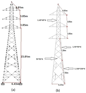
In this present study, an ordinary 132 KV lattice tower is chosen as an objective structure shown in Figure 1. In particular, slanted members utilize larger cross sectional members and are ceaseless at the associating joints since they are major leading members, while diagonal braces, cross arms, and other beams smaller angled members. Also, the FE demonstration depends on the accompanying some fundamental suppositions: (i) The individuals are straight, and cross-sections stay unaltered in length of the individuals; (ii) The angled member material is isotropic in nature and versatile; (iii) The strain of the individuals is unaltered among all purposes of a part; (iv) The tower structure is of large displacement and little strain, and twisting instigated changes in area region are slighted; (v) All the members are two-forced members, and the members are associated by hinge joints.
Table 2. Proposed design parameters for transmission tower
|
Design parameters |
Proposed values |
|
1.wind pressure as per medium zone |
|
|
a) On conductor |
0.0045 kg/cm² |
|
b) On earth wire |
0.0045 kg/cm² |
|
c) On tower body |
0.0203 kg/cm² & 0.0195 kg/cm² |
|
2. Factor of safety of conductor and earth wire |
|
|
i) At full wind |
2 |
|
ii) 2/3rd the wind |
2 |
|
iii) Still air |
4 |
|
3.Span |
|
|
a) Normal span |
335 |
|
b) Wind span |
|
|
i) Normal condition |
335 |
|
ii) BWC |
201 |
|
c) Weight span |
|
|
i) Max. and min. for NC suspension tower |
500 & 200 |
|
ii) Max. and min. for BWC suspension tower |
300&100 |
|
4. Broken condition |
any one conductor or earth wire |
|
5. Limiting values of L/r ratio |
|
|
a) Leg members & lower members of cross arms |
120 |
|
b) Other member carrying computed stress |
200 |
|
c) Redundant members |
250 |
|
d) Tensile member |
375 |
|
6. Factor of safety of tower |
2 for NC, 1.5 for BWC |
The measurements of the objective lattice tower are shown in Figure 1. The objective tower structure is around 36 meters (m) in height with base width of 6 meters (m). The slanted members are 100*100*8 cross sectional measure whereas the secondary cross arms (diagonal braces, cross arms etc.) are 75*75*6, 50*50*6 cross sectional measure. The objective structure is comprised of CFE angled members connected eccentrically either by bolt or welled; Table 3 represents the suitable composite materials for transmission tower available in market. Table 2 shows the proposed design parameters for the lattice transmission tower.
Figure 1. The configuration of existing 132 kv transmission tower with necessary dimensions
Table 3. Suitable composite materials for transmission tower available in market
|
Composite materials |
Young modulus (Gpa) |
Breaking stress (Mpa) |
|
Glass fiber polyamide 6 (thermoplastic) |
29 |
450 |
|
Carbon fiber epoxy (thermoset) |
109 |
1200 |
|
Carbon fiber rigid polyurethane (thermoplastic) |
28 |
427 |
|
Long carbon fiber, nylon66 (thermoplastic) |
36 |
507 |
Table 4. Proposed wire parameters
|
Parameters |
Conductor wire |
Ground wire |
|
Name of the conductor |
"ACSR PANTHER" |
GSW 7/3.15 |
|
Area (cm²) |
2.615 |
0.5455 |
|
Diameter (cm) |
2.1 |
0.945 |
|
Weight of the conductor (kg/cm) |
0.00974 |
0.00428 |
|
Ultimate tensile strength (kg) |
9144 |
5710 |
|
Modulus of elasticity (kg/cm²) |
815400 |
1933000 |
|
Maximum working span (cm) |
33500 |
33500 |
|
Co-efficient of linear expansion (/°C) |
1.78E-05 |
1.15E-05 |
|
Sag (cm) |
NA |
443.8 |
The lattice tower in its working conditions, experiences the impact of the power caring wires it conveys. The steel-cored aluminum strand wire "ACSR PANTHER 30/3.00+7/3.00” has picked as the appropriated power cables, and the wire specification are appeared in Table 4. Since the sectional measurement of the wires is long not as much as the traverse distance between structures, the flexural rigidity nature of the wires has disregarded.
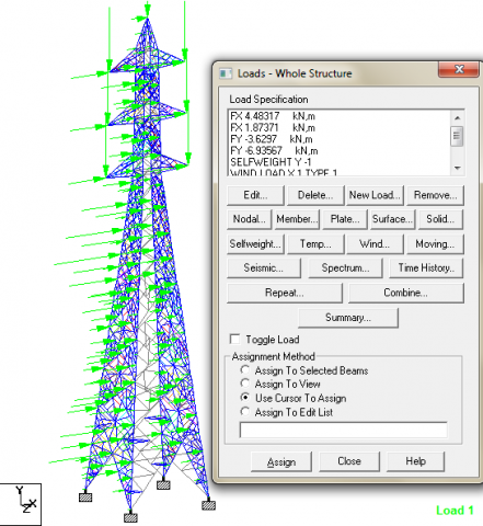
Transmission line tower is facing various types of forces in the application ground. Different kind of forces are consists of three main groups; Transverse Load, Longitudinal Loads and Vertical Loads. The specific formulas for calculating the different loads in correct and accurate manner are already discussed in section 2. Table 1 shows the calculated transverse, longitudinal and vertical load as per IS Transmission Tower Code Manual. The manually calculated different loads are applied to the objective tower as per instruction given in the Code Manual. Figure 2 shows the different loads are acting to the objective tower structure.
Figure 2. Different loads are acting on the transmission tower
The stability of the transmission tower can be analyzed by considering the strength of the individual member. The transmission tower may fail it’s stability due to the breaking of one member in the structure. Hence it is necessary to analyze each and every member of the structure accurately and precisely. It has been observed that the maximum tensile stress occurs at the transmission tower members near to the base of the structure with the amount of 210 MPa, Figure 3 shows the maximum a) Axial Force (b) Torsion (c) Stress Level (d) Displacement of the transmission tower members. The breaking stress of CFE material is 1200 MPa which is more than the tensile stress occurs at the transmission tower at different loading conditions in actual field application, table 3 shows the breaking stress of different composite materials. As the tensile stress occurs at the transmission tower members lower than the breaking stress of the used composite material, hence the structure is safe in actual field as per as the structural stability is concern. The lower part members have to provide higher sectional members to withstand more load and less deformed than that of the top part members so that the tower structure is to be found safe in any environmental situation. As per as the snapping of power cables is concern, there is a generation of torque on the transmission tower middle part, Figure 3 (b) shows.
Figure 3. Results obtain from STAAD pro (a) axial force (b) torsion (c) stress (d) displacement
From the above study, the following can be concluded
i. Wind intensity and resulting snapping of tower line can generate huge torque responsible for tower failure in the majority of the cases.
ii. The lower part members have to provide higher sectional members to withstand more load and less deformed than that of the top part members so that the tower structure is to be found safe in any environmental situation.
iii. The maximum tensile stress occurs at the transmission tower members near to the base of the structure with the amount of 210 MPa. The breaking stress of CFE material is 1200 MPa. As the tensile stress occurs at the transmission tower members lower than the breaking stress of the used composite material, hence the structure is safe in actual field as per as the structural stability is concern.
This study just manages one ordinary tower; the investigation technique displayed in this study can be promptly reached out to different kinds of lattice transmission tower. The accuracy and legitimacy of the numerical reenactment ought to be further endorsed and changed by testing to apply in real application.
We want to thank Ministry of Human Resource Development (MHRD), INDIA for the funding of this research. We also want to thank to the Director and HOD Mechanical, NIT Agartala, INDIA for their continuous support and motivation.
T tension of conductor at maximum atmospheric temperature,
T1 permissible tension in wire,
A effective cross-sectional area of wire
E modulus of elasticity of wire material,
(t2 - t1) variation of temperature,
α coefficient of linear expansion,
L wind span
W1 sum of the weight of wire and the wind force on wire
W2 self-weight of wire