María Claudia Abeledo*![]() | Daniel Alberto Priano
| Daniel Alberto Priano![]() | Javier Guevara
| Javier Guevara![]() | Fabio Sergio Bruschetti
| Fabio Sergio Bruschetti![]()
© 2023 IIETA. This article is published by IIETA and is licensed under the CC BY 4.0 license (http://creativecommons.org/licenses/by/4.0/).
OPEN ACCESS
The following article presents a comparison of flow forwarding between traditional and software-defined networks (SDN), focusing on the impact of routing protocols and policies. The present work evaluates the efficiency of SDN routing (bandwidth and packet loss) against the performance obtained in traditional networks and estimates the performance variation when using ad-hoc software implementations such as OpenVSwitch [1].
SDN, routing policies and protocols, network performance, OpenVSwitch, QoS, flow prioritization
Traditional routing protocols such as OSPF [2], BGP [3], RIP [4] and EIGRP [5] have been extensive and complete developments resulting in complex and rigid systems that are difficult to adapt to the current requirements of user services through the Internet. This rigidity reduces the possibility of use these protocols in networks with high volume of complex data types to be transmitted. The appearance of SDN [6] has introduced new concepts to solve this kind of problems.
Due to the increase in unforeseen failures in communication networks, it has become crucial to predict and know the approximate maximum time it takes the network to avoid or minimize packet and data loss.
Routers, with their traditional network routing protocols, require considerable convergence time decreasing bandwidth and increasing packet loss. This convergence time and its impact are present in SDN too so they will be critically important to benchmark networks performance's.
The chosen scenario is generally used to present routing protocols problems over traditional networks and to identify solutions defined through Traffic Engineering (TE) and Quality of Service (QoS). Those solutions will include routing protocols, QoS policies and load balancing mechanisms. The topology of the scenario is shown below in Figure 1.
The network traffic flows from VM1 and VM2 (Virtual Machine 1 and 2) to the through PE1 (Border Router) to enter to AREA 0 (shaded in yellow) according to the queuing system. A brief description of the types of routing queues and, particularly the one chosen for the development of this work, is detailed as follows.
Figure 1. Analysis scenario
2.1 Queue types
The queuing system will be defined with one or more flows that may or may not enter a congested network. Queuing mechanisms are determinant regarding the performance of data networks. The different existing queuing mechanisms will have different bandwidths, delays, jitters and packet losses depending on the network congestion. In case of QoS, the following methods are used:
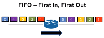
FIFO Queuing (First In First Out) [7]: There are no priorities or classification of types of traffic. The first packet to enter this queuing system is the first to leave, as shown in Figure 2.
Source: Cisco Systems
Figure 2. FIFO Queuing
WFQ (Weighted Fair Queuing): This queuing method generates a different queue with its priority for each flow type. When a queue is empty of packets, the system continues with the next priority queue as shown in Figure 3.
Source: Cisco Systems
Figure 3. WFQ mechanism
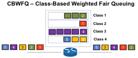
CBWFQ (Class Based Weighted Fair Queuing): Because WFQ has scaling limitations when the traffic per link increases, CBWFQ incorporates the use of a weighted Round Robin algorithm where it establishes different attention times for each queue depending on the guaranteed bandwidth for each of them, as shown in Figure 4.
Source: Cisco Systems
Figure 4. CBWFQ mechanism
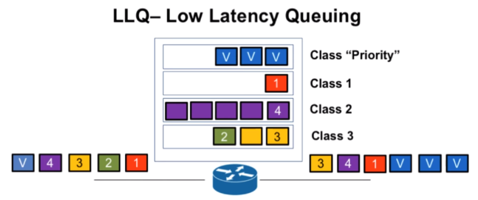
LLQ (Low Latency Queueing): It is an extension of the CBWFQ mechanism that adds an additional PQ queue with the highest priority over the others as shows in Figure 5. LLQ queuing (CBWFQ + PQ) is currently the most recommended method for VoIP, IP telephony and video conferencing.
Source: Cisco Systems
Figure 5. LLQ mechanism
This work uses the CBWFQ (Figure 4) and LLQ (Figure 5) queues. Our experiment will prioritize the UDP flow taking as a premise to obtain the minimum loss of packets. For this reason, the queue model considered was the one that allows assigning absolute priorities, the LLQ protocol.
Although UDP is used in applications that can be treated as Best Effort and as a transport for real-time applications, this work will not focus on these characteristics within the experimentation.
Two scenarios were designed where each of them will incorporate an improvement over the previous one. These two scenarios were considered for both traditional and SDN networks.
Traditional networks scenario: A single TCP stream will be sent to test the available bandwidth for network saturation. In the following test, a TCP flow and a UDP flow are sent along the path that the routing protocol has defined. Finally, both flows are sent again adding QoS policies.
SDN scenario: We will force the sending of a TCP flow through the longest route with the same objective as in the case of traditional networks. TCP and UDP streams are then sent in order to improve packet loss mitigation. The UDP stream will be sent by the shortest path.
4.1 Traditional networks scenario
4.1.1 Test without QoS, with Iperf3 [8], single stream over GNS3 [9], OSPF protocol
A first TCP stream is sent over port 5201 from VM1 to VM3. With this configuration we obtain that the capacity of the system is approximately 17 Mbps at the moment of starting the packet loss. This result will set the bandwidth limit as a parameter in the subsequent performance tests of this scenario. The OSPF protocol chose the path PE1–P4–P5–PE2 within “Area 0” as shown in Figure 6.
Figure 6. Route chosen by the OSPF protocol
Figure 7 shows the sending of the TCP flow generated in Iperf from VM1 to VM3 through port 5201 in VM1.
Figure 7. Iperf3 outcome
Results: Figure 8 shows the TCP flows sent. We can appreciate the maximum capacity of the system (Bandwidth).
Own source
Figure 8. Bandwidth performance test
4.1.2 Test without QoS, with Iperf3, double streams over GNS3, OSPF protocol
Two flows were sent, one from VM1 to VM3 and one from VM2 to VM3. UDP streams were sent through port 5060 and TCP through port 5201 respectively. According to the OSPF protocol, the chosen route is the same as in the previous case, PE1–P4–P5–PE2.
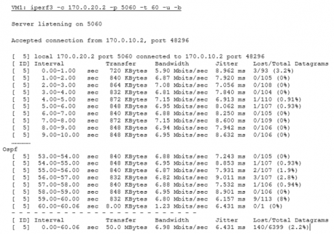
Figure 9 shows the output generated by Iperf3 of the UDP flow sent from VM1 to VM3.
Figure 9. Iperf3 output for UDP flow
Figure 10 shows the output generated by Iperf3 of the TCP flow sent from VM2 to VM3.
Figure 10. Iperf3 output for TCP flow
Results: In Figure 11 we can see the difference in the bandwidth used by each of the flows. The UDP flow tries to gain the maximum bandwidth allowed by the system, but the TCP flow limits its maximum reach.
Own source
Figure 11. Bandwidth used by UDP and TCP flows
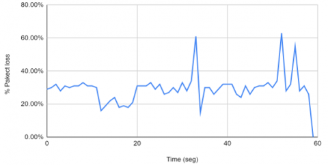
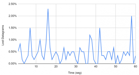
On the other hand, the percentage of packets lost for the UDP flow reaches peaks around 60% as shown in Figure 12.
Own source
Figure 12. Packet loss in UDP flows
4.1.3 Test with QoS, with Iperf3, double streams over GNS3, OSPF protocol
In the previous tests with UDP and TCP flows without QoS (experiment 4.1.1) considerable packet losses were observed, especially in the UDP flow. This configuration will try to correct these losses by applying QoS policies on the chosen queuing mechanism.
In this test, a preferential delivery service is configured for the applications that needed it, ensuring sufficient bandwidth, controlling latency and reducing data loss.
Two flows were sent, one from VM1 to VM3 and one from VM2 to VM3. UDP streams were sent through port 5060 and TCP through port 5201 respectively. According to the OSPF protocol. The chosen route is the same as in the previous case. Figure 13 shows the UDP flow from VM1 to VM3 generated under Iperf3.
Figure 13. Iperf3 output for UDP flow
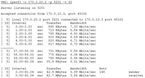
Figure 14 shows the output generated by Iperf3 of the TCP flow sent from VM2 to VM3.
Figure 14. Iperf3 output for TCP flow
Results: Compared to the previous test, it can be seen how both flows are stabilized and how the packet loss of UDP flows is significantly reduced. It can also be seen how UDP flows take full advantage of the 7 Mbps, leaving the remaining 10 Mbps to TCP flows (Figure 15). In GNS3, the total 17 Mbps of bandwidth has been defined as a parameter.
Own source
Figure 15. Bandwidth used by UDP and TCP flows with QoS
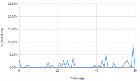
Figure 16 shows the considerable decrease of 40% in the average packet loss, which results in a final value of 4%.
Own source
Figure 16. Packet loss in the flow under UDP protocol with QoS
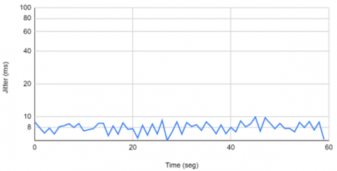
Figure 17 shows the result of jitter (delay variation) for the UDP flow.
Own source
Figure 17. Jitter of the UDP flow with the application of differentiated services
4.2 SDN networks scenario
4.2.1 Tests with Iperf3, single flow over Mininet [10], rule of minimum number of skips
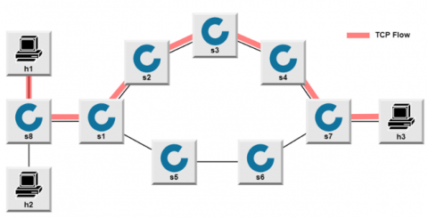
TCP streams are sent through port 5201 from h1 to h3 along the fixed path defined as s1–s2–s3–s4–s7. OSPF is not used. Figure 18 shows the scenario together with the limitation of interfaces.
Own source
Figure 18. SDN topology scenario for the TCP flow
To match the configuration of the tests developed in traditional networks, the maximum capacity of the system has been determined at 17 Mbps (Figure 19).
Figure 19. Limiting SDN Bandwidth on Mininet
As in the previous case, the bandwidth limit is decisive for the following performance tests. The following rules were established with priority 99:
• Decrement of TTL
• Modify ethernet address
• Exit by interface
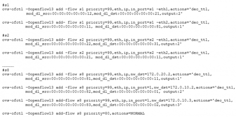
Figure 20 shows the configuration code for these rules in the Mininet simulator.
Figure 20. Mininet setup rules
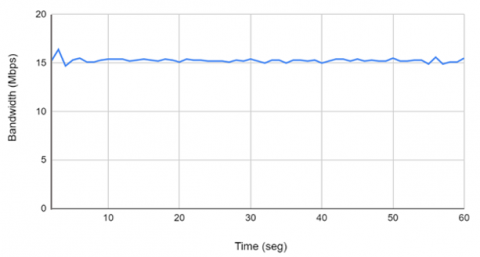
Results: It is observed that the bandwidth remains within the limits established by the parameters specified in the rules (Figure 21).
Own source
Figure 21. Bandwidth of the TCP flow
4.2.2 Tests with Iperf3, double stream over Mininet, traffic sent by the longest route
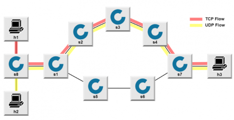
Two flows were sent, one TCP from h1 to h3 through port 5201 and another UDP from h2 to h3 through port 5202. The same route is used as in the previous case (Figure 18) as shown in Figure 22.
Own source
Figure 22. SDN topology scenario for the TCP and UDP flows through the same route
In Figure 23, we observe the bandwidths occupied by each of the flows.
Own source
Figure 23. Bandwidth of TCP and UDP flows
Results: The number of packets lost in UDP flow is considerably lower for the same flow observed in Figure 16 despite the fact that, in this case, the two flows were sent by the longest route (Figure 24).
Own source
Figure 24. Number of packets lost from the UDP flow
4.2.3 Tests with Iperf3, double stream over Mininet, rules: minimum number of skips for UDP flow and TCP flow sent by the longest route
The flows were divided as follows: the TCP flow is sent through the route s1–s2–s3–s4–s7 through port 5202 and the UDP flow through the route s1–s5–s6–s7 through the port 5201 (Figure 25).
Own source
Figure 25. SDN topology scenario for the TCP and UDP flows through different routes
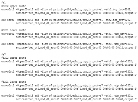
Set up of flows in Mininet (Figure 26):
• Flows with priority 100 on s1 and s7 to correspond to TCP/UDP ports
• TCP flow: 5202 port, s1–s2–s3–s4–s7 route
• UDP flow: 5201 port, s1–s5–s6–s7 route
Own source
Figure 26. Mininet setup of UDP and TCP flows
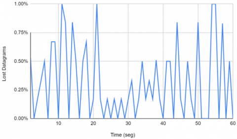
Results: Figure 27 shows that the bandwidth is not affected in either of the two flows. Also, in Figure 28, we appreciate UDP packet loss is significantly reduced to 1%.
Own source
Figure 27. Bandwidth of both streams
Own source
Figure 28. Lost packets for the UDP flow
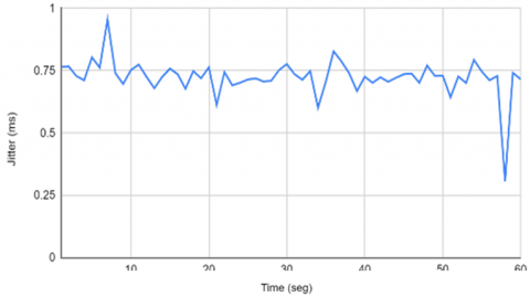
Figure 29 shows the result of the jitter (delay variation) for the UDP flow.
Own source
Figure 29. UDP flow jitter
4.3 Considerations for future experiments
In heterogeneous networks, both traditional and SDN, their developments have been much more complex. This brings many challenges to organize, manage and optimize network resources in a more effective way. One possible way to solve these problems is to incorporate more intelligence into networks as proposed by the Knowledge Plane approach (KP) [11] by applying Machine Learning (ML) [12] and cognitive techniques. However, the KP has not been prototyped or implemented at the time of writing this present work.
In traditional networks, each router or switch node can only see and act on a small portion of the network; If we need to control the entire network, it is very complex to learn from each node since they only have a small partial view of their environment. Future developments in SDN networks are expected to make it easier to learn the entire network as a whole [13].
To sustain end-to-end QoS it will be very important to dig into the dynamic behavior of networks through measured and monitored parameters. Among the parameters that determine whether the level of service offered is met, the most important are packet loss and jitter [14-16].
Following these considerations mentioned before, we can see that as we have simplified the schemes and configurations defined at the beginning, we have obtained conclusions that confirm the objectives established.
The conclusions obtained are detailed below:
|
BGP |
Border Gateway Protocol |
|
EIGRP |
Enhanced Interior Gateway Routing Protocol |
|
ex |
Lower hierarchy link x |
|
fx/y |
Top hierarchy link x/y |
|
GNS3 |
Graphical Network Simulator-3 software |
|
hx |
Host x |
|
IP |
Internet Protocol |
|
Iperf3 |
Network emulator software |
|
KP |
Knowledge Plane |
|
Mbps |
Megabits per second |
|
ML |
Machine Learning |
|
Mininet |
Network emulator software |
|
msec |
Miliseconds |
|
OSPF |
Open Shortest Path First |
|
Px |
Legacy Router x |
|
Pex |
Legacy Border Router x |
|
QoS |
Quality of Service |
|
RIP |
Routing Information Protocol |
|
sx |
SDN switch x |
|
SWx |
Legacy Switch x |
|
TCP |
Transmission Control Protocol |
|
TE |
Traffic Engineering |
|
TTL |
Time To Live |
|
UDP |
User Datagram Protocol |
|
VMx |
Virtual Machine x |
|
VoIP |
Voice over IP |
|
x.x.x.x/y |
IPV4 Address |
[1] OvS–OpenVswitch. (2022). https://www.openvswitch.org/.
[2] Open Shortest Path First Protocol. (2022). https://www.ietf.org/rfc/rfc2328.txt.
[3] A border gateway protocol 4 (BGP-4). (2006). https://tools.ietf.org/html/rfc4271.
[4] RIP Version 2. (1998). https://tools.ietf.org/html/rfc2453.
[5] Introduction to EIGRP. (2005). https://www.cisco.com/c/en/us/support/docs/ip/enhanced-interior-gateway-routing-protocol-eigrp/13669-1.html.
[6] ZDNet-What is SDN? How software-defined networking changed everything. (2018). https://www.zdnet.com/article/software-defined-networking-101-what-sdn-is-and-where-its-going.
[7] Queuing algorithm. (2022). https://ccnadesdecero.es/algoritmo-formacion-colas/.
[8] Iperf3. (2022). https://iperf.fr/iperf-download.php.
[9] GNS3-Complutense University of Madrid. (2022). https://www.ucm.es/pimcd2014-free-software/gns3.
[10] Introduction to Mininet. (2022). https://github.com/mininet/mininet/wiki/Introduction-to-Mininet.
[11] Clark, D.D., Partridge, C., Ramming, J.C., Wroclawski, J.T. (2003). A knowledge plane for the Internet. In Proceedings of the 2003 Conference on Applications, technologies, architectures, and protocols for computer communications, Karlsruhe, Germany, August 25-29, 2003, Association for Computing Machinery. pp. 3-10. https://doi.org/10.1145/863955.863957
[12] Mestres, A., Rodriguez-Natal, A., Carner, J., et al. (2017). Knowledge-defined networking. ACM SIGCOMM Computer Communication Review, 47(3): 2-10. https://doi.org/10.1145/3138808.3138810
[13] Wang, M., Cui, Y., Wang, X., Xiao, S., Jiang, J. (2017). Machine learning for networking: Workflow, advances and opportunities. IEEE Network, 32(2): 92-99. https://doi.org/10.1109/MNET.2017.1700200
[14] Braun, T., Diaz, M., Gabeiras, J.E., Staub, T. (2008). End-to-end quality of service over heterogeneous networks. Springer Science & Business Media.
[15] Egilmez, H.E., Dane, S.T., Bagci, K.T., Tekalp, A.M. (2012). OpenQoS: An OpenFlow controller design for multimedia delivery with end-to-end quality of service over software-defined networks. In Proceedings of the 2012 Asia Pacific Signal and Information Processing Association Annual Summit and Conference, Hollywood, CA, USA, December 3-6, 2012, IEEE, pp. 1-8.
[16] Duan, Q., Wang, C., Li, X. (2015). End-to-end service delivery with QoS guarantee in software defined networks. arXiv. https://doi.org /10.14738/tnc.62.4373