Yufei Peng | Hua Li* | Xiaoyan Li | Jikang Wang | Xinyu Zhang
© 2022 IIETA. This article is published by IIETA and is licensed under the CC BY 4.0 license (http://creativecommons.org/licenses/by/4.0/).
OPEN ACCESS
In the optical storage DC microgrid in island mode, in view of the large inrush current problem of the inverter controlled by the optical storage VSG when switching from off-grid to grid-connected operation mode, a pre-synchronization control strategy based on secondary frequency regulation and voltage regulation was proposed. This strategy can adjust the large frequency and voltage fluctuations caused by active and reactive load changes under the independent DC microgrid of the optical storage. At the same time, it can complete the effective tracking of the grid phase before connecting to the grid, and reduce the impulse current when the optical storage microgrid is isolated and connected to the grid. The real-time digital simulation platform (RTDS) is used to simulate and analyze the proposed control scheme, and the simulation results verify the feasibility of the proposed control strategy.
optical storage DC microgrid, VSG, pre-synchronization, secondary frequency modulation, phase synchronization
In recent years, with the continuous increase in the penetration rate of distributed power sources such as photovoltaics, the relative reduction in the proportion of traditional synchronous generators, the spinning reserve capacity and moment of inertia of the power system has brought severe challenges to the safe and stable operation of the power grid [1, 2]. The virtual synchronous generator simulates many characteristics of the synchronous generator, so that the distributed inverter power supply has the inertia and damping characteristics of the synchronous generator, which can not only slow down the transient process of the distributed inverter power supply, but also provide effective support for the system, Enhance the stability of the system, and open up a new way for distributed power sources to connect to the grid on a large scale [3, 4].
In view of the current research status of VSG off-grid pre-synchronization, Shi et al. [5] uses the combination of VSG and PQ control methods, and proposes a parallel switching method based on controller state following, which can track and avoid the phase and current commands of the two control modes in real time. The current impact during the switching process, but the structure is complicated and difficult to realize. The dual-mode control method does not affect each other, the switching is difficult and the switching speed is relatively slow, and it is easy to cause inrush current [6]. Wan et al. [7, 8] controls the output phase and voltage amplitude of VSG and the difference between the grid voltage phase and voltage amplitude through PI control output compensation to form a closed-loop control on the power loop to achieve pre-synchronization, but its control structure is more complex and needs There are many phase-locked loops. Wei et al. [9] adopts the virtual power method based on secondary frequency modulation and voltage regulation. It is assumed that there is a virtual impedance between the VSG terminal and the grid, and the virtual power is closed-loop controlled. When the virtual power is equal to zero, the pre-synchronization is completed, but the virtual impedance is not given. The specific calculation method is difficult to determine the virtual impedance value.
The above-mentioned research on VSG pre-synchronization mainly focuses on the AC side of the inverter, ignoring the actual operating conditions such as the dynamic characteristics of distributed energy such as photovoltaics and the coordination of DC side power, and the voltage source is equivalent to the DC side in an idealized research form. For this reason, the article designs a VSG control strategy in island mode including photovoltaic and energy storage. Under the background that the isolated island optical storage VSG needs to be connected to the grid, the traditional virtual synchronous generator has a differential frequency modulation and voltage regulation that cannot eliminate the frequency and voltage offset. Problem, a pre-synchronization control strategy based on secondary frequency modulation and voltage regulation is proposed and verified by RTDS simulation.
The overall control block diagram of the VSG strategy in the article is shown in Figure 1. The entire control strategy consists of the power frequency controller (P-f) and the excitation controller (Q-U) to generate the phase angle θ and amplitude E of the voltage Synchronous control strategy. θ and E generate voltage reference values through the reference voltage calculation link, and then through the voltage and current control link, the corresponding modulation signal is obtained through the PWM generator, and the virtual synchronous generator is controlled to output the voltage and current that meet the requirements. As shown in Figure 1, C1 is the DC side capacitor, L1 and L2 are filter inductors, C is the filter capacitor, I1abc and I2abc are the inverter side inductor current and the grid side output current respectively; egabc is the three-phase grid voltage.
Figure 1. Overall block diagram of VSG control strategy
Figure 2. Block diagram of optical storage VSG DC microgrid structure
Figure 3. Block diagram of energy management
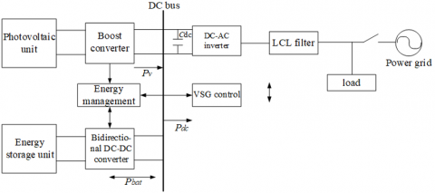
The structural block diagram of the optical storage VSG DC microgrid based on Figure 1 is shown in Figure 2. In the picture, the photovoltaic array and the energy storage unit are connected in parallel to the DC bus side through the Boost converter and the bidirectional DC-DC converter respectively; the downstream DC-AC inverter is connected to the AC load or the large power grid through the LCL filter circuit.
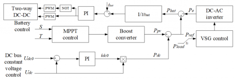
At the same time, in order to maintain the stability of the DC bus voltage, the energy storage unit is required to stabilize the power fluctuations caused by factors such as light and load changes. To this end, a dual closed-loop energy management control strategy between photovoltaic, energy storage and VSG inverters is established. As shown in Figure 3.
The switch S1 in the above figure determines the value of the VSG reference power Pref. In islanding mode, S1 tangents to the initial load Pload; under the pre-synchronization control strategy grid-connected mode, S1 tangential photovoltaic output power Ppv and Pdc is the difference side.
3.1 VSG active frequency modulation controller
According to the principle of synchronous generator frequency modulation, VSG adjusts the mechanical power according to the difference between the actual output angular frequency ωm and the inverter output angular frequency reference value ωref [10]. The input mechanical power Pm of VSG is:
$P_{\mathrm{m}}=P_{\mathrm{ref}}+K_{\omega}\left(\omega_{\mathrm{ref}}-\omega_{\mathrm{m}}\right)$ (1)
In the formula: Pref is the reference value of active power [11], Kω is the frequency modulation coefficient. Combine formula (1), establish the active frequency control link of VSG, as shown in Figure 4.
Figure 4. VSG active frequency modulation control principle diagram
3.2 VSG reactive voltage controller
The design of the VSG reactive power voltage controller is based on the principle of the synchronous generator excitation controller, the SG reactive power-voltage droop characteristic equation is:
$U_{\mathrm{ref}}=U_{\mathrm{n}}+K_{\mathrm{q}}\left(Q_{\mathrm{ref}}-Q\right)$ (2)
In the formula: Qref is the reference value of reactive power; Q is the actual reactive power; Un is the rated voltage amplitude of the system [12]; Uref is the reference voltage; Kq is the voltage regulation coefficient.
SG adjusts the difference between the reference voltage and the terminal voltage amplitude according to the excitation current.
$i_{\mathrm{f}}=\left(U_{\mathrm{ref}}-U\right)\left(K_{\mathrm{p}}+\frac{K_{\mathrm{i}}}{\mathrm{s}}\right)$ (3)
In the formula: U is the amplitude of the SG terminal voltage; Kp is the proportional coefficient; Ki is the integral coefficient.
The SG excitation current is directly equivalent to the voltage amplitude E of the VSG, and the equation (2) is substituted into the equation (3), and the control equation of the reactive voltage link of the VSG can be obtained as:
$E=\left[U_{\mathrm{ref}}-U+K_{\mathrm{q}}\left(Q_{\mathrm{ref}}-Q\right)\right]\left(K_{\mathrm{p}}+\frac{K_{\mathrm{i}}}{S}\right)$ (4)
According to formula (4), the reactive voltage control link of VSG is established, as shown in Figure 5 below.
Figure 5. VSG reactive voltage control principle diagram
4.1 VSG inverter parallel/off-grid mode switching
When switching from grid-connected to off-grid, the frequency and voltage output by the VSG inverter remain synchronized with the grid frequency and voltage. Therefore, due to the superiority of the VSG control strategy, there will be no serious transient adjustment process during the switch from grid-connected to off-grid, and the seamless switch from grid-connected to off-grid can be smoothly realized [13].
4.2 VSG inverter off/grid mode switching
When the VSG inverter is in off-grid operation mode, the VSG inverter adjusts the amplitude and frequency of the output voltage according to the load, so it will deviate from the amplitude and frequency of the grid voltage, and a large inrush current will be generated at the moment of grid connection. It is easy to cause grid connection failure [14]. Therefore, in order to ensure that the voltage amplitude, frequency, and phase are consistent in off-grid and grid-connected modes, pre-synchronization control is required.
4.3 Secondary frequency modulation and voltage regulation
Figure 6. Schematic diagram of secondary frequency modulation
To achieve pre-synchronization control before grid connection, a second frequency and voltage regulation is required. There is a droop characteristic between the active power and frequency of the VSG. As shown in Figure 6, when the frequency drops, the VSG can increase the output active power through a frequency modulation. In Figure 6, the operating point shifts from point a to point b; when the frequency rises on the contrary, at the same time, the first frequency modulation of VSG is also differentially adjusted. In order to achieve no-difference control, VSG realizes the secondary adjustment of frequency by simulating the link of the synchronous generator governor. At this time, the operating point is shifted from point b to point c in Figure 6.
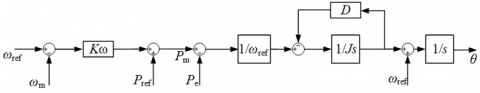
Drawing lessons from the above-mentioned power system frequency modulation principle, the integrator and damping torque are combined to form a PI controller in the VSG active frequency control link, so as to achieve the second frequency modulation of the frequency [15]. Therefore, the rotor motion equation is changed to:
$\mathrm{J} \frac{\mathrm{d} \Delta \omega}{\mathrm{dt}}=\frac{P_{\mathrm{m}}}{\omega_{\mathrm{ref}}}-\frac{P_{\mathrm{e}}}{\omega_{\mathrm{ref}}}-\left(D+\frac{K_{\mathrm{i}}}{S}\right)\left(\omega_{\mathrm{m}}-\omega_{\mathrm{g}}\right)$ (5)
where, Ki is the integral coefficient.
The simultaneous Laplace transform of (1) and (5) gives:
$\left(\omega_{\mathrm{m}}-\omega_{\mathrm{g}}\right)=\frac{\left(P_{\mathrm{ref}}-P_{\mathrm{e}}\right) S}{J \omega_{\mathrm{ref}} S+\left(D \omega_{\mathrm{ref}}+2 K_{\omega} / \pi\right) S+K_{\mathrm{i}} \omega_{\mathrm{ref}}}$ (6)
Then the initial value and final value when the load power changes are (assumed):
$\left\{\begin{array}{l}\lim _{t \rightarrow 0} \Delta \omega=\lim _{s \rightarrow \infty} \mathrm{s}(\Delta \omega / s)=0 \\ \lim _{t \rightarrow \infty} \Delta \omega=\lim _{s \rightarrow 0} \mathrm{~s}(\Delta \omega / s)=0\end{array}\right.$ (7)
It can be seen from the above that the introduction of the integral link can make the initial value and the final value of the frequency offset zero, which can achieve the non-difference control in the steady state.
When a voltage deviation occurs in the VSG, the difference between the VSG output voltage amplitude and the grid voltage amplitude is introduced in the reactive power-voltage control link, and the output is controlled by PI to make the VSG voltage amplitude consistent with the grid, achieving amplitude synchronization tracking the goal of.
4.4 Phase synchronization
The above-mentioned secondary frequency modulation and voltage regulation have made basic preparations for switching from island mode to grid-connected mode. In order to achieve grid-connected smoothly, it also needs to be consistent with the grid voltage phase. To this end, a phase difference detection link is added, and the grid-connected switch is automatically closed when the difference between the VSG output phase and the grid phase decreases to zero. The principle of the phase difference detection link: First, the grid voltage ug and the d axis are contracted to rotate at an angular velocity of ωg, and the VSG output voltage u1 rotates at an angular velocity of ω1. When u1 and ug coincide, that is, the q-axis component of u1 and the phase difference between u1 and ug Both are zero, and the voltage phases on both sides of the grid-connected point are synchronized at this time. The VSG grid-connected phase synchronization vector diagram and phase control diagram are shown in Figures 7 and 8.
For this reason, the overall control structure of pre-synchronization can be obtained as shown in Figure 9. In island mode, first switch S4 is kept at ωref, while switches S2, S3, and S5 are kept open; when the load changes, a second frequency regulation is performed, switches S2 and S3 are closed and S4 is cut to ωg, and adjust the frequency and voltage amplitude reach near the rated value; then the switch S5 is closed to synchronize the phase. After the pre-synchronization meets the grid-connected standard requirements, close the grid-connected switch PCC, and then open S2, S3, S5, and S4 tangential to ωref.
Figure 7. Phase synchronization vector diagram
Figure 8. Phase control diagram
Figure 9. The overall control block diagram of the VSG with pre-synchronization added
The real-time digital simulator (RTDS), as a real-time simulation tool of the power system, can truly and effectively reflect various problems that may occur when the system is running. In order to verify the effectiveness of the pre-synchronization control strategy based on secondary frequency modulation and voltage regulation, an optical storage VSG simulation model was built in RTDS. The corresponding simulation parameters are shown in Table 1.
Table 1. Optical storage VSG simulation parameters
|
Parameter name |
Value and Unit |
|
Grid line voltage |
380V |
|
DC voltage |
800V |
|
Rated frequency f |
50Hz |
|
Filter inductance L1 |
5mH |
|
Filter capacitor C |
500μf |
|
Moment of inertia J |
0.1kg·m/s2 |
|
Damping coefficient D |
6N·s/m |
|
Frequency modulation coefficient Kω |
100000 |
|
Pressure regulation coefficient Kq |
0.001 |
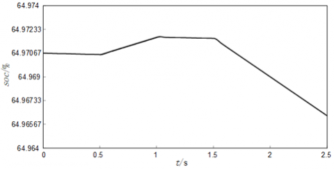
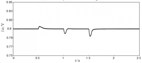
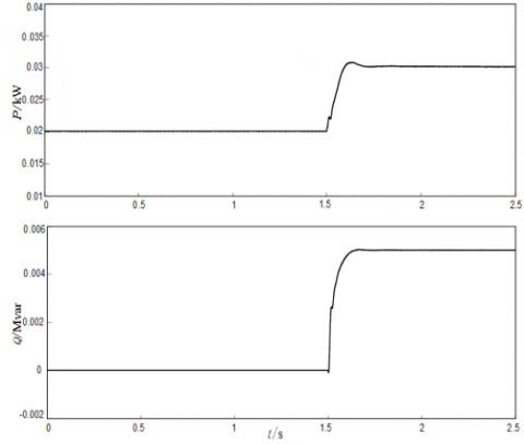
In the VSG island state of the photovoltaic array, the electrical energy generated by the photovoltaic array is used by the load, and the battery does not operate; when the load changes, the battery cooperates with the output power of the photovoltaic array to maintain a stable DC bus voltage. Set the local load to 20kW+0Var, the battery state of charge to 65%, and the simulation time is 2.5s. The initial light intensity is 700W/m2, when t=0.5s, the light suddenly increases to 1100W/m2, the light returns to the original initial light intensity at 1s, and the load is increased by 10kW+5kVar at 1.5s. During this process, the output power of the photovoltaic unit and battery is shown in Figure 10(a). When 400W/m2 is increased from 0.5s to 1s, the photovoltaic output power increases from 20kW to 25kW, which is greater than the reference value Pref, and the battery is quickly charged at this time; after 1.5s, the battery is quickly discharged to maintain power balance, as shown in Figure 10(b). Figure 10(c) shows the DC bus voltage waveform, which is stable at 800V under the action of the battery. VSG output active power, reactive power waveforms are shown in Figure 10 (d).
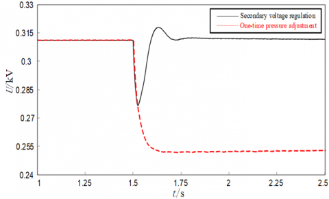
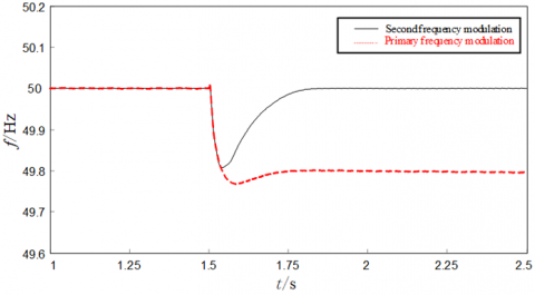
Take the waveform diagram of the system frequency and voltage amplitude in the 1s~2.5s time period during the whole simulation process. It can be seen from Figure 11 (a) and (b) that due to the primary frequency modulation capability of the VSG, when t=1.5s, as the load power increases, the frequency and voltage amplitude both drop to the new steady-state value. The frequency and voltage amplitude offset of the optical storage VSG gradually decreases under the action of the secondary frequency modulation and voltage regulation, and returns to the original rated value state. The simulation result verifies the correctness of the secondary frequency modulation and voltage regulation.
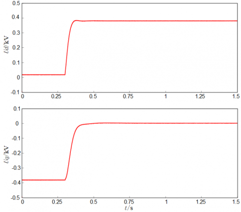
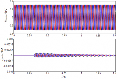
When the output frequency and voltage amplitude of the optical storage VSG in island mode are consistent with the grid frequency and voltage amplitude, then phase pre-synchronization is performed. Close the switch S5 in Figure 9, the output voltage of the optical storage VSG is decomposed by dq, the d-axis component ud increases to 380V, and the q-axis component uq increases to 0V, as shown in Figure 11(c); the VSG output on both sides of the grid point PCC The voltage and phase gradually coincide with the grid side voltage and phase, as shown in Figure 11(d), at which time phase synchronization is completed. The simulation results verify the effectiveness of phase synchronization in phase difference detection.
(a) Photovoltaic unit and battery output power
(b) Battery state of charge
(c) DC bus voltage
(d) VSG output power waveform
Figure 10. Waveform diagram of optical storage VSG under island
(a) Secondary frequency modulation
(b) Secondary pressure regulation
(c) Ud and Uq waveform
(d) Phase and voltage waveforms on both sides of the grid
Figure 11. Waveforms of pre-synchronization under the optical storage VSG island
(a) VSG outputs three-phase voltage and current waveforms
(b) Three-phase voltage and current waveforms on the grid side
Figure 12. Waveform diagram of optical storage VSG isolated/grid-connected seamless switching
Figure 12 (a) and (b) are the simulation waveform diagrams of the three-phase voltage and current on both sides of the grid connection point after the optical storage VSG is switched from island to grid connection.
After the frequency, phase, and voltage amplitude on both sides of the grid are synchronized, the optical storage VSG switches from island mode to grid-connected mode within 0.3s, as shown in the simulation results of Figure 11 (a) and (b), the optical storage VSG at the moment of grid-connected The VSG output three-phase voltage and current and the grid-side three-phase voltage waveform have no obvious fluctuations. The grid-side output three-phase current waveform does not exceed 2A when the impulse current is 0.3s. The simulation results verify that the proposed pre-synchronization method can successfully achieve grid connection.
Under the background of optical storage VSG DC microgrid in island mode, a pre-synchronization control strategy based on secondary frequency modulation and voltage regulation is proposed, which aims at the large inrush current problem of the optical storage VSG inverter at the moment of off/grid switching. By performing secondary frequency modulation and voltage regulation under the isolated grid, and phase tracking according to the phase difference detection link, the problem that the optical storage VSG cannot be smoothly connected to the network is solved. This scheme effectively reduces the inrush current at the moment of grid connection, can successfully complete the grid connection operation, and provides an effective solution for the grid connection of distributed power sources such as photovoltaics. The simulation results verify the effectiveness and correctness of the pre-synchronization control strategy based on secondary frequency and voltage regulation.
[1] Zheng, T.W., Chen, L.J., Chen, T.Y., Mei, S.W. (2015). Review and prospect of virtual synchronous generator technologies. Automation of Electric Power Systems, 39(21): 165-175. https://doi.org/10.7500/AEPS20150508006
[2] Chen, Y., Hesse, R., Turschner, D., Beck, H.P. (2011). Improving the grid power quality using virtual synchronous machines. In 2011 International Conference on Power Engineering, Energy and Electrical Drives, pp. 1-6. https://doi.org/10.1109/PowerEng.2011.6036498
[3] Ding, M., Yang, X.Z., Su, J.H. (2009). Control strategies of inverters based on virtual synchronous generator in a microgrid. Automation of Electric Power Systems, 33(8): 89-93. https://doi.org/10.3321/j.issn:1000-1026.2009.08.019
[4] Lv, Z.P., Sheng, W.X., Zhong, Q.C., Liu, H.T., Zeng, Z., Yang, L., Liu, L. (2014). Virtual synchronous generator and its applications in micro-grid. Proceedings of the CSEE, 34(16): 2591-2603. https://doi.org/10.13334/j.0258-8013.pcsee.2014.16.009
[5] Shi, R.L., Zhang, X., Xu, H.Z. (2016). Seamless switching control strategy for microgrid operation modes based on virtual synchronous generator. Power System Automation, 40(10): 16-23. https://doi.org/10.7500/AEPS20150615012
[6] Chai, L., Li, L., Li, B., Wang, H. (2019). Strategy of pre-synchronized grid-connection based on improving virtual synchronous generator. Renewable Energy Resources, 37(7): 1015-1020. https://doi.org/10.3969/j.issn.1671-5292.2019.07.012
[7] Wan, X., Zhan, Z., Liao, Z. (2018). Research on seamless switching strategy of virtual synchronous generator. Journal of Electronic Measurement and Instrumentation, 32(5): 33-40. https://doi.org/10.13382/j.jemi.2018.05.005
[8] Hu, S., Yuan, X.F., Zhu, Y.L., Gao, Z.P., Li, Z.X. (2018). Research on seamless switching control technology of micro-grid operation mode. Electrical Measurement & Instrumentation, 55(17): 56-61, 67. https://doi.org/10.3969/j.issn.1001-1390.2018.17.010
[9] Wei, Y.L., Zhang, H., Sun, K. (2016). Pre-synchronization method of virtual synchronous generator using virtual power. Pre-synchronization Method of Virtual Synchronous Generator Using Virtual Power, 40(12): 124-129. https://doi.org/10.7500/AEPS20150727006
[10] Cheng, Z.X., Yu, Y., Chai, X.Z. (2020). Research on operation control of a photovoltaic system with storage VSG based on cooperative adaptive control. Power System Protection and Control, 48(24): 79-85. https://doi.org/10.19783/j.cnki.pspc.200038
[11] Bai, W., Liu, L.Q., Zhang, C.M., Ma, L.Q. (2017). Seamless switching control technology of virtual synchronous generator. Process Automation Instrumentation, 38(12): 13-17. https://doi.org/10.16086/j.cnki.issn1000-0380.201712004
[12] Wang, J.S., Tang, C.H., Chen, N., Tan, K., Mao, J.X. (2015). A method of microgrid connecting and off-grid smooth switching control based on running mode self-identification. Automation of Electric Power Systems, 39(9): 185-191. https://doi.org/10.7500/AEPS20140521004
[13] Yan, X.W., Wang, D.S., Jia, J.X. (2019). Non-communication pre-synchronization scheme of vsgs based on decentralized microgrids. Transactions of China Electrotechnical Society, 34(19): 4143-4153. https://doi.org/10.19595/j.cnki.1000-6753.tces.L80765
[14] Ji, Y., Su, J., Ding, B. (2021). Research about off/on Micro-grid virtual synchronous generator switching control strategy under grid fault. Control Engineering of China, 28(7): 1496-1504. https://doi.org/10.14107/j.cnki.kzgc.20190522
[15] Li, B., Zhou, L., Yu, X.R. (2017). Secondary frequency regulation for microgrid inverters based on improving virtual synchronous generator. Power System Technology, 41(8): 2680-2687. https://doi.org/10.13335/j.1000-3673.pst.2016.3224