Padmasree L | Preethi Eluri* | Sai Subrahmanya Akhil Badampudi | Sreedhar Reddy Mukkamalla
© 2020 IIETA. This article is published by IIETA and is licensed under the CC BY 4.0 license (http://creativecommons.org/licenses/by/4.0/).
OPEN ACCESS
With the increase in vehicle accidents regularly, there is a need to control these accidents and save precious lives. The main reason for accidents on roads are mainly observed by driver misconception, recklessness and over speeding. So, there is a need to develop a Vision system which has a ability to explore its surroundings and move accordingly. The Vision system is divided into 3 subsystems as Visual perception subsystem, Brake and Acceleration subsystem and Steering control subsystem. The Visual perception means the ability to interpret surrounding environment using light in the visual spectrum reflected by the objects in the environment. This subsystem uses distance measuring sensors such as Light Detection and Ranging (LiDAR) and Ultrasonic sensors for detecting objects and sends the data to brake and acceleration subsystem using Arduino IDE software. According to the data received either the brake or acceleration is initiated, it means that when the distance measuring sensor values reach the threshold values then the brakes are applied or else acceleration is implemented.
In order to have a smooth ride the acceleration should be uniform without any jerks though speed changes. This is resolved by using Proportional-Integral- Derivative (PID) controller which reduces the gradual difference between the desired and input speed. The Steering control subsystem involves lane detection and path tracking. The lane detection is done using Python and OpenCv which uses various image processing steps, gives the steering angle by calculating the curvature radius of lanes. Therefore path tracking system is initialized taking the steering angle and direction as input for controlling the position of the vehicle.
LiDAR, visual perception, lane tracking, path tracking, PID
More than 90 per cent of road deaths in 2016 were attributed to rash and negligent driving, with the latest National Crime Research Bureau (NCRB) statistics revealing 1.5 lakh deaths in accidents due to delinquent driving. An autonomous vehicle is competent of sensing its environment and navigating without human input. The autonomous car has been a dream for mankind for a long time. The brief history of autonomous vehicles and its levels of automation were discussed by Seetharaman et al. [1]. Everything is controlled by various electronic devices which may be a small IC or micro controller or microprocessor. It requires understanding the various electronic systems and their interface with automotive systems.
The main perception of Vision system relies on sensors which senses objects in front and brake or accelerate when needed. In this process, the vehicle is controlled using cruise control process, which has detailed explanation using PID controllers [2, 3]. Ben Romdhane et al. [4], Davis [5], and Pawlicki [6] have developed a prototypes for lane and path tracking, cruise control and object detection. The Visual perception works based on the TFmini LiDAR, ultrasonic ranging technique, and speed from the speed sensor. The brake and acceleration applied in accordance with the range of these sensors, and actuators. Steering control depends upon the speed of the vehicles, the curvature of the road, or the turning radius and on the banking of the road also. Cameras were used to detect the lanes and then processed by controller in car as explained by Assidiq et al. [7]. There are 2 main parts in detecting lanes - image enhancements followed by edge detection. The lane shape and curvature are detected by the set of coordinates which are generated by the Edge detection. Brake and Acceleration depend on the Visual perception and speed of the vehicle. The speed is calculated by an inductive proximity sensor on the front wheel. For the visual perception LiDAR sensor was selected based up on its features presented by Spinhirne [8]. The Structure of this paper is as follows: The Implementation of this system is explained in detail in Section 2. In Section 3 the functional process of system is presented, while in Section 4 the experimental results are shown and Section 5 concludes the paper.
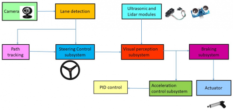
This paper shows work on different subsystems of an autonomous vehicles. The Block diagram of the Vision system is represented in the Figure 1 explains about the complete working of the different subsystems in it. To begin with, the camera installed in the vehicle captures the images of the road, detects the lanes through lane detection and the path of the vehicle in the lane is traced by path tracking. Besides path setting, vehicle checks the presence of obstacles, using ultrasonic and LiDAR sensor’s, and applies acceleration or brake as per its necessity.
Figure 1. Block diagram Each system works with various techniques
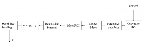
Figure 2. Process of lane detection
2.1 Steering control subsystem
The steering Control subsystem involves lane detection and path tracking as it is very crucial to locate the vehicle and to track its position on the road.
1) LANE DETECTION: Lanes were detected using a combination of Canny edge and Hough transform. The process of lane detection is shown in Figure 2. The lane detection should now account for the shape and curvature of the road. The information captured should be accurate enough to convert into real world units such as meters. It should be able to determine the relative position of the car with respect to lanes and make informed decisions to improve the overall accuracy. So as to achieve this there are two parts -image enhancement and edge detection. Before any transformations Camera calibrati on is done to correct optical distortion, if any. A very easy method to correct distortion is using the openCV library. It is used to calculate a distortion matrix and then calibrate the images based on the matrix. Then the edge detection is done using canny’s operator, the equation for maxima is given as
$G_{\sigma}=\frac{1}{2 \prod \sigma^{2}} \exp \left[\frac{x^{2}+y^{2}}{2 \sigma^{2}}\right]$ (1)
The Hough transform intercepts the lines obtained from edge detection using the slope-intercept formula:
$y=m x+c$
2) PATH TRACKING: The path tracking system is capable of controlling the steering using stepper motor based on the steering angles obtained from lane detection. The output of the lane detection gives the continuous direction and angle for the arduino. The arduino controls the steering movement, setting the steering to move in the required position. Initially, the controller centers the steering position to the zero, and then steers to the calculated steering angle.
2.2 Visual perception subsystem
The development of visual perception subsystem includes TFmini LiDAR, Ultrasonic sensors, controller and the linear actuator. In order to cover large area, a servo motor is attached to the LiDAR, which detects the obstacles along the ultrasonic sensors. The LiDAR and the ultrasonic sensor send the received signals to the arduino which analyses the input signal and instructs either the actuator when there is obstacle or the acceleration when there is no obstacle. The actuator works by relay switching from one position to another if the sensors values are less than or equal to the threshold.
2.3 Brake and acceleration subsystem
As mentioned earlier, the braking system depends on the output of the sensor values so as to enable the linear actuator. The acceleration is done by taking into account the speed of the motor. The speed of a motor is influenced by the voltage.
So if the speed of the motor increases, then there will be an increase in voltage. But for an electric car, the voltage of a DC engine is constant, the speed will be constant as long as no elevation appears. Within the case of changing slope, the voltage also be changed to assure constant speed. To manage the speed of a DC motor there is a need to live the particular speed, this is done by using the inductive proximity sensor at the front wheel, which gives the rounds per minute called as "rpm". After this the target speed is defined as "Set point". If rpm is higher than the set point then the voltage should be lower and if the rpm is lower than the set point then the voltage should be higher. The difference between the set point and the rpm is called Error. As PID controller controls the desired speed by closed loop operations without any sudden jerk of the vehicle. PID.h library is included which has the inbuilt functions to maintain the desired output by P, I, D controllers acting individually. As the brake and acceleration needs to be interlinked as they either send information to other systems or devices. So an I2C Communication is established making the object detection – brake algorithm as Master and Acceleration algorithm as Slave.
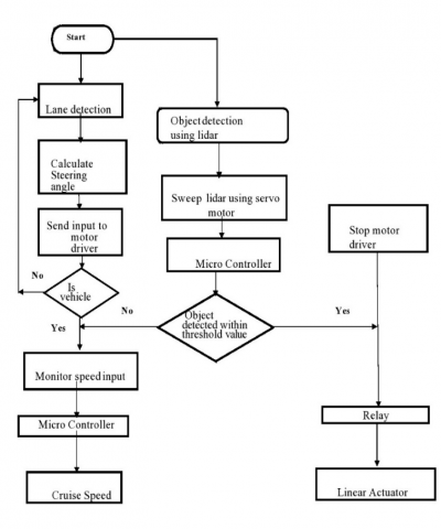
The functional process of the system is illustrated using the flowchart as shown in Figure 3. The vehicle starts by checking the position of the vehicle with respect to lane and object detection. The position of the vehicle is known by calculating the steering angle, system will check the obtained angle with the desired angle, if desired angle and obtained are same then acceleration can be initiated else the input should be given to motor to set the angle of the steering.
The object detection is done by using LiDAR and ultrasonic sensor, the obtained distances is compared with desired threshold values, if obtained value is greater than desired then the brake is applied with the help of linear actuator and the vehicle decelerates else acceleration is applied.
Figure 3. Work process of the vision system
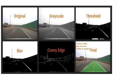
The advancement of technology led to the safety of the vehicle and it relies predominantly on the sensors that accelerate, decelerate the vehicle, and the steer angle that controls steering of the vehicle. Each system was tested individually as a unit, in view of its ultimate purpose. By independent testing, any errors in the module were worked out and solved before integration. Each module was developed iteratively, with each iteration meeting the requirements and designed goals. The original input image is captured and the conversation to grey scale is done. This grey scaled image is then passed through the color threshold filter and blur is added to it. The canny edge detection is done and the image is then converted from normal view to bird's eye view. The sliding window detects the left and right sides of lane by dividing it into small windows. The vehicle offset is found by detecting the Centre of road and comparing with center of vehicle. The curvature is found from the position different between the points on the road which are selected from the lane.
The original image with different preprocessing techniques is as shown in Figure 4.
Figure 4. Lane detection using Hough transform
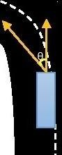
The calculated steering angle (Ɵ) and direction is given as input for the path tracking and the vehicle is made to move accordingly as shown in Figure 5. For example if the input angle is obtained as 30 degrees, left direction from the lane detection then the steering is made to rotate to the specified angle and direction from zero degrees i.e. at center position. Incase if there is another angle detected in different direction within the time limit of executing the first angle then the steering position is set to zero and then rotates to the second angle.
Figure 5. Measuring steering angle
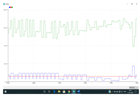
The simulation results of the acceleration is as shown in Figure 6. The red line represents the constant target speed of 10kmph. The blue line shows the fluctuations in the speed of the vehicle while going up and down. In other words, the speed values are greater than the target speed indicates the vehicle is going down and speed values less than the target speed indicates the vehicle is going up. The green line represents the output limits of a PID controller.
Figure 6. PID simulation graph
In this paper, we have discussed about the development and implementation of the vision system. The lane detection using OpenCV has given an effective result which is most important for the path tracking. An extensive analysis was done to check the efficiency of braking and acceleration. A good communication system has established between brake- acceleration and visual perception subsystems. The provided results show that the vision system discussed in this paper with various systems has an ability to drive its own.
This work is supported by the VNR Vignana Jyothi Institute of Engineering and Technology and faculty members of Automobile Engineering department.
[1] Seetharaman, G., Lakhotia, A., Blasch, E.P. (2006). Unmanned vehicles come of age: The DARPA grand challenge. Computer, 39(12): 26-29. https://doi.org/10.1109/MC.2006.447
[2] Pan, Z., Bao, H., Pan, H., Xu, C. (2016). An intelligent vehicle based on an improved PID speed control algorithm for driving trend graphs. International Journal of Simulation--Systems, Science & Technology, 17(30): 1-7. https://dx.doi.org/10.5013/IJSSST.a.17.30.19
[3] Zhong, J. (2006). PID controller tuning: A short tutorial. Mechanical Engineering, Purdue University, 1-10.
[4] Ben Romdhane, N., Hammami, M., Ben-Abdallah, H. (2011). A lane detection and tracking method for driver assistance system. In: König A., Dengel A., Hinkelmann K., Kise K., Howlett R.J., Jain L.C. (eds) Knowledge-Based and Intelligent Information and Engineering Systems. KES 2011. Lecture Notes in Computer Science, vol 6881. Springer, Berlin, Heidelberg. https://doi.org/10.1007/978-3-642-23851-2_42
[5] Davis, L.C. (2004). Effect of adaptive cruise control systems on traffic flow. Physical Review E, 69(6): 066110. https://doi.org/10.1103/PhysRevE.69.066110
[6] Pawlicki, J.A. (2006). Object detection system for vehicle. U.S. Patent No. 7,038,577.
[7] Assidiq, A.A., Khalifa, O.O., Islam, M.R., Khan, S. (2018). Real time lane detection for autonomous vehicles. 2008 International Conference on Computer and Communication Engineering, Kuala Lumpur, pp. 82-88. https://doi.org/10.1109/ICCCE.2008.4580573
[8] Spinhirne, J.D. (1993). Micro pulse lidar. IEEE Transactions on Geoscience and Remote Sensing, 31(1): 48-55. https://doi.org/10.1109/36.210443