Marcin Bocheński* | Jarosław Gawryluk | Łukasz Kłoda
OPEN ACCESS
In this study, a modal analysis of an active thin-walled composite box-beam is performed using different research methods. The box-beam was made of several unidirectional carbon-epoxy layers. The configuration of the composite plies enabled obtaining the expected bending-bending or bending-torsion vibration coupling. A Macro Fiber Composite (MFC) element was added to the structure. MFC elements can be used as a source of external excitation or actuator for a vibration control algorithm. Three experimental methods are applied. First, an experimental modal analysis based on impact testing is performed, in which the structure is excited by a modal hammer and its response is measured by an accelerometer. Second, the structure is excited using an electromagnetic shaker or an MFC actuator, and simultaneously its response is measured by a laser vibrometer. Third, the structure is excited with the MFC actuator during the recording of the structure’s dynamic response using an optical 3D measuring system. The impact of the applied methods on the extracted shape modes and natural frequencies is investigated. Additionally, the efficiency of MFC operation is tested for selected modes. The experimental findings are compared with the numerical results obtained by the finite element method (FEM).
finite element method, impact testing, laser vibrometer, optical 3D measurements, coupled vibrations
Thin-walled box-beam structures made of composite materials are widely used in engineering applications, e.g. as arms of robots, antenna supports, helicopter blades or aircraft wings. They are lightweight materials, and their properties can be shaped at the stage of fabrication. The accurate characterization of their dynamical properties is very important, especially for health monitoring and active vibration control applications [1]. Different theoretical methods can be used but always some kind of experimental validation is needed. The dynamical response of beam-like structures can be measured using contact and contactless methods as well as internal (e.g. by piezo-actuators fixed to the structure) and external excitation sources. The impulse technique was used, wherein the force was applied by an impact hammer and the response was measured using a small piezoelectric accelerometer attached to the beam’s tip [2]. The coupling effect of rotary inertia, shear deformation and root flexibility on the beam’s natural frequencies and mode shapes was investigated. A similar experimental method is described by Rand [3]. The blades were excited by an external force impulse during rotation. The time history of the resulting strain distributions using strain gauges was recorded. The rotating thin-walled composite blades were mounted in a vacuum chamber to isolate the structural dynamic effects. Moreover, symmetric and antisymmetric box-beam specimens were tested. In the study of Minguet and Dugundji [4], the dynamic behaviour of structurally coupled graphite-epoxy composite blades was investigated. Axial and 45º-angled strain gauges were used for the identification of bending and torsion modes, respectively. Because of large deflections, the electromagnetic shaker was connected to the blade with a soft spring. But when the structure began to show a more complex dynamics (higher modes), the number of strain gauges had to be increased. Therefore, the strain gauges were attached from 6 to 12 critical locations of the beam [5]. In recent years for this type of structures piezoelectric devices have been widely used. They are popular because of high strength, temperature insensitivity and facility of implementation. Bending and torsional vibrations of flexible structures are measured and actuated by properly distributed piezoelectric sensors and actuators [6]. In the study of Zehetner et al. [7], 48 piezoelectric patches were attached to a beam with a rectangular hollow cross-section. Each patch could be used as an actuator or a sensor. Additionally, the authors used strain gauges and accelerometers. In another research, PVDF and MFC transducers were integrated into a composite structure for their active modal control [8]. Moreover, the experimental identification was based on a curve fitting approach using the measured frequency response functions (FRFs). Also, two shakers and accelerometers were employed to identify the structure’s parameters. In the study Nestorovic et al. [9], where four piezoelectric elements were used as actuators, the response of the beam was measured using a laser Doppler vibrometer. A similar method is presented by Beck et al. [10], but the thin aluminium beam was equipped with 24 piezo-elements. The structure’s response was measured by a scanning laser head at 125 equally spaced locations along the length of the beam.
Experimental results are often compared with analytical or numerical findings. Behera et al. [11] used system consist of a modal hammer, piezoelectric accelerometer and spectrum analyser to determine the first three shape modes and natural frequencies of cracked aluminium free-free beam structure. Experimental results are used to verification of a proposed hybrid intelligent model to detect of crack depth and location. The most popular numerical method is finite element method [12, 13]. The FEM analysis and experimental tests of the composite structure with an MFC active element were performed by Latalski et al. [14]. Gawryluk et al. [15] present a numerical and experimental analysis of an active composite beam. The FEM validation of the MFC active element is described. Teter and Gawryluk [16] performed an experimental and numerical modal analysis of a rotor with three active blades. The experimental setup consisted of the LMS suite of data acquisition system and a laser vibrometer. The results of a numerical modal analysis of the aluminium beam with and without piezoelectric patches were reported by Sartorato et al. [17]. The FEM results were compared with the experimental data. The numerical direct piezoelectric effect on a composite beam with an external load applied to the free end of the piezoelectric composite beam was investigated by Nechibvute et al. [18].
In this study, a modal analysis of an active thin-walled composite box-beam is performed using different research methods. Bending-bending and bending-torsion vibration couplings are examined using impact testing, a scanning laser vibrometer and an optical 3D measuring system. The influence of the applied methods on the extracted shape modes and natural frequencies is determined. The experimental results are compared with the FEM numerical results.
The object of this analysis is a thin-walled cantilever box-beam made of carbon-epoxy unidirectional tape manufactured by North Thin Ply Technology and based on fibers M40JB-12K50B provided by Toray Carbon Fibers America [19]. The lamination process is followed the NTPT ThinPreg 513 data sheet. Fiber volume is equal 57%.
Three configurations of the composite plies are examined:
(1) [75/75/75/90/-75/-75/-75]T CAS (circumferentially asymmetric stiffness) - where the structure’s vibrations are decoupled to two independent couplings - flapwise bending with torsion and chordwise bending with extension,
(2) [75/75/75/90/75/75/75]T CUS (circumferentially uniform stiffness) - where the structure’s vibrations are decoupled to two independent couplings - flapwise bending with chordwise bending and torsion with extension,
(3) [90/90/15/15/15/15/90/15/15/15/15/90/90]T CAS.
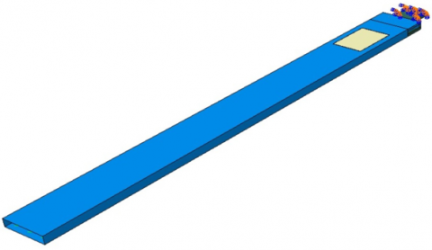
The shape mode coupling is caused by the layers oriented in the directions 15º and 75º (with respect to the beam axis) [20]. The layers defined by the angle of 90º are necessary from a technological point of view. The external dimensions of the beams are 80x20x900 mm, and the thickness of the beam wall depends on the number of layers - one layer width equals 0.057 mm. The physical properties of the applied material are as follows: Young’s modulus: longitudinal - 143.2 GPa, transverse - 3.1 GPa; Poisson’s ratio - 0.35; shear modulus - 3.38 GPa; mass density - 1442 kg/m3. The S8R shell elements with reduced integration were used for the model of the beam. On the beam surface the MFC M-8557-P1 actuator manufactured by Smart Material Corp., USA was installed. This device utilizes the d33 effect for actuation, which corresponds to the deformation of a specimen in the direction of a driving electric field.
The FEM model of actuator was constructed using the C3D20E type solid elements. They were 20-node second order elements, having three translational degrees of freedom at each node and one extra degree of freedom associated with the piezoelectric properties. This type of elements allows us to model the effect of electromechanical coupling. The numerical model of this active element was validated according to the test described in the papers [15, 16, 21]. Next, electrical properties of the transducer were determined. The optimal value of the d33 constant for this element was set to 9.8*10-8 m/V. The mechanical properties of macro fiber composite elements are specified on the manufacturer’s website. The numerical model of the blade handle was built using the C3D20R solid elements. These are 20-node second order elements (with a square shape function), having three translational degrees of freedom at each node. These elements used a reduced integration method (Figure1). The handle of the beam was made of aluminium alloy.
Figure 1. The FEM model of box-beam
Individual layers of the laminate were made according to the Layup-Ply technique. The mechanical boundary conditions of this model were defined by restraining the nodes located on the foundation of all degrees of freedom. The combination of all elements was realized by defining the interactions as tie. It is the Abaqus function which ties two surfaces together for the duration of a simulation.
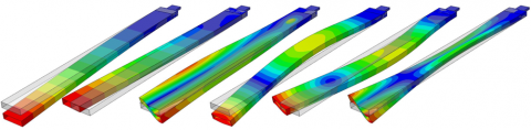
A surface-based tie constraint can be used to make the translational and rotational motion as well as all other active degrees of freedom equal for a pair of surfaces. The simulations were performed by the finite element method using the commercial Abaqus system. The numerical modal analysis of the structure was performed. The natural frequencies and the corresponding shape modes of free vibrations of the system were determined using the Lanczos method. Six modes were taken into account (Figure 2). They were, starting from the left, the first flapwise bending mode, the first chordwise bending mode, the first torsional mode, the second flapwise bending mode, the second chordwise bending mode and the second torsional mode.
Figure 2. The analysed shape modes
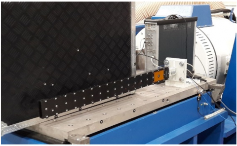
All experimental tests were conducted in a laboratory of the Department of Applied Mechanics at the Lublin Centre for Technology Transfer, Lublin University of Technology. The blade was fixed by the handle to the anti-vibrational TIRA TGT MO 48 XL table (Figure 3). The white dots are the reflective markers that were used for optical measurement systems. They allow to decrease the exposure time and improve the reflection of laser beam. The experiments were carried out using the following instruments:
• LMS SCADAS III modal analyser with PQA II data acquisition card, PCB Piezotronics modal hammer model 086E80, 352M208 accelerometer and TestLab 10B software,
• Polytec PSV-500 laser vibrometer system,
• PONTOS HS stereo camera system and PONTOS Live and GOM Correlate software,
• SmartShaker™ K2007E01 electromagnetic shaker with PCB Piezotronics 208C01 force sensor,
• Smart Material HVA1500-3 high voltage amplifier,
• Macro Fiber Composite M-8557-P1.
Figure 3. The view of laboratory specimen
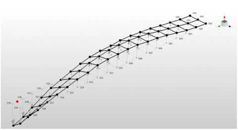
The modal analysis was based on FRFs between the excitation force generated by the hammer in one point of the structure and the response measured by the accelerometer in another point. There can be done using moving input (excitation point is changing) or moving output (position of the sensor is changing). 54 measuring points were marked on the tested structure (Figure 4). The points on the central line were excited only in the “Z” direction, while for the points on the side lines two directions were available - “Z” and “Y”. The position of the sensor is described by a grey marker between points 118 and 119. Each point was excited to averaging five times, taking into account two directions for the side lines, and the shape modes were calculated based on the results of 450 excitations.
The second method was a contactless technique involving the use of a laser beam. The Doppler effect and phase shift were used to determine velocity of the object [22, 23]. The relationship between the measured and emitted frequencies is described by Eq. (1) [24].
$f=\frac{c+v_{r}}{c+v_{s}} f_{0}$ (1)
where:
c - velocity of the waves in the medium,
f0, f - emitted and observed frequency, respectively,
vr - the velocity of the receiver relative to the medium; positive if the receiver is moving towards the source,
vs - the velocity of the source relative to the medium; positive if the source is moving away from the receiver.
The laser head is equipped with a laser source, laser sensor and video camera. This approach allows for continuous measurement of the value of velocity of the scanned points perpendicular to the vibrometer's head (direction Z). Furthermore, the time courses of displacement and acceleration can be calculated by the multiplication of direct proportionality constants. The laser head is connected to the data acquisition and visualization unit generating the excitation signal to the electromagnetic shaker or piezo-amplifier. Moreover, the applied software allows us to analyse natural frequencies and their shape modes. One head enables measurements in the laser beam direction. To make measurements in the flapwise and chordwise direction, a change of the head position is necessary. The 2D scanner head was located 2 m opposite the beam-box to embrace the entire measured surface (Figure 3). The aperture angle of the external points was smaller than 12.5°, therefore the angle correction of measurements was applied. The excitation was loaded using the MFC or SmartShaker by a periodic chirp voltage, its amplitude being set to 20 V and 0.1 V, respectively. The bandwidth was defined from 0 to 1 kHz with 12800 FFT lines. In the modal analysis, each point was measured three times to get average results, and correction filters were used. The signal was received as speed change over time. Using a fast Fourier transform (FFT) the signal was converted in the frequency domain. The analysis revealed the frequencies and modes of the tested structure in the defined points. The resonances are marked as peaks corresponding to frequencies. The results are illustrated as the plots of velocity distribution of the test points or its converted values of displacements and accelerations with phase shift taken into account (Figure 5).
Figure 4. Second flapwise bending mode obtained from LMS
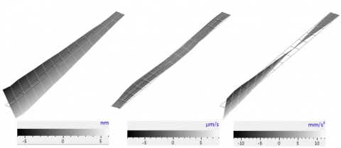
Figure 5. First torsion mode obtained with the laser vibrometer (displacement, velocity and acceleration, respectively)
The PONTOS system uses two cameras, each with a relatively small resolution of 1.3 Mpix, but due to the application of a special software algorithm, the system ensures a practical measurement accuracy higher than 0.1 pixel. Taking into account the dimensions of the analysed structure, the real measurement error is 0.06 mm. To ensure high accuracy, the system was calibrated using a special pattern which helps to eliminate all optical errors of the measuring chain. The use of stroboscopic lighting synchronized to the cameras and special markers glued to the analysed structure (Figure 3) ensured a short shutter time and prevented a ghosting effect. The use of full-frame of cameras ensures the recording speed of 500 Hz but, taking into consideration the dimensions of the beam (high length and relatively small height), a half-frame camera was used. Therefore, it was possible to apply the recording speed of 1 kHz. The structure was excited in a sequence using the natural frequencies obtained from the LMS and laser vibrometer systems, and a dynamical response using PONTOS HS system was observed. Next, 3D shape modes were extracted (Figure 6).
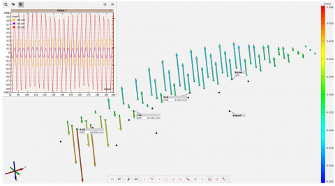
Figure 6. Second flapwise bending mode obtained from PONTOS HS
The natural frequencies obtained for the tested composite box-beam are listed in Table 1. Two experimental methods were used to validate the FEM numerical results: an experimental modal analysis based on impact testing and a contactless measurement method by a laser vibrometer. Three configurations of the composite plies were taken into account (Section 2). Shape modes 1-6 are presented in Figure 2. Generally, a good agreement between the numerical and experimental values can be observed. However, significant differences can be noticed, especially with respect to beam A in the second as well as the fourth mode. This may result from the fact that beam A was excited by the electromagnetic shaker, while the excitation of beams B and C was generated using the MFC actuator.
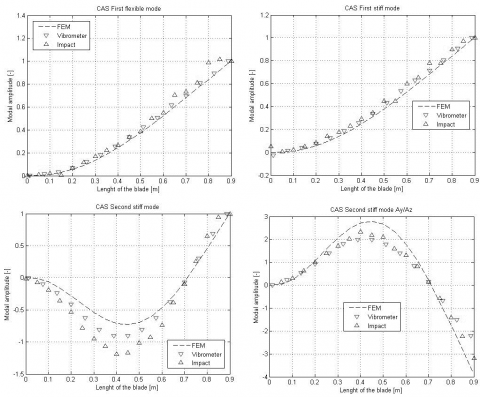
The shape modes were extracted, and the displacements in the flapwise (flexible) and chordwise (stiff) direction were calculated. These amplitudes were normalised taking into account the amplitude of the beam’s free end displacement in the flapwise direction. In addition, the coupling between the chordwise and flapwise bending modes was tested and the amplitude ratios Ay/Az were calculated. A selection of the obtained results is given in Figures 7 and 8.
Table 1. Extracted natural frequencies [Hz]
|
|
Beam A |
Beam B |
Beam C |
||||||
|
|
FEM |
Impact |
Laser |
FEM |
Impact |
Laser |
FEM |
Impact |
Laser |
|
mode 1 |
11.75 |
13.82 |
13.41 |
27.22 |
24.42 |
24.88 |
33.86 |
36.30 |
36.88 |
|
mode 2 |
33.68 |
42.40 |
38.13 |
78.13 |
74.62 |
76.68 |
98.37 |
95.86 |
96.41 |
|
mode 3 |
208.18 |
218.39 |
------- |
215.92 |
217.74 |
221.20 |
339.68 |
300.47 |
302.00 |
|
mode 4 |
69.13 |
85.69 |
67.47 |
148.32 |
138.33 |
139.00 |
186.60 |
189.76 |
194.20 |
|
mode 5 |
200.22 |
259.94 |
243.20 |
438.43 |
422.41 |
428.50 |
540.36 |
528.77 |
531.70 |
|
mode 6 |
232.18 |
254.07 |
294.00 |
328.51 |
317.58 |
323.70 |
514.31 |
435.94 |
429.70 |
Figure 7. Experimental and numerical shape modes comparison - beam A
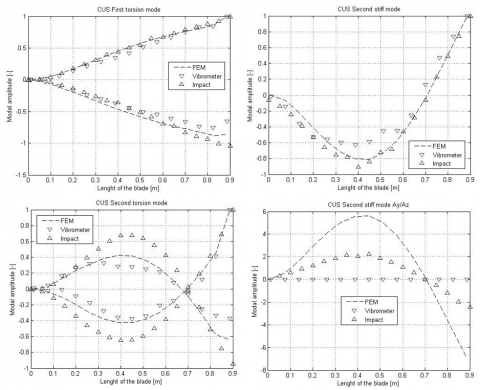
Figure 8. Experimental and numerical shape modes comparison - beam B
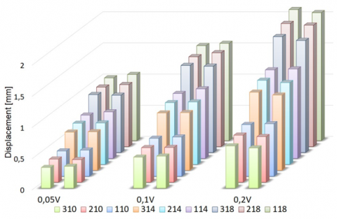
Figure 9. Displacement of the selected points of the beam C obtained with the laser vibrometer (left column) and with the PONTOS system (right column)
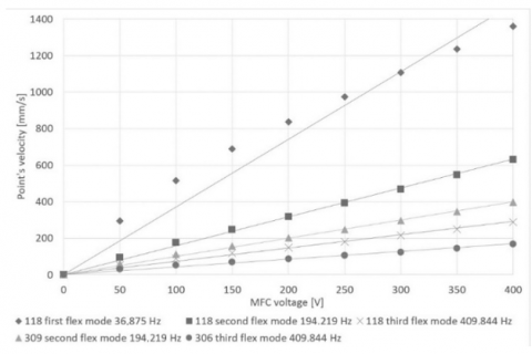
Figure 10. Selected point’s velocity versus MFC voltage - beam C
The best agreement can be observed for the first modes: flapwise, chordwise and torsion. However, the second modes visibly differ. This is due to the fact that there is a significantly smaller amplitude of vibration and a higher relative error value. The biggest differences are observed for the Ay/Az ratio computed with the laser vibrometer, where the measurements of stiff deflection lead to a change of the laser head position. Figure 9 shows the amplitudes of displacement for selected points of the box-beam in the C configuration when the first flapwise bending mode is excited. This configuration is the most difficult from the measuring point of view due to the highest stiffness and thus the smallest amplitudes of vibrations. Three amplitudes of excitation were generated by the electromagnetic shaker corresponding to the following voltage levels: 0.05, 0.1 and 0.2 V. The vertical axis describes the displacement in millimetres. The left column represents the results obtained with the laser vibrometer while the column on the right shows the results obtained with the PONTOS system. Regardless of excitation amplitude, only minor differences are observed. Moreover, the efficiency of the MFC actuator in exciting three flapwise bending modes was examined. The response was measured in selected points using a laser vibrometer. The MFC voltage amplitude was varied from 0 to 400 V. It was found that the vibration amplitude increases linearly with increasing the voltage (Figure 10). A clearly regressive characteristic is observed only for the first mode.
This study involved performing a modal analysis of an active thin-walled composite box-beam using different research methods. Natural frequencies and shape modes were extracted. The experimental findings were compared with the FEM results. Generally, the numerical and experimental values show a good agreement. Nonetheless, the laser vibrometer results are closer to those obtained by other methods when the structure is excited by the MFC actuator. The results have revealed a significant effect of the electromagnetic shaker connected to the structure by an axially stiff adaptor on the selected natural frequencies and shape modes. The influence of the sensor’s weight used in the impact tests (smaller than 1 gram) on the tested structures is negligible. The study has demonstrated that even one MFC M-8557-P1 actuator can be an effective source of excitation for the tested box-beam.
The research is supported by the Polish National Science Center, research grant No. DEC-2012/07/B/ST8/03931.
[1] Manoach, E., Warmiński, J., Kłoda, Ł., Teter, A. (2017). Numerical and experimental studies on vibration based methods for detection of damage in composite beams.Composite Structures, 170: 26-39. https://doi.org/10.1016/j.compstruct.2017.03.005
[2] Abbas, B.A.H., Irretier, H. (1989). Experimental and theoretical investigations of the effect of root flexibility on the vibration characteristics of cantilever beams. Journal of Sound and Vibration, 130(3): 353-362. https://doi.org/10.1016/0022-460X(89)90062-X
[3] Rand, O. (1995). Experimental study of the natural frequencies of rotating thin-walled composite blades. Thin-Walled Structures, 21(2): 191-207. https://doi.org/10.1016/0263-8231(94)00041-W
[4] Minguet, P., Dugundji, J. (1990). Experiments and analysis for composite blades under large deflections. II - Dynamic behaviour. AIAA Journal, 28(9): 1580-1588. https://doi.org/10.2514/3.25256
[5] Qureshi, M.A.M., GangaRao, H.V., Hayat, N., Majjigapu, P. (2016). Response of closed Glass Fiber Reinforced Polymer sections under combined bending and torsion. Journal of Composite Materials, 51(2): 241-260. https://doi.org/10.1177/0021998316642279
[6] Qiu, Z. (2015). Experiments on vibration suppression for a piezoelectric flexible cantilever plate using nonlinear controllers. Journal of Vibration and Control, 21(2): 300-319. https://doi.org/10.1177/1077546313487762
[7] Zehetner, C., Zenz, G., Gerstmayr, J. (2011). Piezoelectric control of flexible vibrations in rotating beams: An experimental study. Proceedings in Applied Mathematics and Mechanics, 11: 77-78. https://doi.org/10.1002/pamm.201110030
[8] Chesne, S., Jean-Mistral, C., Gaudiller, L. (2013). Experimental identification of smart material coupling effects in composite structures. Smart Materials and Structures, 22(10): 1-10. https://doi.org/10.1088/0964-1726/22/7/075007
[9] Nestorovic, T., Durrani, N., Trajkov, M. (2012). Experimental model identification and vibration control of a smart cantilever beam using piezoelectric actuators and sensors. Journal of Electroceramics, 29: 42-55. https://doi.org/10.1007/s10832-012-9736-1
[10] Beck, B.S., Cunefare, K.A., Ruzzene, M., Collet, M. (2011). Experimental Analysis of a Cantilever Beam With a Shunted Piezoelectric Periodic Array. Journal of Intelligent Material Systems and Structures, 22(11): 1177-1187. http://dx.doi.org/10.1177/1045389X11411119
[11] Behera, S.K., Parhi, D.R, Das, H.C. (2018). A hybrid intelligent model for crack diagnosis in a free-free aluminium beam structure. Modelling, Measurement and Control B, 87(2): 68-77. http://dx.doi.org/10.18280/mmc_b.870202
[12] Matthews, F., Davis, G., Hitchings, D., Soutis, C. (2000). Finite Element Modelling of Composite Materials and Structures. Woodhead Publishing Series.
[13] Tenek, L., Argyris, J. (1998). Finite Element Analysis for Composite Structures. Springer, London.
[14] Latalski, J., Bocheński, M., Warmiński, J., Jarzyna, W., Augustyniak, M. (2014). Modelling and simulation of 3 blade helicopter’s rotor model. Acta Physica Polonica A, 125: 1380-1383. http://dx.doi.org/10.12693/APhysPolA.125.1380
[15] Gawryluk, J., Mitura, A., Teter, A. (2016). Experimental and numerical studies on the static deflection of the composite beam with the MFC element. Mechanics and Mechanical Engineering, 20(2): 97-108.
[16] Teter, A., Gawryluk, J. (2016). Experimental modal analysis of a rotor with active composite blades. Composite Structures, 153: 451-467. http://dx.doi.org/10.1016/j.compstruct.2016.06.013
[17] Sartorato, M., De Medeiros, R., Tita, V. (2014). A finite element for active composite plates with piezoelectric layers and experimental validation. Blucher Mechanical Engineering Proceedings, 1(1): 2867-2883. https://doi.org/10.5151/meceng-wccm2012-19051
[18] Nechibvute, A., Chawanda, A., Lunhanga, P. (2012). Finite element modelling of a piezoelectric composite beam and comparative performance study of piezoelectric materials for voltage generation. International Scholarly Research Notices, 2012: 921361. https://doi.org/10.5402/2012/921361
[19] Technical Data Sheet No.CFA-014, M40J Data Sheet // Toray Carbon Fibers America, Inc. http://www.toraycfa.com./pdfs/M40JDataSheet.pdf.
[20] Latalski, J., Bocheński, M., Warmiński, J. (2014). Control of Bending-bending coupled vibrations of a rotating thin-walled composite beam. Archives of Acoustics, 39(4): 605-613. http://dx.doi.org/10.2478/aoa-2014-0065
[21] Latalski, J. (2011). Modelling of macro fiber composite piezoelectric active elements in ABAQUS system. Eksploatacja i Niezawodność - Maintenance and Reliability, 4: 72-78.
[22] Samborski, S., Smagowski, W., Teter, A., Chodurski, M. (2016). Application of 3-D laser scanning vibrometer in determination of free vibration frequencies of composite plates with damage. Solid State Phenomena, 240: 42-48. http://dx.doi.org/10.4028/www.scientific.net/SSP.240.42
[23] Samborski, S. (2016). Experimental verification of defect’s influence on beams’ dynamics using laser scanning vibrometry. Solid State Phenomena, 240: 36-41. http://dx.doi.org/10.4028/www.scientific.net/SSP.240.36
[24] Rosen, J., Gothard, L.Q. (2009). Encyclopedia of Physical Science. Facts on File, 155.