Venkateswara B. Rao* | Nagesh G.V. Kumar | Deepak D. Chowdary | Sravana Kumar Bali
OPEN ACCESS
Due to urbanization, utilization of electricity has been enhanced which increasing the construction of new lines and usages of more inductive loads. Due to this the losses in the transmission system increased and voltage profile values deviated from the specified value which causes to increase the cost of the real power generation. So, for avoiding these problems, proper reactive Power compensation should be done in transmission systems. Reactive power is controlled properly by installing Flexible AC Transmission System devices (FACTS). Unified Power Flow Controller (UPFC) is Voltage source converter type FACTS device which increase the voltage profile and reduce the losses. The parameter setting of UPFC is a challenging task, in this paper it is achieved by using resent metaheuristic optimization algorithm called firefly algorithm (FA). In this optimization process, a multi-objective function is considered. This consists of four objectives those are total transmission line loss, voltage deviation, the cost of true power generation & the branch loading. To validate the proposed approach IEEE 14-bus & IEEE 30-bus systems have been measured in MATLAB environment. Genetic Algorithm (GA) has been used for comparison purpose. The results indicate that FA gives better results in both the cases compared to GA.
firefly algorithm, FACTS, optimal parameter setting, optimization, UPFC
Voltage collapse & voltage instability have been measured as a foremost hazard to the current power system networks because of their heavily loaded operation. Due to increasing usages of inductive loads, losses in the transmission system enhanced and voltage profile values deviated from the prescribed value which also causes to increase the cost of the real power generation [1-4]. So, for avoiding these problems, proper reactive Power compensation should be done in transmission systems. Reactive power compensation in transmission lines recovers the stability of the system. It helps to maintain a significantly uniform voltage profile at all points of power transmission, which increase transmission efficiency and avoid voltage collapse [5-6].
Conservative power systems are structured with mechanical devices but control with these devices is not as trustworthy as static devices because machine-driven devices incline to wear out speedily. This compels that to use the static controllers in power system. Recently developed power electronic based FACTS providing an extremely efficient & cost-effective way to regulator the power flow in organized AC transmission system [7-9]. Instead of constructing new transmission lines utilize the existing lines in a better way by using FACTS devices. There are so many FACTS devices out of which UPFC is the best voltage source converter type device. It can control all the Power flow control variables like phase angles, bus voltages, and line impedance. UPFC built by grouping of static synchronous compensator (STATCOM) & Static Synchronous Series Compensator (SSSC) [10]. It was familiarized by Gyugiy in 1991. The advantages achieved from UPFC consist of stability improvement of power system networks, enhancement of power transfer capability of lines and reduction of power losses in the system [11-12].
This broadsheet describes the usage of firefly algorithm to find optimal parameter setting of UPFC device by considering multi-objective function. This function consists of four objectives those are transmission line losses, voltage deviation, the true power generation cost and the branch loading. The true power generation and PV bus voltages are taken as variables and their limits along with UPFC converter limits are chosen as constraints throughout the optimization processes [13-14]. The attained results illustrate that UPFC is the best reactive power compensation device which escalates the voltage stability of the system. For simulations purpose, MATLAB 2009 version has been used and IEEE 14 bus system & IEEE 30 bus system is taken as test cases. UPFC device consists of voltage source converters which provide more suppleness to handle all power flow control & transmission line reimbursement problems [15-16]. The preliminary amounts of UPFC device voltage sources converter are selected as VCR = 0.04 p.u, δCR = 87.130, VVR = 1 p.u. δVR = 00.
The remainder of this paper is organized as follows: Section 2 Problem origination, Section 3 describes Firefly algorithm, Section 4 results & analysis and Section 5 conclusion with future scope.
Optimal parameter values of UPFC device is obtained by minimizing the multi-objective function with adequate equality & inequality limitations. The objective function consists of over-all transmission line loss, complete voltage deviation, the entire cost of true power generation & branch loading.
2.1 Objective function
$\mathrm{F}=\mathrm{V}_{1} * \mathrm{TTPC}+\mathrm{V}_{2} * \mathrm{TTL}_{loss}+\mathrm{V}_{3} * \mathrm{VD}+\mathrm{V}_{4} * \mathrm{BL}$ (1)
$\mathrm{V}_{1}+\mathrm{V}_{2}+\mathrm{V}_{3}+\mathrm{V}_{4}=1$ (2)
where, V1, V2, V3, V4 are the weighting factors in this work equal importance is given to all the objectives so V1+V2+V3+V4 = 0.25.
2.1.1 Total true power generation cost (TTPC):
This objective considering the quadratic function, the function follows as
TTPC=$ \sum_{i=1}^{n g}\left[a_{i}+b_{i} P_{G_{i}}+c_{i} P_{\mathrm{Gi}}^{2}\right]$ (3)
where, Ng is the number of PV buses.
a, b & c are cost quantities of a true power generation plants.
2.1.2 Total transmission line loss (TTL):
It can be conveyed as:
$\mathrm{TTL}=\left(\sum_{i=1}^{n t l} \operatorname{real}\left(S_{i j}^{\mathrm{k}}+S_{\mathrm{ji}}^{\mathrm{k}}\right)\right)$ (4)
where, ntl is number of inter linked lines, $S_{j i}^{k}$ is compound power flow in line k, from bus j.
2.1.3 Voltage deviation (VD):
The Voltage Deviation (VD) is one of the main intents to improve the power system performance, it can be shown as:
$V D=\left(\sum_{k=1}^{N b u s}\left|V_{k}-V_{k}^{\mathrm{ref}}\right|^{2}\right)$ (5)
Vk is voltage at bus k, Vkref is specified voltage at bus k.
2.1.4 Branch loading (BL):
It can be given as:
$B L=\sum_{\mathrm{k}=1}^{\mathrm{nl}}\left(\frac{\mathrm{S}_{\mathrm{k}}}{\mathrm{S}_{\mathrm{k}}^{\mathrm{max}}}\right)^{2}$ (6)
Sk is complex power in line k & Skmax is maximum compound power in line k.
2.2 Constraints
$\sum_{i=1}^{N} P_{G i}=\sum_{i=1}^{N} P_{D i}+P_{L}$ (7)
$\sum_{i=1}^{N} Q_{G i}=\sum_{i=1}^{N} Q_{D i}+Q_{L}$ (8)
$V_{G i} \min _{\leq} V_{G i} \leq V_{G i} \max$ (9)
$P_{G i} \min _{\leq} P_{G i} \leq P_{G i} \max$ (10)
i=1, 2, 3... N & N is number of true power generation buses
$Q_{G i} \min \leq Q_{G i} \leq Q_{G i} \max$ (11)
2.2.1 UPFC limits
$V_{v r}^{\min } \leq V_{v r} \leq V_{v r}^{\max }$ (12)
$V_{c r}^{\min } \leq V_{c r} \leq V_{c r}^{\max }$ (13)
In this work, the main objective is to identify the best parameter settings for UPFC device.
Dr. Xin-She Yang develops the firefly algorithm. It works on the usual behavior of Firefly and mainly used for resolving the multi-objective optimization problem [17-18]. Fireflies are charming creatures and they produce light. These are unisex & produce unique flashes. For easiness, the following 3 basic rules are used in FA growth those are I) All the fireflies are unisex & every firefly will fascinate the other firefly II) Based on the brightness they will attract each other. Brighter one is trying to attract the less sunny one, III) the background of objective function moves the firefly illumination. In this paper, the uninterrupted inhibited optimization problem is used to minimize the multi-objective function f(x). Convergence achieved in less no. of iterations in firefly algorithm & its result based on the number of fireflies, desirability value, the fascination coefficient value & iteration limit. The solution procedure is given in [19-20].
To identify the usefulness of the planned firefly Algorithm optimal parameter setting of UPFC, IEEE 14 & IEEE 30 bus system are engaged as case studies. MATLAB R2009 environment with Windows 7 Home Basic operating system consists of an i3 processor and 4 GB RAM laptop has been used to do the simulation. Simulation results of firefly algorithm established OPF without& with UPFC have been tabulated. In these study, 50 fireflies with 20 generations have been considered.
4.1 For 14 bus system
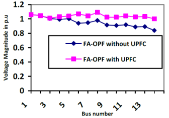
IEEE 14 bus system involves of five generator buses out of that first bus is considered as a swing bus and second, third, sixth and eighth buses are taken as generator buses & remaining all buses are PQ buses. All these buses are interconnected with twenty transmission lines. Simulations were done on MATLAB environment and the obtained results are presented in Tables. Table 1 indicates the input parameters of FA. Table 2 specifies the generator characteristics of IEEE 14 bus system. Table 3 specifies the UPFC parameters for different conditions. Table 4 designates various objectives in objective function consisting without and with UPFC using Firefly Algorithm. Table 5 presents the voltage profile comparison with GA & FA. Table 6 shows the optimized generator values of the generator using GA & FA. From these results, it is witnessed that FA is superior to GA. Figure 1 and Figure 2 presents the voltage magnitude and phase angles comparison with and without UPFC.
Figure 1. Comparison of bus voltages for 14bus system using FA-OPF without and with UPFC
Figure 2. Comparison of phase angles for 14 bus system using FA-OPF without and with UPFC
Table 1. Input parameters of Firefly Algorithm
|
S.No |
Parameters |
Quantity |
|
1 |
No.of. fireflies |
20 |
|
2 |
Maximum Generation |
50 |
|
3 |
Random movement factor (a) |
0.5 |
|
4 |
Attractiveness parameter (b) |
0.5 |
|
5 |
Absorption parameter (g) |
1 |
Table 2. Generator characteristics of IEEE 14 bus system
|
Generator Bus No |
a |
b |
c |
$P_{G}^{\min }$ |
$P_{G}^{\max }$ |
|
1 |
0.005 |
2.45 |
105 |
10 |
400 |
|
2 |
0.005 |
3.51 |
44.1 |
20 |
180 |
|
3 |
0.005 |
3.89 |
40.6 |
20 |
150 |
|
6 |
0.005 |
3.25 |
0 |
10 |
135 |
|
8 |
0.005 |
3 |
0 |
10 |
130 |
Table 3. Comparison of UPFC parameters in IEEE 14 bus system
|
|
location of UPFC (starting bus- ending bus) |
Parameters of UPFC |
|
|
Optimal Power Flow with GA |
13-14 |
Vcr |
0.04 |
|
θcr |
-87.1236 |
||
|
Vvr |
1.0183 |
||
|
θvr |
-14.6897 |
||
|
4-9 |
Vcr |
0.0440 |
|
|
θcr |
-87.1236 |
||
|
Vvr |
1.0191 |
||
|
θvr |
-8.1057 |
||
|
Optimal Power Flow With FA |
13-14 |
Vcr |
0.038 |
|
θcr |
-87.1236 |
||
|
Vvr |
1.02 |
||
|
θvr |
-4.6116 |
||
|
4-9 |
Vcr |
0.0394 |
|
|
θcr |
-87.1236 |
||
|
Vvr |
0.9975 |
||
|
θvr |
-2.8626 |
||
Table 4. Comparison of different objectives using FA -OPF in IEEE 14 bus system
|
IEEE 14 Bus System |
FA -OPF |
|
|
Parameter |
Without UPFC |
With UPFC |
|
Voltage deviation |
0.8940 |
0.5286 |
|
System loadability |
2.5967 |
2.3016 |
|
Active power losses |
4.8234 |
3.1207 |
|
Fuel cost |
1824.2853 |
1719.5398 |
|
Fitness function value |
549.4832 |
517.2688 |
Table 5. Comparison of voltage profile of IEEE 14 bus system
|
GA OPF & FAOPF |
No UPFC |
Non Optimal location of UPFC |
Optimal location of UPFC |
|
|
Genetic Algorithm based Optimal Power Flow |
UPFC connected between bus no’s |
----------- |
4-9 |
13-14 |
|
Net voltage deviation (p.u) |
0.9296 |
0.6106 |
0.5396 |
|
|
Firefly Algorithm based Optimal Power Flow |
UPFC connected between bus no’s |
----------- |
4-9 |
13-14 |
|
Net voltage deviation (p.u) |
0.8940 |
0.5637 |
0.5286 |
|
Table 6. Comparison of the real power generation of generator busses in various methods
|
PV bus N0 |
Generation limits |
GA-OPF |
FA-OPF |
|||
|
|
Min |
Max |
Without UPFC |
With UPFC |
Without UPFC |
With UPFC |
|
1 |
10 |
400 |
134.32 |
132.11 |
34.54 |
32.84 |
|
2 |
20 |
180 |
43.82 |
43.82 |
74.53 |
74.53 |
|
3 |
20 |
150 |
44.84 |
44.84 |
146.07 |
146.07 |
|
6 |
10 |
135 |
76.61 |
76.61 |
55.986 |
55.983 |
|
8 |
10 |
130 |
98.91 |
98.91 |
82.62 |
82.629 |
4.2 For 30 bus system
IEEE 30 bus system has six generator buses, in which first is slack bus and second, fifth, eighth, eleventh and thirteen buses are PV buses, remaining buses are PQ buses. These buses are connected by forty-one lines. Simulations are performed on MATLAB environment and the results have been tabulated. Table 7 represents the generator characteristics of 30 bus system. Table 8 shows the size of the UPFC for different conditions. Table 9 indicates various objectives of the minimization function. It shows the without and with UPFC objectives using Firefly Algorithm.
Table 7. Generator characteristics of IEEE 30 bus system
|
Generator Bus No |
a |
b |
c |
$P_{G}^{\min }$ |
$P_{G}^{\max }$ |
|
1 |
0.00375 |
2 |
0 |
50 |
300 |
|
2 |
0.0175 |
1.75 |
0 |
20 |
80 |
|
5 |
0.0625 |
1 |
0 |
15 |
50 |
|
8 |
0.00834 |
3.25 |
0 |
10 |
35 |
|
11 |
0.025 |
3 |
0 |
10 |
30 |
|
13 |
0.025 |
3 |
0 |
12 |
40 |
Table 8. Comparison of UPFC parameters in IEEE 30 bus system
|
OPF Methods |
location of UPFC (starting bus- ending bus) |
Parameters of UPFC |
|
|
Optimal Power Flow with GA |
21-22 |
Vcr |
0.1100 |
|
θcr |
-92.4571 |
||
|
Vvr |
1.0176 |
||
|
θvr |
-14.3387 |
||
|
Optimal Power Flow with FA |
21-22 |
Vcr |
0.0945 |
|
θcr |
-87.5156 |
||
|
Vvr |
1.0176 |
||
|
θvr |
-11.6496 |
||
Table 9. Comparison of different objectives using FA -OPF in IEEE 30 BUSSYSTEM
|
IEEE 30 bus system |
FA OPF |
|
|
Parameter |
Without - upfc |
With - upfc |
|
Voltage deviation |
0.9260 |
0.6589 |
|
System loadability |
3.4415 |
3.2376 |
|
Active power losses |
5.0034 |
4.4574 |
|
Fuel cost |
1002.4771 |
901.0301 |
|
Fitness function value |
302.7129 |
272.0536 |
Table 10. Comparison of Voltage deviation of IEEE 30 bus system
|
OPF Methods |
No UPFC |
Non Optimal location of UPFC |
Optimal location of UPFC |
|
|
Genetic Algorithm based Optimal Power Flow |
UPFC connected between bus no’s |
-------- |
25-26 |
21-22 |
|
Net voltage deviation (p.u) |
0.9361 |
0.722 |
0.6854 |
|
|
Firefly Algorithm based Optimal Power Flow |
UPFC connected between bus no’s |
-------- |
25-26 |
21-22 |
|
Net voltage deviation (p.u) |
0.9260 |
0.6911 |
0.6589 |
|
Table 11. Comparison of the Real power generation of Generator busses in various methods
|
PV bus NO |
Generation limits |
GA-OPF |
FA-OPF |
||||
|
|
Min |
Max |
Without UPFC |
With UPFC |
Without UPFC |
With UPFC |
|
|
1 |
50 |
300 |
173.82 |
173.24 |
86.95 |
86.41 |
|
|
2 |
20 |
80 |
49.104 |
49.1041 |
55.44 |
55.44 |
|
|
5 |
15 |
50 |
21.729 |
21.7296 |
44.58 |
44.58 |
|
|
8 |
10 |
35 |
23.854 |
23.8543 |
34.03 |
34.03 |
|
|
11 |
10 |
30 |
12.848 |
12.8483 |
28.42 |
28.42 |
|
|
13 |
12 |
40 |
12.009 |
12.0098 |
38.94 |
38.94 |
|
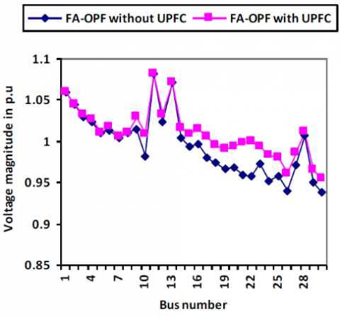
Figure 3. Voltage profile comparison for IEEE 30 bus system without and with UPFC
Table 10 presents the comparison of Voltage deviation considering FA & GA. Table 11 shows power generation of generator buses using GA & FA. From these tables, it is observed that FA is superior to GA. Figure 3 shows that after incorporating UPFC in FAOPF voltage, profile has been enhanced.
In this paper, a flock optimization method termed Firefly Algorithm applied to categorize the finest parameter tuning values of UPFC device. The effectiveness of Firefly Algorithm was proved and tested on two systems. Firefly Algorithm finds the best values for UPFC within a given limit by considering multi-objective function. The results indicate that after placing the UPFC in the IEEE14 bus & IEEE30 bus system, total transmission line losses are condensed, voltage profile boosted & loading capacity enlarged. The results attained with Firefly algorithm were accorded with genetic algorithm & it is witnessed that firefly algorithm superior to the genetic algorithm. Firefly algorithm will be implemented for optimization of real power generation and size of the multi type FACTS devices. Further to improve the system performance renewable energy sources will be incorporated in the power system.
[1] Pavella, K. (1997). Power system stability and control. IFAC Proceedings Volumes, 30(6): 63-75. https://doi.org/10.1016/S1474-6670(17)43347-7
[2] Bathina, V.R., Gundavarapu, V.N.K. (2014). Optimal location of thyristor-controlled series capacitor to enhance power transfer capability using firefly algorithm. Electric Power Components and Systems, 42(14): 1541-1553. https://doi.org/10.1080/15325008.2014.933371
[3] Hingorani, N.G., Gyugyi, L. (2000). Understanding FACTS: Concepts and Technology of Flexible AC Transmission System. Wiley-IEEE Press. https://doi.org/10.1109/MPER.2000.819913
[4] Acha, E., Fuerte-Esquivel, C.R., Ambriz-Perez, H., Angeles-Camacho, C. (2004). FACTS Modelling and Simulation in Power Networks, John Wiley & Sons Ltd, ISBN: 0-470-85271-2. https://doi.org/10.1002/0470020164
[5] Bakirtzis, A.G., Biskas, P.N., Zournas, C.E., Petridis, V. (2002). Optimal power flow by enhanced genetic algorithm. IEEE Transactions on Power Systems,17(2): 229-236. https://doi.org/10.1109/TPWRS.2002.1007886
[6] Basu, M. (2011). Multi-objective optimal power flow with FACTS devices. Energy Converse Manage, 52: 903-910. https://doi.org/10.1109/apcc.1999.825015
[7] Padiyar, K.R., Rao, U.K. (1999). Modeling and control of unified power flow controller for transient stability. Electrical Power and Energy Systems, 21(1): 1-11. https://doi.org/10.1016/S0142-0615(98)00028-3
[8] Yang, X.S. (2009). Firefly algorithms for multimodal optimization. Stochastic Algorithms: Foundation and Applications SAGA 2009, 5792: 169-178. https://doi.org/10.1007/978-3-642-04944-6_14
[9] Chowdary, D.D., Kumar, G.V.N. (2008). Restoration of single phase distribution system voltage under fault conditions with DVR using sliding mode control. Indian Journal of Science and Technology, 1(5): 1-5. https://doi.org/10.17485/ijst/2008/v1i5/29348.
[10] Kumar, S.B., Suryakalavathi, M., Kumar, G.V.N. (2016). Optimal location of thyristor controlled series capacitor to improve power system performance using line based composite index. Proceedings of 6th IEEE International Conference on Power Systems, 2016 (ICPS 2016), Indian Institute of Technology Delhi.
[11] Kumari, M.S., Maheswarapu, S. (2010). Enhanced genetic algorithm based computation technique for multi-objective optimal power flow solution. International Journal of Electrical Power & Energy Systems, 32(6): 736-742. https://doi.org/10.1002/cjce.20189
[12] Roa-Sepulveda, C., Pavez-Lazo, B. (2003). A solution to the optimal power flow using simulated annealing. International Journal of Electrical Power & Energy Systems, 25(1): 47-57. https://doi.org/10.1016/j.enpol.2007.09.033
[13] Sood, Y.R. (2007). Evolutionary programming based optimal power flow and its validation for deregulated power system analysis. International Journal of Electrical Power & Energy Systems, 29(1): 65-75. https://doi.org/10.1016/j.ijepes.2006.03.024 66
[14] Abido, M. (2002). Optimal power flow using particle swarm optimization. International Journal of Electrical Power & Energy Systems, 24(7): 563-571. https://doi.org/10.1007/s13369-012-0224-3
[15] Basu, M. (2008). Optimal power flow with FACTS devices using differential evolution. International Journal of Electrical Power & Energy Systems, 30(2): 150-156. https://doi.org/10.1016/j.ijepes.2007.06.011
[16] Mahdad, B., Srairi, K., Bouktir, T. (2010). Optimal power flow for large-scale power system with shunt FACTS using efficient parallel GA. International Journal of Electrical Power & Energy Systems, 32(5): 507-517.
[17] Rao, B.V., Kumar, G.N. (2014). Optimal location of thyristor controlled series capacitor for reduction of transmission line losses using BAT search algorithm. WSEAS Transactions on Power Systems, 9: 459-470. https://doi.org/10.1002/0470020164
[18] Yang, X.S. (2008). Nature-Inspired Meta-Heuristic Algorithms. Luniver Press, Beckington, UK. https://doi.org/10.1007/978-3-540-40046-2_7
[19] Rao, B.V., Kumar, G.V.N. (2015). A comparative study of BAT and firefly algorithms for optimal placement and sizing of static VAR compensator for enhancement of voltage stability. International Journal of Energy Optimization and Engineering (IJEOE), 4(1): 68-84. https://doi.org/10.4018/ijeoe.2015010105
[20] Rao, B.V., Kumar, G.V.N., Priya, M.R., Sobhan, P.V.S. (2009). Implementation of static VAR compensator for improvement of power system stability. Proceedings of International Conference on Advances in Computing, Control, and Telecommunication Technologies, ACT 2009 organized by ACEEE and CPS, Trivandrum, Kerala, India. 453-457.