M. Rupesh* | T S Vishwanath
© 2023 IIETA. This article is published by IIETA and is licensed under the CC BY 4.0 license (http://creativecommons.org/licenses/by/4.0/).
OPEN ACCESS
In present scenario, power demand is considered as the major problem, whereas the quality of the power has been diminished due to the nonlinear load conditions, which is harmful to the environment. Hence to improve the power quality in grid-connected photovoltaic system, this paper proposes a novel Empyreal Supervised Power Quality Framework. Initially, a novel MPPT technique has been introduced named as Sturdy and Forfeiture Tracking Point (SFTP) technique, which tackle the steady-state oscillations. Then the directed Squat PV system has been diminishing the loss in tracking direction. Finally, the power quality has been improved with the Puissance Redeem Circuit (PRC). The proposed framework has been simulated with Matlab Simulink and the results provides the improved power quality with the smallest total harmonic distortion of 1.51%.
power quality; Grid-connected PV system; MPPT technique; neural network; squat PV system; redeem circuit
In recent years, solar energy and other renewable energy have developed rapidly all over the world. The solar PV generation showed increased popularity in a rural area is mainly due to its easy installation, static nature, low maintenance, and zero fuel cost. For this purpose, the governmental and non-governmental organizations, show interest in supporting the installation of the rooftop PV system in rural areas for continuous electricity. The grid-connected form is one of the most gainful ways to exploit the PV energy, due to the requirements of modern civilization, the electrical energy demand is increasing at a high rate in global level. Recently, renewable, reliable, and environmentally friendly sources of energy have become one of the biggest challenges for scientists and engineers. According to them, PV applications need major attention in research field because they play a significant role in environmental problems in an efficient and effective manner. Attention should be given to improve the power quality by focusing on nonlinear loads and the limitations imposed by international standards such as IEEE519-1992 [13]. Such restrictions were designed to reduce disruptions and avoid major power system problems. Power Quality is also a service quality in broad sense, comprising supply efficiency, provided power quality, and knowledge provision. Most commonly used conservative interpretation in recent literature is the ability of power systems that controls loads without disrupting or harming a property primarily concerned with voltage efficiency at specific coupling points [27]. Unlike the term "reliability," which usually includes periods of minutes, typical power quality issues include shortterm events such as voltage drops or drops lasting from a few cycles to a few seconds caused by failures on nearby feeders, large loads switching on, etc., and sub-cycle transients triggered by switching power factor correction condensers, lightning strikes, etc. Power system harmonics and flicker issues often fall within the power efficiency category, mainly tend to occur at much longer intervals than those occurred at transients and sags.
The increasing demand for energy combined with the prospect of a reduced fossil fuels supply, as demonstrated by the petroleum crisis, in addition to the growing impacts associated with the environmental protection, has guided research and development of cleaner, sustainable alternative energy sources and have a little environmental impact [15]. Because of their independence from fossil and nuclear fuels and their low environmental impact, renewable energy sources are candidates for potential electricity. Photovoltaic (PV) sources are rapidly contributing to the generation of electricity worldwide. Among the alternative sources, electrical energy obtained from photovoltaic (PV) cells is currently considered to be a more valuable natural energy source, as it is safe, plentiful, renewable, and dispersed across the Planet, and is a primary factor in all other energy production processes on Earth [27].
However, given the phenomenon of atmospheric reflection and absorption of sunlight, it is estimated that the incidence of solar energy on the surface of the Earth is ten thousand times greater than the intake of energy in the world [19]. To avoid common problems in autonomous systems such as costly and bulky batteries requiring regular maintenance, the PV system must be run in grid-connected mode; this enables excess energy injection and demand coverage where supply is not sufficient [11]. The idea of a distributed generation of energy has become a real and present technological possibility in this context, encouraging numerous research works and standardizations in the world. Inspite of having advantages in energy generation through PV cells, the energy conversion performance is significantly low and the initial implementation cost is still considered high; thus, suitable techniques are required for the extraction of the maximum power from PV panels to achieve optimum operating efficiency [2]. PV panels show a special operating point at which PV power is maximized under uniform conditions of solar irradiation. The most important points of study of a grid-connected PV system are Maximum Power Point Tracking (MPPT). The PV system's main weakness is the high cost of installation and low efficiency. The operation of the PV system at its maximum power point is therefore important. There are a variety of MPPT algorithms (maximum power point tracking) suggested in the literature [8]. By constantly monitoring the maximum power point, MPPT is used to optimize the output from the PV array. Here the existing algorithms of the Maximum Power Point Tracker (MPPT) suffer from the downside of being slow or unreliable or both. MPPT's main principle is to draw the maximum available power from the PV module by making it run at an effective voltage (maximum power point) [5]. In other words, MPPT tests the PV module's performance by comparing it to the battery voltage and fixing the best power of the PV module for charging the battery and converting it to the best voltage for full battery power. A traditional solar panel can convert only 30 to 40 percent of solar irradiation incident into electricity [17].
A maximum power point tracking technique is used to improve the efficiency of the solar panel. There are different techniques used to track the maximum power point specific MPPT methods that were considered in PV systems such as Off-line techniques and on-line techniques can be categorized as the approaches [24]. The off-line techniques include a model of a PV array and temperature and solar irradiance calculation. Online techniques do not require temperature and solar irradiance calculation. However, they do not need the configuration of the PV series [22]. Some of the most sought after techniques are: Perturb and Observe (hill-climbing method) 2) Incremental Conductance method 3) Fractional short circuit current 4) Fractional open circuit voltage 5) Neural networks 6) Fuzzy logic etc [25]. Choosing the algorithm depends on the complexity of time the algorithm takes to track the MPP, the cost of implementation, and the ease of implementation. MPPT or Maximum Power Point Tracking is an algorithm that includes a load controller used to extract maximum available power from the PV module under certain conditions [18]. The capability of PV module generating maximum power at particular voltage is called maximum power point (or peak voltage). The maximum power varies according to ambient temperature, solar radiation, and temperature of the solar cell [1]. When a cell temperature of typical PV module measured at 25 ° C generates power with a maximum power voltage of about 17 V, can drop to about 15 V on a very hot day, and can also increase to 18 V on a very cold day. The PV module with a higher voltage output than the battery system operating voltage is utilized by the user with the help of MPPT solar charge controller [7]. From the above discussion, it is perceived that in previous many techniques followed to improve the power quality but still there is a lack of performance in some extents such as steady-state oscillation, loss of tracking direction, and control the unbalanced voltage. To tackle the above-mentioned issues, this paper proposes a novel Empyreal Supervised Power Quality Framework. The main contribution of the work is listed below,
A novel technique in MPPT is required for the extraction of maximum power produced at PV array, named as Sturdy and Forfeiture Tracking Point (SFTP) technique.
Under SFTP, Buoyant promulgation network has been tackling the steady-state oscillation. Similarly, directed squat PV system has been diminishing the loss of tracking direction.
Finally, a novel Puissance redeem circuit (PRC) has been introduced to improve the quality of power through balancing the unbalanced current and voltage.
The proposed framework has been implemented in Matlab Simulink tool, Simulation results are presented under linear and non-linear load condition, also the comparison analysis are presented.
Modi et al. [10] proposed a new control of a microgrid based on a three-phase solar PV-battery. This microgrid can transfer power smoothly when the operating system mode switches from grid-connected mode to standalone mode and vice versa. It provides the load with a continuous power even in the absence of grid and solar PV. In this state, the storage of battery energy works in the floating mode. Hence, the current of the battery goes from negative to zero.
Vivek Narayanan et al [12] introduce a stand-alone photovoltaic (PV) solar power storage (BES)-diesel generator (DG) powered microgrid network. The BES is directly incorporated into the voltage source converter (VSC) DC interface. This system works with maximum power extraction of the PV array along with improved power quality such as harmonic removal, reactive power compensation, and DG current balance. However, the maximum power of the PV array is effectively extracted from the MPPT controller by controlling the DC-DC converter.
Raut et al. [16] proposed an adaptive filter is included in this article. Because of the nonlinear loads, it eliminates the harmonics present in the current and makes it smooth sinusoidal to minimize total harmonic distortion (THD) according to IEEE-519. A boost converter interfaces VSC's PV and DC-links performs PV array maximum power point tracking (MPPT). Although, there are limitations on discrete-time signals and systems, so the independent time index k is a number. An adaptive filter model is selected with complexity considerations based on earlier awareness of the unknown device qualities.
Shubhra et al. [21] suggested the dynamic activity of the proposed system is improved by neural filter-based current controller, and the utility grid is provided with active power by using the variable atmospheric scenarios of the feed-forward term of solar PV power (FFTPV). A power electronics switch is used to adjust the VSC mode between the current control in the linked grid mode and the voltage control in an insulated mode to ensure continuous and sufficient power to the nonlinear load. However, by using the discrete PR controller in an isolated mode, the steady-state error between and sensed load voltages and the reference have been minimized and the load voltage THD is 3%.
Shan et al. [20] suggested a new microgrid control strategy to improve the quality of voltage. Droop control is widely implemented in current control techniques as a decentralized form of power-sharing at the expense of voltage deviations. Furthermore, traditional cascaded control with the relatively slow dynamic response is difficult to manage the fluctuation of renewable energy outputs, leads to further degradation of the voltage level.
Chauhan et al. [9] To minimize the possibility of losing tracking path in the solar photovoltaic device under variable irradiance, propose a Multiverse optimization (MVO) dependent MPPT controller. From the results, it is observed that the MVO-based MPPT controller is capable of avoiding drift and provides rapid convergence. Therefore, proposed controller outperforms in terms of tracking efficiency, setting time, peak overshoot, and integral absolute error. Since it does not occur better accuracy for tracking MPPT.
Patel et al. [14] presented a photovoltaic (PV) system control as distributed static compensator (DSTATCOM), termed as PVDSTATCOM, operated with two main components such as feed-forward control loop (FFCL) and active current control (ACC). The proposed PV system not only injects the active power into the utility grid, but also converts into a DSTATCOM on its own for providing some of the ancillary services such as source current harmonic suppression, load reactive current compensation, zero sequences component mitigation, and power factor adjustment. PV-DSTATCOM utilizes ACC to capture the basic in-phase and quadrature components of current. For reducing stationary faults produced in the PV inverter's current control loop, high-gain at the thirdorder harmonic is introduced by the PV-DSTATCOM. However, insolation shows frequent variations that leads to the undesirable voltage undershoot/overshoot and further increase ripple content in the DC-side capacitor voltage. This has a negative impact on the PV-harmonic DSTATCOM's attenuation capacity.
Goud et al. [6] developed the universal power quality conditioner (UPQC) with atom search optimization (ASO) to tackle the PQ problems in the HRES system. The work's major goal is to mitigate power quality (PQ) problems and compensate load demand in the HRES system. The UPQC device in the system is used to tackle the PQ issue concerns. To reduce current and voltage PQ problems, a fractional order proportional integral derivative (FOPID) with an ASO-based controller is used in series and a shunt active power filter is used to improve UPQC performance.
Thus from the above discussion, it is revealed that in [17] Hence, the current of the battery goes from negative to zero. [18] However, the maximum power of the PV array is effectively extracted from the MPPT controller by controlling the DC-DC converter. [19] There are limitations on discretetime signals and systems, so the independent time index k is a number. [20] However by using the discrete PR controller in an isolated mode, the steady-state error occurred between the reference and sensed load voltages have been minimized and the load voltage THD is 3%. [21] Furthermore, traditional cascaded control with the relatively slow dynamic response is difficult to manage the fluctuation of renewable energy outputs, leads to further degradation of the voltage level. [22] It does not occur better accuracy in tracking MPP. In [23], undesirable voltage undershoot/overshoot and increase in ripple content in the DC-side capacitor voltage are due to the frequent variations in insolation. This has a negative impact on the PV-harmonic DSTATCOM's attenuation capacity. Hence to tackle such issues there is a need to innovate a new strategy in the MPPT techniques to improve the power quality.
The rest of this article is as follows: In Section 2, covers the fundamental theories of the proposed approach. Section 3 describes a detailed case study analysis of the proposed approach. In Section 4, provides the simulation results; and finally, Section 5 gives the conclusions.
The solar photovoltaic grid-connected systems are presently commercialized due to ease of installation process and long module life. A major concern in PV generation is to address about the power quality. Tracking is required for enhancing the power quality, during the tracing, the maximum of the power deteriorates when changes in the operational environment circumstances such as solar irradiance and ambient temperature occurs. Every solar PV system uses a control algorithm, called MPPT algorithm for tracking the maximum power point (MPP). The purpose of the control options provided in micro grid systems under MPPT techniques, is to enhance the efficiency of the transmission system and maintain the quality of the electrical energy produced in terms of voltage and power factor. To overcome these problems, existing MPPT approaches follow the techniques to track extreme power that cannot be converged to the exact optimal operating point which is back and forth. Tracking direction loss is the major problem associated with MPPT algorithms, which occurs especially when there is a rapid change in irradiance. If the irradiance associated in this process shows further increase, then the function of the controller is to track the power and voltage for the current irradiation. This deviates from the real MPP to the operating value and the solar irradiance can fluctuate rapid in a cloudy situation, thus resulting in underperformance of MPPT and hampering the full PV array potential and continuously oscillates around the control set point which leads to Steady-state oscillation in both the voltage and power. Furthermore, the challenges affecting the power quality are unbalanced voltage, reactive power, harmonics, low power factor, voltage regulation, etc. In the solar-based micro grid, PV penetration could create an uncontrolled voltage phenomenon to the distribution system. It can be solved by considering a balanced distribution network in a three-phase system before PV installation. Also, conventional methods are unable to suppress uncontrolled voltage to permissible levels. The adverse impact of the uncontrolled voltage increases in output power ripples the PV inverter due to negative sequence voltage.
Figure 1. Empyreal supervised power quality
A novel Empyreal Supervised Power Quality for the PV system is proposed to improve the power quality, this framework introduces the new MPPT technique, Sturdy and Forfeiture of Tracking Point (SFTP) and the quality of power is improved by utilizing the Puissance Redeem circuit. Initially SFTP includes buoyant promulgation network, which efficiently tackled the Steady-state of voltage and power oscillation with accumulating multiple tested PV array at various irradiance and temperature levels for real-time observations of the operating environment in which the PV parameter collects the data and predicts the optimal operating points as per the condition and then follows the Squat PV System for diminishing the loss of tracking direction, then it determines the partial derivation of loss function for the direction changes based on weights. The output current produced in the PV array is promptly taken for designing the required algorithm. It efficiently tracks the exact direction even at the condition of further increase in irradiance by changing the operating point to the new actual MPP. The PV array depends the Puissance Redeem Circuit to effectively control the unbalanced voltage, which computes the reactance to allow single-phase load to change as a balanced three-phase load, as a final step taken for improving the power quality and thus the negative sequence components eliminated. Therefore, the proposed MPPT strategy is compared with Fuzzy logic, Perturb and observe, Incremental Conductance, and Ant colony optimization and also proposed Puissance Redeem circuit the power Quality technique is compared with Dynamic Voltage Restores, Unified power quality ConditionerDistributed Generation (UPQC-DG) and Distributed Energy Resource (DES). In this framework, it explores the MPPT technique of Sturdy and Forfeiture of Tracking Point.
3.1 Sturdy and Forfeiture of Tracking Point (SFTP)
Sturdy and Forfeiture of tracking point is a new MPPT technique in accordance with AI-based methods. Using Buoyant Promulgation network and Directed Squat PV system, this method effectively overcomes the issues in MPPT based on Steady State Oscillation and tracking Direction loss.
1) Steady-State Oscillation
The steady-state solution to the inhomogeneous differential equation of motion is specified and determined by the driving force and is independent of the initial conditions of motion. Mostly the modern MPPT approaches are entirely dependent on trial-and-error based and hence it needs some modifications using existing algorithms. Steady-state oscillations are produced in these approaches when the PV system hits the MPP. This problem can be understood by using a method to find the optimum point of PV array operation through hillclimbing approach. Let assumptions made that the array starts at point voltage and power measurements, Va and Pa respectively. The controller shifts the point of action from a to b, and measures Vb and Pb , If Pb> Pa and Vb> Va, then the controller shifts from a to b the operating point and performs the same procedures in order to locate the MPP. Finally, when it reaches the MPP, the controller interrupts the operating points to detect deflections in the system, such as irradiance fluctuations that leads to frequent oscillations in the power and voltage. Along with, MPPT technique the loss of tracking direction problem is defined below.
2) Loss of Tracking Direction
One more issue connected with traditional trial and error based MPPT algorithm is loss of tracking direction, especially occurs when there is rapid change in irradiance and multiple PV curves are plotted based on levels of irradiance. Operational voltage from Va to Vb is altered by the MPPT controller while the solar irradiation increases from 100 W/ m2 to 200 W/m2, the controller estimates the power as Pb> Pa. This shows significant movement of the point of action from a to b. if the irradiance continues to increase in this phase, the controller will repeat the procedure and diverge the operating point from the actual MPP. In an overcast scenario, solar irradiance can fluctuate rapidly and resulting MPPT to underperform and impeding the PV array’s potential. System modeling of SFTP technique is given below,
Figure 2. Sturdy and forfeiture of tracking point
Fig. 2 exemplifies a typical grid-connected PV system configuration comprising of a PV array, a transformer, a DC / DC converter, and a DC / AC source converter (VSC). The DC / DC converter controller is provided with an algorithm. Realtime measurements of the operating environment (i.e. irradiance and temperature) and PV parameters are fed into the network, that is arranged to collect the data and predict the optimal operating points (MPP reference) for the present situation. The process to overcome steady-state oscillation and loss of tracking direction is explained below in detail.
3.1.1 Buoyant Promulgation Network (BPN) & Directed Squat PV System (DSPS)
Buoyant Promulgation Network (BPN) which is meant to effectively tackle the steady-state oscillation in voltage and power with the help of multiple tested PV arrays, at various irradiance and temperature levels for real-time operating environment measurements in which the PV parameter collects the data and predicts optimal points of action for the present situation.
Directed Squat PV System (DSPS) to reduce the loss of tracking path, it calculates the partial loss function derivation for weight direction changes. The produced output current of the PV array can promptly use in our algorithm design. It tracks the exact direction efficiently, by changing the operating point to the new actual MPP when there is a continuous increase in irradiance.
The proposed SFTP comprises a four-layer NN with one input and output layer, and two hidden layers and each layer is provided with 20 neurons. The back-propagation algorithm calculates the gradient for updating NN's weights. Different curves showing PV characteristic of the PV array can be obtained at various irradiance and temperature rates via quantitative offline simulations. The mathematically found vertices values corresponding to the MPPs in different operating environments is found. Both data sets are then added to the NN as training samples by considering two inputs (i.e., irradiance and temperature) and one output (i.e., MPP reference) into account.
The ‘Buoyant Promulgation Network’ finds the minimum point of the loss function with an adaptive learning rate.
This neural network calculation process is classified into forward propagation processing and backward propagation processing. During the forward propagation processing, the NN propagates layer by layer using (1) to get the output y,
$\left\{\begin{array}{l}z^l=w^l \bullet f_l\left(z^{l-1}\right)+b^l \\ y=f_l\left(z^l\right)\end{array}\right.$ (1)
where, $z^l, w^l, f_l(\bullet)$ and $b^l$ are the inputs, weights matrix, activation function for neurons of the layer $l, b^l$ represents bias from layer $l-1$ to layer $l$, respectively. Accordingly, the square error E can be calculated by
$E=\sum \frac{1}{2}\left(y^*-y\right)^2$ (2)
where, y* is the expected output; Then the BPN enters the backpropagation process by updation of weights w and bias b from output Layer to input layer following the direction of gradient descent. The updating laws can be defined as
$w_{t+1}=w_t-\mu \frac{\partial E}{\partial_{w_t}}$ (3)
$b_{t+1}=b_t-\mu \frac{\partial E}{\partial_{b_t}}$ (4)
where, $\mu$ is the learning rate of weight $w_{t+1}$ and bias $b_{t+1}$ are updated weight and bias respectively. After determining the weight and bias for the steady-state oscillation, it needs to find the tracking direction to obtain maximum power.
Instead of determining the changing quantity of the weight, the partial derivation of loss function determines the change in direction on weights. If the signs of the gradient of the loss function are different at the time point t-l and t, which indicates it has crossed the minimum point of the function, the learning rate P should multiply a constant Pdown. On the contrary, if the symbols are the same, namely it has not reached the minimum point $\mu$ and can multiply a constant $(\mu \mathrm{up}>\mathrm{z})$. Comparing to the traditional algorithms, it shows a faster convergence speed, and there is no need to set parameters in advance so that it avoids the difficulty of setting an exact optimal learning rate.
The corresponding updating algorithm can be mathematically expressed as
$\mu(t)=\left\{\begin{array}{l}\mu^{u p} \mu_{t-1}, \forall g(t-1) g(t)>0 \\ \mu^{d o w n} \mu_{t-1}, \forall g(t-1) g(t)>0 \\ \mu, \quad \text { otherwise }\end{array}\right.$ (5)
where, g(t) is the error function gradient at time t. The detailed implementation process of the proposed system is as below:
Implementation of Neural Network
|
1. Normalize input value G, T 2. for neuron 1 to j from layer l, calculate the output using (1) calculate the square error E using (2) 3. if $\mathrm{E}>\varepsilon$ update weight w and bias b using adaptive learning rate based on (3) to (5) 4. else output (zl) 5. end |
The pre-trained Sturdy and Forfeiture of Tracking Point module is arranged to gather required data and predict a corresponding maximum power reference, whenever there is a change in the irradiance or temperature. Now the DC / DC converter is effectively controlled using a classic proportionalintegral (PI) method allowing PV arrays to track the updated maximum power reference. The main duty of the external grid is to control the voltage of the DC-link via a VSC.
The proposed method utilizing SFTP is capable of predicting and tracking the MPP in real-time without considering significant changes in temperature and irradiance, thus reaching the maximum power and enhancing the internal series resistance and hence eliminating the common drawbacks of conventional MPPT approaches. SFTP reference is greater than the actual power when there is an occurrence of pseudo short circuit (i.e the system is unable to reach and track the given reference), and the output current of the PV array will move to its short-circuit current. The PV array’s output is subsequently used as an event trigger mainly for designing the algorithm for the Direct Squat PV system.
Once actual maximum power reaches the current will come back to the normal value, in other words, top to bottom approach is used in the proposed method to find the actual MPP. But in traditional MPPT-based trial-and-error algorithms bottom to top approach is followed to test the MPP, thus leading to a local rather than a regional MPP. From this, conclusion can be made that the proposed Direct Squat PV system has ability to find the exact global MPP because it examines the maximum possible points through top to bottom approach. Thus the maximum power is tracked with the steadystate oscillation with exact direction. However, when the power passes through the microgrid may cause the voltage to unbalance the issue, to control this unbalanced voltage Puissance Redeem Circuit is introduced.
3.2 Puissance redeem circuit
Puissance Redeem Circuit controls the unbalanced voltage to convert a single phase load into a balanced three-phase load by computing the reactance. The circuit is said to be balanced only when the negative sequence components are eliminated and proper control over the unbalanced voltage is obtained. Here Puissance Redeem Circuit is applied mainly to the distributed PV systems. Puissance Redeem Circuit is specifically designed to compute the reactive power injections required by distributed PV systems to achieve balance in the voltage. Whenever voltage unbalances occur it can be improved by the effective control of active and reactive power injections, only considering the reactive power control since assuming the owners of the PV systems would like to maximize the active power output of their devices.
The voltage unbalance factor (VUF) is given by [25],
$V U F \%=\frac{negative \, sequence \, voltage}{positive \, sequence \, voltage} \times 100$ (6)
Puissance Redeem Circuit pushes the derive circuit design to zero and the equations for constant impedance loads under controllable reaction assuming unbalanced supply voltages is driven and assume that the compensators are at controllable reaction and resistance. Assumptions are made while doing comparison are balanced supply voltages and compensation is given by constant loads, i.e. solar PV inverters, by injecting only the reactive power. Deriving the compensating reactions at initial stage is required to balance a constant impedance load of a single-phase and the reactive power injections to balance a constant power load of a single phase. For further balancing unbalanced condition, a constant three-phase impedance and constant power equation is derived.
3.2.1 Single-phase load
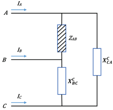
Single-phase loads controlled by a generating set of three phases must be distributed so that, no more than the generator’s rated current runs at each phase. Puissance Redeem circuit provided for a single-phase load ZAB connected between phase A and phase B is given below,
Figure 3. Puissance Redeem circuit provided for a singlephase load ZAB connected between phase A and phase B
Figure 3 shows a Puissance Redeem Circuit provided for a single-phase load. Assume that the load, connected between phases A and B, is designed as a constant impedance load $Z_{A B}=R_{A B}+j X_{A B}$ (its admittance is $Y_{A B}=G_{A B}-j B_{A B}$). Puissance circuit design allows computing the reactance connecting to phases BC and CA to convert the single-phase load into a balanced three-phase load. The circuit shows balanced effect only when the negative sequence components are eliminated. The susceptances that should be connected ($B_{B C}^c=1 / X_{B C}^c, B_{C A}^c=1 / X_{C A}^c$) are computed mainly as follows.
According to Kirchhoff’s current law:
$\left[\begin{array}{l}I_A \\ I_B \\ I_C\end{array}\right]=\left[\begin{array}{ccc}1 & 0 & -1 \\ -1 & 1 & 0 \\ 0 & -1 & 1\end{array}\right]\left[\begin{array}{l}I_{A B} \\ I_{B C} \\ I_{C A}\end{array}\right]$ (7)
The Symmetrical components present in the line components are obtained with the Fortescue transformation [26]:
$\left[\begin{array}{l}I_0 \\ I_{+} \\ I_{-}\end{array}\right]=\left[\begin{array}{ccc}1 & 1 & 1 \\ 1 & a^2 & a \\ 1 & a & a^2\end{array}\right]\left[\begin{array}{l}I_A \\ I_B \\ I_C\end{array}\right]$, (8)
Where $a=e^{j 2 \pi / 3}$ and $I_0, I_{+}, I_{-}$ are the zero, positive, and negative sequences of current, respectively. When the circuit is balanced, the negative sequence current shows the value of zero:
$3 I_{-}=\left(1-a^2\right) I_{A B}+\left(a^2-a\right) I_{B C}+(a-1) I_{C A}=0$ (9)
We know $I=V Y$, it takes the value $I_{A B}, I_{B C}, I_{C A}$ with their corresponding voltage and admittance:
$\left(1-a^2\right) V_{A B} Y_{A B}-\left(a^2-a\right) V_{B C}\left(j B_{B C}^c\right)-(a-1) V_{C A}\left(j B_{C A}^c\right)=0$ (10)
When the circuit is balanced, $V_{B C}=a^2 V_{A B}, V_{C A}=a V_{A B}$. Divide (10) with $V_{A B}$ and split it to get its real and imaginary parts:
$-\frac{3}{2} B_{A B}+\frac{\sqrt{3}}{2} G_{A B}+\frac{3}{2} B_{B C}^c=0$, (11a)
$-\frac{\sqrt{3}}{2} B_{A B}+\frac{3}{2} G_{A B}+\frac{\sqrt{3}}{2} B_{B C}^c-\sqrt{3} B_{C A}^c=0$, (11b)
Therefore, the susceptances are:
$B_{B C}^c=-\frac{G_{A B}}{\sqrt{3}}+B_{A B}, \quad B_{C A}^c=\frac{G_{A B}}{\sqrt{3}}+B_{A B}$ (12)
The process to determine the suspectances is same for all phases of loads. When the load is designed as constant power $S_{A B}=P_{A B}+j Q_{A B}$, we replace $I_{A B}, I_{B C}, I_{C A}$ in (9) with their corresponding power and voltage and derive the compensating reactive power injections using the same process, then derive the unbalance three-phase load.
3.2.2 Unbalanced three-phase load
An unbalanced three-phase circuit comprises at least one source or load which is not symmetrical with three phases. Similarly, a three-phase load with different impedance values for the phase will unbalance a circuit. Complete compensation of an unbalanced three-phase constant impedance load can be obtained as follows
$\begin{aligned} B_{A B}^c=\frac{G_{B C}}{\sqrt{3}}+B_{B C}-\frac{G_{C A}}{\sqrt{3}}+B_{C A}, \\ B_{B C}^c=\frac{G_{C A}}{\sqrt{3}}+B_{C A}-\frac{G_{A B}}{\sqrt{3}}+B_{A B}, \\ B_{C A}^c=\frac{G_{A B}}{\sqrt{3}}+B_{A B}-\frac{G_{B C}}{\sqrt{3}}+B_{B C},\end{aligned}$ (13)
And unbalanced three-phase constant power load equations are as follows:
$\begin{gathered}Q_{A B}^c=\frac{P_{B C}}{\sqrt{3}}+Q_{B C}-\frac{P_{C A}}{\sqrt{3}}+Q_{C A}, \\ Q_{B C}^c=\frac{P_{C A}}{\sqrt{3}}+Q_{C A}-\frac{P_{A B}}{\sqrt{3}}+Q_{A B}, \\ Q_{C A}^c=\frac{P_{A B}}{\sqrt{3}}+Q_{A B}-\frac{P_{B C}}{\sqrt{3}}+Q_{B V},\end{gathered}$ (14)
After converting the single-phase load into a three-phase load we can explore the Puissance Redeem Circuit along with buses.
3.2.3 Exploration of puissance redeem circuit
In this section exploration of the Puissance Redeem Circuit with 5 busses radial distribution system is connected with a balanced, unbalanced three-phase load to balance the voltage by assuming compensator reactance or reactive power injections.
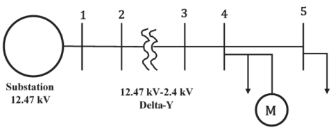
Figure 4. One-line diagram of a 5-bus distribution system
The above diagram Figure 4, represents five bus radial distribution system along with the number of studies made in it. The voltage source is perfectly balanced (12.47 kV line-toline) and a delta grounded wye transformer is connected between buses 2 and 3 are the assumption made. All line segments are balanced, unbalanced three-phase deltaconnected loads are connected to busses 4 and 5 and a threephase compensator is connected to bus 4 or 5. It balances bus 4 by assuming some equipment that is sensitive to voltage unbalance, such as a three-phase motor, is connected to the bus however it does not represent voltage regulators. Additional assumptions are that the compensator reactance or reactive power injections are unconstrained. The reactive power capabilities of a PV inverter would create limitation by taking the size of inverter and active power injections into account. Thus it balances the voltage through three-phase controllable reactance, reactive power, and with the impedance load and power, the load is explained below.
3.2.3.1 Compensator with three-phase controllable reactance: Constant impedance load
The equations for balancing unbalanced constant threephase impedance and constant power loads. First, shows the application of the Puissance Redeem circuit to balance the voltage at bus 4 when we control the reactance (Xc).
Case 1: Compensator at bus 4
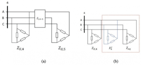
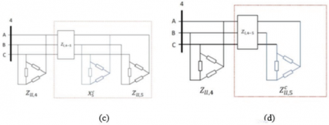
Computation of the equivalent impedance of the downstream circuit Zeq can be obtained by using the delta-wye transformation when the controllable reactance is connected to bus 4, and then the total unbalanced load at bus 4 and complete balance of the voltage at bus 4 can be obtained.
Case 2: Compensation at Bus 5
When the bus 5 receives the connection of controllable reactance, as shown in Figure 5c, the achievement of computation $X_5^c$ can be as follows. Also, get the equivalent impedance of the load in the red box according to case 1 in Figure 5b. Utilize the impedance load to compute the impedance $Z_{u, 5}^c$ as shown in Figure 5d. The compensation at bus 5 which balances the voltage at bus 4, is obtained through the difference between $Z_{u, 5}^c$ and $Z_{u, 5}$. However, obtained difference may not be pure reactance so complete elimination of the voltage unbalances at bus 4 is difficult because the compensator is unable to provide resistance.
Figure 5. Three-phase system for bus 4. (a) the base case. (b) Balancing equipment at bus 4. (c) Balancing equipment at bus 5(d) Equivalent circuit to (b) needed to compute $X_5^c$
3.2.3.2 Compensator with three-phase controllable reactive power: Constant impedance Load
To balance the voltage at bus 4 assuming constant impedance loads, three-phase PV inverter is used. The compensating reactance’s computed initially are used together with measurements of the line voltages to get the reactive power injections
Case 3: In this case, the compensator present at bus 4 using $X_4^c$ from case 1 and the measured voltage at bus 4.
Case 4: In this case, the compensator present at bus 5 using In this case, the compensator present at bus 5 using $X_5^c$ from case 2 and the measured voltages at bus 5,
In the above cases, the Puissance Redeem circuit shows failure of voltage balance at bus 4. This is mainly due to the effort of change in measured voltage after injecting the reactive power.
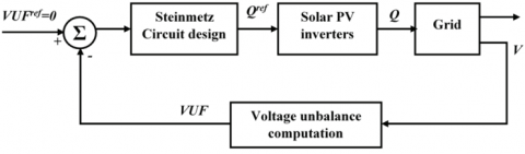
Figure 6. Feedback control diagram
A simple feedback control strategy as shown in figure 6, is developed to drive the unbalance towards zero by setting reference VUF to zero. Voltage is measured at the bus. If the VUF is not zero, application of the Puissance Redeem circuit tp is necessary to determine the required reactive power injections, that are used by the PV inverters as references, where the PV inverters are exactly designed to provide what is requested. However, in practical application they become more saturated.
Case 5: Compensator at bus 4, Feedback control.
When the PV system is placed on bus 4, it notifies the voltage unbalances at bus 4 and is completely eliminated by using feedback control mechanism.
Case 6: Compensator at bus 5, Feedback control
When the PV system is placed on bus 5, the PV inverters cannot completely balance the voltage as in case 2 because it only injects reactive power and not the active power.
3.2.3.3 Compensator with three-phase controllable reactive power: Constant Power Load
Next, we use a three-phase PV inverter to balance the voltage at bus 4 based on the assumption of constant power loads at bus 4. We measure the line-to-line voltage at bus 4 and the line currents which is further converted into equivalent delta-load current by using the transformation. Then, computation of the power demand of downstream loads and network losses can be done, and repeat the procedure for the other phases. The total power demand at bus 4 is obtained by the addition of suitable load on bus 4. Finally, the computation of the compensating reactive power injections can be done.
Case 7: Compensator on bus 4.
Puissance Redeem circuit shows failure to balance the voltage at bus 4 because change in network losses occurs when the reactive power is injected. Case 9 proves that the unbalance can be eliminated using feedback control.
Case 8: Compensator on bus 5.
Here the loads are designed as constant power loads, the procedure we used in Case 2 for computing the equivalent impedance that fails to work. But here, it simply applies the compensating reactive power injections computed in case 7 to bus 5 rather than bus 4, to effectively neglect the impact of the line impedance.
Case 9: Compensator at bus 4, feedback control.
Since cases 7 and 8 shows that the failure of Puissance Redeem circuit to achieve balance for constant power loads, and hence repeat use of the feedback control strategy. Like as before, feedback control completely eliminates unbalances at bus 4. It gives incremental difference in values obtained in case 7.
Case 10: Compensator at bus 5, feedback control.
If the PV system is located on bus 5 complete elimination of the unbalance occurred on bus 4.
Case 11: Compensator at bus 5, feedback control (load model mismatch).
Difficulty in driving VUF to zero occurred in case 6. So apply the case 10 strategy to case 6. Instead of computing the compensating reactive power assume that the loads are constant power loads (here the loads are implemented as constant impedance loads).
Puissance Redeem circuit perfectly balances the voltage at the bus when the compensator is connected to loads that are designed as constant impedance loads. Here it shows significant improve in balance in all cases. The use of the Puissance Redeem circuit within a feedback controller can show contrast achievement in perfect balance in all cases in which the controller with constant power loads is assumed. Thus the overall Empyreal Supervised Power Quality Framework efficiently overcomes steady-state oscillation, loss of tracking direction, and unbalanced voltage over and done with the well-organized techniques.
The proposed methodology is implemented in MATLAB Simulink and the simulation results are discussed below. The proposed technique is described in previous section 3 and in this section the detail explanation and its performance is analyzed.
Platform: MATLAB Simulink
OS: Windows 10
Processor: Intel core i5
RAM: 8 GB RAM
4.1 Simulation outputs
Empyreal Supervised Power Quality Framework for Tracking maximum power and improve power Quality simulation outputs are shown below figures and also the simulated representation of each parameter in the simulation has been deliberated following,
Table 1. Experimental parameters
|
Parameters |
Value |
|
Grid Frequency |
50 Hz |
|
Maximum Power of PV |
244 (W) |
|
Open circuit Voltage |
50.8 (V) |
|
Voltage at maximum power point |
42.8(V) |
|
Diode saturation current |
1.29E-12 |
Figure 7. Overall simulink design
Figure 7 states the overall Simulink design of the proposed Empyreal Supervised Power Quality Framework. The controller which placed in the simulated design is shown briefly in fig 9. It depicts the overall design of framework which includes Sturdy and Forfeiture Tracking Point.
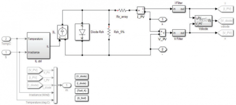
Figure 8. PV model design
Fig 8 illustrate the PV model design of the proposed Empyreal Supervised Power Quality Framework. The PV model design has the PV array module i.e., SFTP which is connected to the grid where power and current are provided in PV model which converts the DC current to AC current to efficiently produce good power quality. SFTP predicts and tracks the MPP in real-time irrespective of considerable changes in irradiance and temperature.
Figure 9. Complete diagram
Figure 9 states the Complete Diagram of the proposed Empyreal Supervised Power Quality Framework. It depicts the overall design of framework which includes Sturdy and Forfeiture Tracking Point.
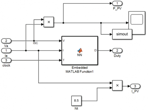
Figure 10. MPPT design
Figure 10 states the MPPT Design of the proposed Empyreal Supervised Power Quality Framework. It depicts the overall design of framework which includes Sturdy and Forfeiture Tracking Point.
Figure 11. Peak point detection
Figure 11 represents the initial stage of peak point detection while simulation the power reaches the particular peak as shown. The detected peak point is 184-watt power for 32 volts without proposed controller.
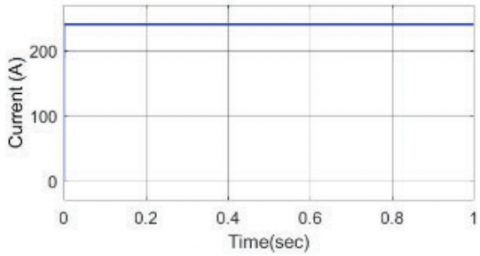
Figure 12. PV current after the process of sturdy and Forfeiture of the tracking point
Figure 12 shows the PV current after the process of steadystate oscillation and tracking the direction to obtain the maximum power from the PV modules. Therefore, it efficiently precedes the steady-state oscillation of current and also tracking at accurate direction by the Sturdy and Forfeiture Tracking Point.
Figure 13. PV Voltage after the Process of Sturdy and Forfeiture of the Tracking point
Figure 13 represents in the initial stage of PV design, while providing the power supply it reaches the maximum power from the PV module. Then, after proceeding with the process of steady- state oscillation and tracking point, SFTP regulates the voltage as a result it effectively precedes the steady state oscillation of 230 v.
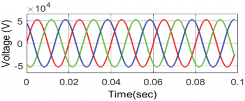
Figure 14. Current under unbalanced condition
Figure 14 states the unbalanced condition in current during the power generation from MPP to the microgrid. The MPPT tracks maximum current and voltage from the PV array, then it converts the DC current into the AC current through the DC/AC converter. Whereas, the output of the DC/AC converter is in the form of unbalanced AC current. The threephase current under unbalanced condition has been depicted in figure 14.
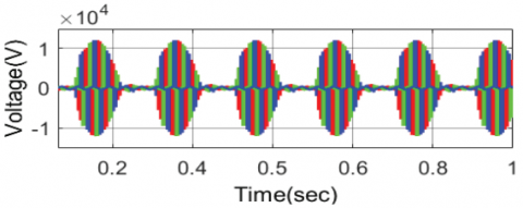
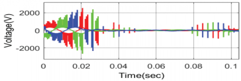
Figure 15. Voltage under unbalanced condition
Similar to the current, the three-phase voltage under the unbalanced condition has been presented in figure 15. The obtained unbalanced voltage has to be balanced, which can be done by the proposed method.
Figure 16 states that the reactive power loads for unbalanced voltage during the power transaction through a microgrid. Reactive Power at load for each second in time-varying with the power (W) the unbalanced condition is noted. Constantly the offset value is set to zero during the transaction of power in the reactive power load to measure the unbalance condition.
Figure 16. Reactive power at load for unbalanced condition
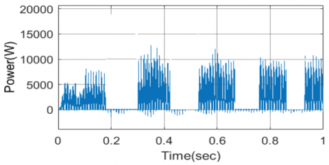
Figure 17. Real power at load for unbalanced condition
Figure 17 states that the active power loads for unbalanced voltage during the power transaction through a microgrid. Real Power at load for each second in time-varying with the power (W) the unbalanced condition is noted. Constantly the offset value is set to zero during the transaction of power in the reactive power load to measure the unbalance condition.
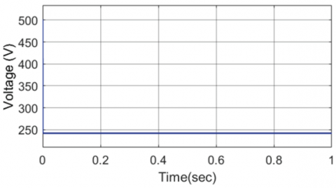
Figure 18. Voltage at micro grid
Figure 18 states the final voltage at Microgrid after control the unbalanced voltage. Significant balancing of unbalanced constant three-phase impedance and constant power loads is often required for perfect balancing of voltage varying with time per second. The effect of step-up transformer provides the voltage at microgrid as 50kV. The offset value is constantly set as 0.9. This balanced voltage improves the power quality in solar-based microgrids.
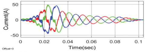
Figure 19. Current at the microgrid
Figure 19 states the final current at Microgrid after control the unbalanced voltage. The graph shown that, the current quality is not good after 0.06 sec, where some variations has been presented in the current waveforms. This needs to be balanced to improve the power quality, which can be done by the proposed puissance redeem circuit. The offset value is constantly set as 0.9.
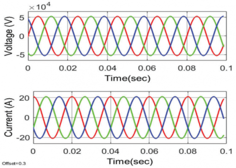
Figure 20. Power quality with linear load
Figure 20 states the Power quality with linear load under the proposed Empyreal Supervised Power Quality Framework. From the graph, the quality of the current and voltage has been improved under the linear load condition.
Figure 21. Power quality issue without linear load
Figure 21 states the Power Quality issue without Linear load. The graph shown that, the three-phase current without the linear load has were not in the balanced manner. Compared the quality of power with linear load is better than the quality without linear load.
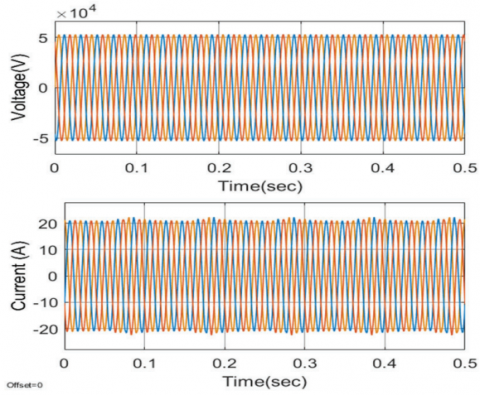
Figure 22. Power Quality with non-linear load condition
Figure 22 represents the power quality with non-linear load condition and shows that the power quality is improved by originating of temperature and instance vs current and voltage and also it reduces the distortion while simulating the 3 phase current and voltage under non-linear load condition.
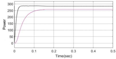
Figure 23. Power quality without peak point variation
Fig 23 represents the comparison graph of existing system in pink color as well as the proposed system without peak point variation in black color. The power quality has been improved by the proposed puissance redeem circuit with 280 w.
Figure 24. Power quality Issue with peak point variation
Figure 24 states the Power Quality Issue without Puissance Redeem Circuit of proposed Framework. Different from the graph depicted in figure 23, this exhibit the similarity among the curves, which represents the improved power quality through the proposed puissance redeem circuit.
Figure 25 and figure 26 states the Overall FFT Fundamental analysis for total harmonic distortion (THD) at before and after using the proposed Empyreal Supervised Power Quality Framework respectively where FFT window is represented by the red color which has 5 cycles and the blue color is the selected signal of in one cycle. In which, the total harmonic distortion has been reduced with the fundamental value from 24.87% to 1.51%. The proposed framework obtains the lowest THD value as 1.51%.
4.2 Comparison analysis
Overall Comparison Analysis for the proposed method includes two techniques such as Sturdy and Forfeiture Tracking Point and Puissance Redeem Circuit. The existing system for the following approaches are Perturb and Observe (P&O), Incremental Conductance (IC), Fuzzy logic, Ant Colony Optimization (ACO), Dynamic Voltage Restoration (DVR), Unified Power Quality Conditioner- Distributed Generation and Distributed Energy Resources (DER).
Figure 25. FFT analysis of THD, before using proposed work
Figure 26. FFT analysis of THD, after using proposed work
4.2.1 For sturdy and forfeiture tracking point
The overall comparison of the proposed system with an existing system is evaluated by considering the following approaches that are taken into an account such as Perturb and Observe (P&O), Incremental Conductance (IC), Fuzzy logic, Ant Colony Optimization (ACO).
Figure 27. Comparison of Various MPPT techniques in different color representation
Figure 27 shows the comparison of exiting models such as Perturb and Observe (P&O) in red color, Incremental Conductance (IC) in yellow color, Fuzzy logic in purple color, Ant Colony Optimization (ACO) in green color with the proposed Empyreal Supervised Power Quality Framework in blue color. From the figure, it is noted that range of the voltage is compared with time in seconds in the range of 0 to $10 \times 10^5$. While comparing the voltage of the proposed method with other existing models, the proposed method achieves the range of 0V to 240V. Here the existing models such as ACO and Fuzzy achieves the range of 0V to 210V. Moreover, IC achieves the range of 0V to 230V and P&O achieves the range of 0V to 235V. It depicts that sturdy and Forfeiture Tracking Point has better performance when compared to the existing methods.
4.2.2 For puissance redeem circuit
The existing system for Voltage unbalance, the following approaches are taken into an account such as Dynamic Voltage Restoration (DVR), Unified Power Quality ConditionerDistributed Generation, Distributed Energy Resources (DER).
Figure 28. Dynamic Voltage Restoration (DVR)
Figure 28 states the performance of unbalanced voltage in the Dynamic Voltage Restoration (DVR) method. This method compares with the proposed method show that the Puissance Redeem Circuit shows better performance than the dynamic Voltage Restoration technique.
Figure 29. Unified power quality conditioner- distributed generation
Figure 29 states the performance of unbalanced voltage in the Unified Power Quality Conditioner- Distributed Generation technique. In Wang G et al [Wang, Gongke, et al (2020)], the electric load might be linear or non-linear that affects the quality of the power of the system. Harmonics are in the form of frequency which is the function of the waveform as a resultant, the distortion is created. Total Harmonic Distortion(THD) is the sum of multiple harmonic in the system, because THD on the power distribution network is one of the concern in power quality so it is required to evaluate the distortion in the system by using the below term:
$T H D=\sqrt{\frac{V_2+V_3+V_4 \cdots}{V_1}}$
The total sum of all harmonics of either voltage or current waveform divided by the component of voltage or current where V denotes the voltage.
This method compares with the proposed method show that the Puissance Redeem Circuit shows better performance than the Unified Power Quality Conditioner- Distributed Generation technique.
Figure 30. Distributed Energy Resources (DER)
Figure 30 states the performance of unbalanced voltage in Distributed Energy Resources (DER). This method compares with the proposed method show that the Puissance Redeem Circuit shows better performance than the Distributed Energy Resources technique.
Thus the above result shows that Power Quality performance for solar-based microgrids obtained from the proposed network achieves better performance. Eventually, the comparison results reveal that the suggested power quality Approach performs well compared to existing Approaches. Therefore, the power quality for PV microgrids is enhanced in our proposed work while controlling the unbalanced voltage along with the new MPPT Technique.
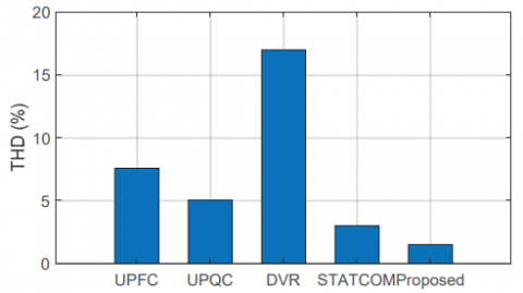
Figure 31. Comparison of total Harmonic distortion
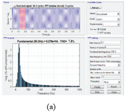
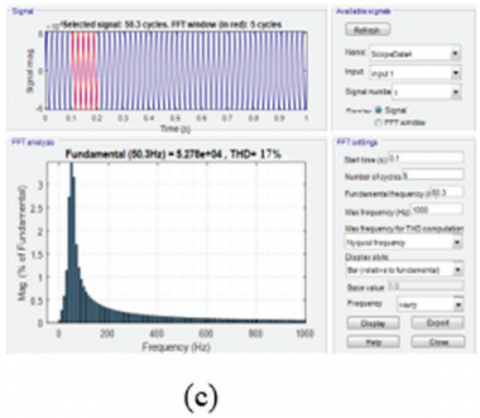
Figure 31 states THD Analysis and comparison with other methods like Unified power flow controller (UPFC), Unified power quality conditioner (UPQC), Dynamic voltage restorer (DVR), and Static synchronous compensator (STATCOM). From the graph, it is clear that, the THD of the proposed framework is as much smaller than the other existing techniques. Also the FFT analysis of total harmonic distortion of the compared techniques are presented in figure 32. Figure 32 (a) states THD of UPFC as 7.2%, figure 32 (b) states THD of UPQC as 5%, figure 32 (c) states THD of DVR as 17%, figure 32 (d) states THD of STATCOM as 2.99%, and figure 26 states THD of proposed work as 1.51%.
Table 2. Comparison of total harmonic distortion
|
Techniques |
THD (%) |
|
UPFC |
7.8 |
|
UPQC |
5 |
|
DVR |
17 |
|
STATCOM |
2.99 |
|
Proposed |
1.51 |
Figure 32. FFT analysis of Total Harmonic Distortion (a) UPFC (b) UPQC (c) DVR (d) STATCOM
PV applications received much research attention due to their capability of addressing environmental issue in an efficient and effective manner. PV-based microgrids with high-efficiency require number of maximum power point tracking (MPPT) controllers to maximize the energy harvested due to the nonlinearity in the PV modules characteristics. For this power quality improvement, the Empyreal Supervised Power Quality Framework highly overcomes the issues of steady-state oscillation with the buoyant promulgation network and loss of tracking direction by Directed Squat PV System. Moreover, the suggested Puissance Redeem circuit controls the unbalanced voltage to efficiently improve the power quality. Thus, the real-time MPP of PV array using measurements of irradiance and temperature with regulating steady-state oscillations and loss of tracking direction can be suitable predicted by proposed technique. Furthermore, control the unbalanced voltage enhances the Power Quality in Solar Based Microgrids. The proposed framework highly enhances the power quality also diminishes the total harmonic distortion. The THD of the proposed framework obtains 1.51% which is 1.46% smaller than the existing STATCOM. This proposed framework is used to enhance the power quality in gridconnected photovoltaic systems but this application is not only limited to microgrids. When the big power plant connected to the grid, it varies from some environmental impacts such as renewable energy plants (solar, wind, hydroelectric) have lower greenhouse gas emissions compared to fossil fuel-based plants (coal, natural gas) and nuclear power plants produce minimal air pollution but have concerns related to radioactive waste management.
[1] An, L. U. O., Qianming, X. U., Fujun, M. A., Yandong, C. H. E. N. (2016). Overview of power quality analysis and control technology for the smart grid. Journal of Modern Power Systems and Clean Energy, 4(1): 1-9. DOI: 10.1007/s40565-016-0185-8
[2] Chitra, N., Prabaakaran, K., Kumar, A. S., Munda, J. (2013). Ant colony optimization adopting control strategies for power quality enhancement in autonomous microgrid. International Journal of Computer Applications, 63(13). DOI: 10.5120/10529-5513
[3] Douglass, Philip, J., Ionut Trintis, Stig Munk-Nielsen. (2016). Voltage unbalance compensation with smart three-phase loads. 2016 Power Systems Computation Conference (PSCC). IEEE. DOI: 10.1109/PSCC.2016.7540918
[4] Džafic, I., Neisius, H. T., Gilles, M., Henselmeyer, S., Landerberger, V. (2012). Three-phase power flow in distribution networks using Fortescue transformation. IEEE Transactions on Power Systems, 28(2): 1027-1034. DOI: 10.1109/TPWRS.2012.2213278
[5] Gayatri, M. T. L., Parimi, A. M., Kumar, A. P. (2018). A review of reactive power compensation techniques in microgrids. Renewable and Sustainable Energy Reviews, 81: 1030-1036. https://doi.org/10.1016/j.rser.2017.08.006
[6] Goud, Srikanth, B., Loveswara Rao, B. (2021). Power quality enhancement in grid-connected PV/wind/battery using UPQC: atom search optimization. Journal of Electrical Engineering Technology, 16(2): 821-835. https://doi.org/10.1007/s42835-020-00644-x
[7] Jayawarna, N., Jenkins, N., Barnes, M., Lorentzou, M., Papthanassiou, S., Hatziagyriou, N. (2005). Safety analysis of a microgrid. In 2005 International Conference on Future Power Systems, 7. DOI: 10.1109/FPS.2005.204228
[8] Kow, K. W., Wong, Y. W., Rajkumar, R. K., Rajkumar, R. K. (2016). A review on performance of artificial intelligence and conventional method in mitigating PV grid-tied related power quality events. Renewable and Sustainable Energy Reviews, 56: 334-346. https://doi.org/10.1016/j.rser.2015.11.064
[9] Kumar, N., Singh, B., Panigrahi, B. K., Xu, L. (2019). Leaky least logarithmic absolute difference based control algorithm and learning based In CMPPT technique for grid integrated PV system. IEEE Transactions on Industrial Electronics. DOI: 10.1109/TIE.2018.2890497
[10] Modi, G., Kumar, S., Singh, B. (2019). NFLMS Algorithm for Solar PV-Battery Based Microgrid with Seamless Operation. In 2019 IEEE International Conference on Environment and Electrical Engineering and 2019 IEEE Industrial and Commercial Power Systems Europe (EEEIC/ICPS Europe), 1-6.
DOI: 10.1109/EEEIC.2019.8783401
[11] Mortezaei, A., Simoes, M. G., Marafão, F. P., Al Durra, A. (2015). 5-level Cascaded H-Bridge Multilevel microgrid Inverter applicable to multiple DG resources with power quality enhancement capability. In 2015 IEEE 13th Brazilian Power Electronics Conference and 1st Southern Power Electronics Conference (COBEP/SPEC), 1-6. DOI:10.1109/COBEP.2015.7420032
[12] Narayanan, V., Kewat, S., Singh, B. (2019). Standalone PV-BES-DG Based Microgrid with Power Quality Improvements. In 2019 IEEE International Conference on Environment and Electrical Engineering and 2019 IEEE Industrial and Commercial Power Systems Europe (EEEIC/ICPS Europe), 1-6. DOI: 10.1109/EEEIC.2019.8783251
[13] Natesan, C., Ajithan, S. K., Palani, P., Kandhasamy, P. (2014). Survey on microgrid: Power quality improvement techniques. ISRN Renewable Energy. https://doi.org/10.1155/2014/342019
[14] Patel, Nirav, Nitin Gupta, Chitti Babu, B. (2020). Photovoltaic system operation as DSTATCOM for power quality improvement employing active current control. IET Generation, Transmission Distribution, 14(17): 3518-3529. https://doi.org/10.1049/iet-gtd.2019.1487
[15] Prabaakaran, K., Chitra, N., Kumar, A. S. (2013). Power quality enhancement in microgrid-A survey. In 2013 International Conference on Circuits, Power and Computing Technologies (ICCPCT), 126-131. DOI: 10.1109/ICCPCT.2013.6528830
[16] Raut, M. M. N., Kumar, B.S. (2019). Power Quality Improvement by using Three Phase Adaptive Filter Control in Micro Grid. Power, 6(07). DOI: 10.1109/I2CT54291.2022.9824347
[17] Renduchintala, U. K., Pang, C. (2016). Neuro-fuzzy based UPQC controller for Power Quality improvement in micro grid system. In 2016 IEEE/PES Transmission and Distribution Conference and Exposition (TD), 1-5. DOI: 10.1109/TDC.2016.7519965
[18] Sahoo, S., Prakash, S., Mishra, S. (2017). Power quality improvement of grid-connected DC microgrids using repetitive learning-based PLL under abnormal grid conditions. IEEE Transactions on Industry Applications, 54(1): 82-90. DOI: 10.1109/TIA.2017.2756866
[19] Shahid, A. (2015). Performance evaluation of sinusoidal and Space Vector Pulse-Width-Modulation for power quality enhancement in distributed generation systems. In 2015 IEEE 6th International Symposium on Power Electronics for Distributed Generation Systems (PEDG), 1-5. DOI: 10.1109/PEDG.2015.7223066
[20] Shan, Y., Hu, J., Liu, M., Zhu, J., Guerrero, J. M. (2019). Model Predictive Voltage and Power Control of Islanded PV-Battery Microgrids with Washout-Filter-Based Power Sharing Strategy. IEEE Transactions on Power Electronics, 35(2): 1227-1238. DOI: 10.1109/TPEL.2019.2930182
[21] Shubhra, S., Singh, B. (2019). Three Phase Grid Interactive Solar PV-Battery Microgrid Control Based on Normalized Gradient Adaptive Regularization Factor Neural Filter. IEEE Transactions on Industrial Informatics. DOI: 10.1109/TII.2019.2937561
[22] Tummuru, N. R., Mishra, M. K., Srinivas, S. (2013). Multifunctional VSC controlled microgrid using instantaneous symmetrical components theory. IEEE Transactions on Sustainable Energy: 5(1): 313-322. DOI: 10.1109/TSTE.2013.2283739
[23] Wang, G., Gao, F., Liu, J., Li, Q., Zhao, Y. (2020). Design consideration and performance analysis of a hybrid islanding detection method combining voltage unbalance/total harmonic distortion and bilateral reactive power variation. CPSS Transactions on Power Electronics and Applications, 5(1): 86-100. DOI: 10.24295/CPSSTPEA.2020.00008
[24] Xiaozhi, G., Linchuan, L., Wenyan, C. (2011). Power quality improvement for mircrogrid in islanded mode. Procedia Engineering, 23: 174-179. https://doi.org/10.1016/j.proeng.2011.11.2485
[25] Zeng, Z., Li, H., Tang, S., Yang, H., Zhao, R. (2016). Multi-objective control of multi-functional grid- connected inverter for renewable energy integration and power quality service. IET Power Electronics, 9(4): 761- 770. https://doi.org/10.1049/iet-pel.2015.0317
[26] Zeng, Z., Yang, H., Tang, S., Zhao, R. (2014). Objective- oriented power quality compensation of multifunctional grid-tied inverters and its application in microgrids. IEEE transactions on power electronics, 30(3): 1255-1265. DOI: 10.1109/TPEL.2014.2314742
[27] Zeng, Z., Yang, H., Zhao, R., Cheng, C. (2013). Topologies and control strategies of multi-functional grid-connected inverters for power quality enhancement: A comprehensive review. Renewable and Sustainable Energy Reviews, 24: 223-270. https://doi.org/10.1016/j.rser.2013.03.033