A Palladium based Composite Electrocatalyst of Pd/SnO2-CSS Showing an Excellent Electrocatalytic Activity for Ethanol Oxidation Reaction (EOR)

Keqiang Ding* | Mengyao Di | Mengying Yan | Mengjiao Li | Weijia Li | Hui Wang
© 2023 IIETA. This article is published by IIETA and is licensed under the CC BY 4.0 license (http://creativecommons.org/licenses/by/4.0/).
OPEN ACCESS
In this work, for the first time, carbon solid spheres decorated with tin dioxide particles (denoted as SnO2-CSS) were prepared through a hydrothermal process assisted calcination method, and then, the prepared SnO2-CSS reacted with PdOꞏH2O hydrothermally producing the final palladium (Pd) based composite electrocatalysts (abbreviated as Pd/SnO2-CSS). In the whole preparation process, besides glucose and tin oxides (SnO2 and/or SnO) and PdOꞏH2O, no other substances were involved. The Pd/SnO2-CSS catalysts prepared in the presence of SnO2, SnO and SnO+SnO2 were, respectively, classified as catalyst a, b and c. The surface morphologies of all obtained samples were mainly characterized by SEM, revealing that the surface of SnO2-CSS were decorated by some irregular particles and a large number of nanoparticles were uniformly anchored on the surfaces of Pd/SnO2-CSS catalysts. The chemical compositions of all prepared catalysts were analyzed by XRD and XPS, indicating that SnO2, PdO, metallic Pd and carbon material were the main substances of all prepared catalysts. Most importantly, all prepared catalysts, as demonstrated by the CV (cyclic voltammetry) and CA (chronoamperometry) results, delivered an obvious electrocatalytic activity towards EOR. Particularly, in the CV test, the peak current density of the forward peak of EOR on catalyst b was, respectively, about 2.9 and 4.5 times higher than that on catalyst c and a. It was worth mentioning that in the CA test the polarized current density of EOR on catalyst b was still kept to be as high as 7.9 mA cm-2 even after 7200 s, substantially indicating that catalyst b was a promising electrocatalyst for the EOR based fuel cells.
SnO2-CSS, Pd based composite catalyst, hydrothermal process assisted calcination, ethanol oxidation reaction
Recently, ethanol oxidation reaction (EOR) based fuel cell, namely, the direct ethanol fuel cells (DEFCs), has been paid much more attention mainly due to its outstanding features such as the higher safety relative to the hydrogen fuel cell[1,2], the higher energy density compared to the direct methanol fuel cells (DMFCs) [3-6]. However, the drawbacks, such as the sluggish reaction kinetics of EOR on the Pt (platinum) based catalysts [7] and the poisoning of catalysts [8] in the operation period, have greatly limited the further large-scale application of DEFCs. Among all the drawbacks, the scarcity and relatively higher cost were thought as the main disadvantages impeding the final large-scale commercialization of Pt based DEFCs [9]. Fortunately, the metallic Pd and Pd based materials were also indicated to have excellent electrocatalytic activities towards alcohol electro-oxidation reaction [10] especially EOR in an alkaline solution [11]. Therefore, to further cut down the cost of preparing Pd based catalysts while maintaining its excellent electrocatalytic activity, developing Pd based binary (or ternary) catalysts for EOR has been focused as one main highlight in the research field of Pd based EOR electrocatalysts. Of late, Pd based binary catalysts such as Pd-Sb [12], Pd-Au [13], Pd-Pb [14], Pd-Cu [15], have been urgently prepared aiming to further significantly promote the electrocatalytic activities of the Pd based EOR catalysts.
Very recently, tin (Sn), mainly due to its non-toxicity and relatively lower cost, has been alloyed or composited with Pd to fabricate Pd-Sn binary catalysts for EOR. For example, intermetallic bimetallic Pd-Sn nanonetworks were synthesized by Hu’s team [16] using a conventional chemical redox method, where palladium (II) acetylacetonate and SnCl2 were used as the starting materials and polyethylene glycol as the reducing agent. Zhang’s group [17] successfully prepared Pd3Sn nanorods via a facile wet-chemical method, reporting that the as-prepared Pd3Sn nanorods exhibited superior electrocatalytic activity towards EOR. In Zhang’s work, tin (II) acetylacetonate (Sn(acac)2) and SnCl2 were employed as the Sn sources, and palladium acetylacetonate as the Pd source. Chen and his coworkers [18] skillfully synthesized SnPd nanoalloys through using a simple one-pot approach, announcing that the as-prepared alloys exhibited superior catalytic performance for both EOR and oxygen reduction reaction (ORR). In Chen’s work, Sn(acac)2 was also utilized as the Sn source. Maxakato’s research group [19] prepared carbon nano-onions supported PdSn nanoparticles using an alcohol reduction method, in which PdCl2 and SnCl2 were respectively utilized as the Pd and Sn sources. In 2023, Sn-Pd electrocatalysts were electrochemically synthesized using a novel two-step electrodeposition method by Nikolić and his coworkers [20], in which SnCl2 and PdCl2 were employed as the metal sources of the as-prepared catalysts. Although many kinds of Sn-containing substances, as introduced above, have been used as the Sn source to prepare Pd-Sn binary catalysts, to the best of our knowledge, the preparation of Pd-Sn binary catalysts using tin oxides as the Sn source was rarely reported.
As is known to all, the catalyst carrier is an indispensible part for a catalyst modified electrode, which plays an important role in determining the final electrocatalytic performance of an electrocatalyst used. Therefore, many novel kinds of catalyst carriers were developed to support the Pd based catalysts in recent years. For instance, Zhu’s group prepared TiO2 nanosheets supported Pd-Sn nanocatalysts using a NaBH4 co-reduction method, via which the EOR process was thoroughly investigated. Liu’s group studied the electrocatalytic activity of PdSn nanocatalysts towards EOR systematically, in which the functionalized carbon vulcan XC72 was employed as the catalyst carrier of the prepared PdSn nanocatalysts. Besides above catalyst carriers, vulcan XC-72R carbon [23], KJ- Carbon [24], graphene sheet [25], rGO (reduced graphene oxide) [26] were also utilized as the carriers to support the Pd based catalysts. As for the catalyst carrier of the carbon spheres, its inception can be traced back to the research work of Huang’s group [27] in 2001. In Huang’s work, carbon spheres were fabricated using a hydrothermal treatment assisted carbonization method, in which aqueous sugar solution was used as the unique starting material. In 2004, the preparation strategy of carbon spheres was further ameliorated by Li’s group [28], namely, carbon spheres were successfully prepared via a hydrothermal method where besides water only glucose was employed in the whole preparation process. Thereafter, carbon sphere (CS), mainly owing to its simple preparation process and relatively lower cost, was urgently employed as the catalyst carrier in the electro-catalysis field. For example, Shen’s group [29] prepared hollow carbon hemispheres (HCHs) using glucose as carbon source and polystyrene spheres (PSs) as the templates, reporting that the EOR electrocatalytic activity of the Pd/HCHs was significantly superior to that of the Pd/Vulcan XC-72 carbon at the same Pd loadings. Ye’s group [30] prepared hollow N-doped carbon spheres via a polydopamine-assisted method in which ammonia solution, ethanol and tetraethoxysilane were used as the main starting materials. In 2021, carbon spheres doped with sulfur (S) and nitrogen (N) atoms were skillfully fabricated through calcining the precursors of palladium-rubeanic acid coordination polymers by Shim’s group [31], which were created as the novel carriers of Pd nanoparticles. Liu’s group [32] synthesized an acid resistant and strawberry-like metal- carbon sphere (M/SCS) using a one-step method, in which carbon spheres were prepared by the carbonization of phenolic resin, revealing that in the hydrochloric acid the electrocatalytic activity of Pd/SCS was much better than that of Pd/AC (activated carbon). A highly dispersed Ru nanoparticle catalyst was prepared using a porous carbon sphere orifice embedded Ru nanoparticle method, in which hollow mesoporous carbon spheres were prepared using hexadecyl trimethylammonium chloride and resorcinol as the main reactants [33]. Although the carbon spheres have been employed as the carriers to support the Pd based catalysts, to our knowledge, the research work using SnO2-CSS as the catalyst carrier to support the Pd based catalyst has not yet been reported so far.
In this work, firstly, three catalyst carriers of SnO2-CSS were prepared using a hydrothermal approach assisted calcination method, in which only glucose and tin oxides were used as the starting materials. Secondly, a composite Pd based catalyst, namely, Pd/SnO2-CSS, was prepared through employing another hydrothermal process, in which PdO·H2O was used as the Pd source. For the catalysts carriers of SnO2-CSS, as observed by SEM images, some particles were distinctly anchored on the surface of CSS. While, in the case of the prepared catalysts, many nanoparticles were evenly distributed on the surface of the CSS. Most importantly, all resultant catalysts of Pd/SnO2-CSS delivered an evident electrocatalytic activity for EOR. Preparing an novel catalyst carrier of SnO2-CSS using a hydrothermal process assisted calcination approach and developing a novel Pd based catalyst of Pd/SnO2-CSS towards EOR were the major contributions of this preliminary work, which was believed to be very favorable to both the progress of catalyst carrier research and the development of Pd-Sn binary EOR composite catalysts.
2.1 Reagents and materials
All the chemical agents such as glucose and PdO·H2O were bought from Tianjin Reagent Company (China), and utilized as received with no further purifications. All electrodes used in the electrochemical measurements were purchased from Tianjin Aida Co., Ltd (China). The aqueous solution of 1 M KOH containing 1 M ethanol was employed as the electrolyte solution to investigate the electrocatalytic activity of all prepared catalysts towards EOR.
2.2 Preparation of the composite catalysts of Pd/SnO2- CSS
The catalyst carriers of SnO2-CSS were prepared via a hydrothermal process assisted calcination method. Firstly, 0.06 g SnO2 was added into 15 mL of 0.5 M glucose aqueous solution forming a suspension solution, and then, the resultant solution was placed carefully in a teflon-sealed autoclave, which was heated at 180℃ for 10 h to end the hydrothermal process. After cooling down to the room temperature, the black filter residues were obtained, which were well washed by double-distilled water for three times. Subsequently, the well cleaned residues were dried in a drying oven at 90℃ for 7 h. Finally, the well dried samples were calcined in a muffle furnace at 600℃ for 1 h in the air atmosphere to produce the catalyst carrier A (denoted as SnO2-CSS). Besides the kinds of tin oxides, the preparation processes of other two catalyst carriers were the same as that of preparing catalyst carrier A. Thus, the catalyst carriers prepared in the presence of 0.06 g SnO, 0.06 g mixture of tin oxides (namely, 0.03 g SnO and 0.03 g SnO2) were called as catalyst carrier B and C, respectively.
Secondly, the final composite catalysts were prepared using a facile hydrothermal approach. In brief, 10 mg of catalyst carrier A and 10 mg of PdO·H2O were put together in 4 mL double-distilled water to generate a suspension solution. After that, the resultant solution was thoroughly treated by ultrasonication for 60 min so as to produce a more homogeneous solution. Soon afterwards, the well treated suspension solution was sealed in an autoclave which was heated at 200℃ for 3 h to accomplish the hydrothermal process. The subsequent steps for preparing the final catalysts were identical to that of preparing catalyst carriers. That is, the final catalysts prepared using catalyst carrier A, B and C were categorized as catalyst a, b and c, respectively.
2.3 Fabrication of Pd/SnO2-CSS modified GC electrodes
Firstly, 1.5 mg of catalyst a was well dissolved in 0.5 mL Nafion-contained ethanol solution (The mass content of Nafion was approximately 0.1 wt.%), and then, the resulting suspension solution was treated ultrasonically for 60 min at room temperature in order to prepare the final catalyst ink. Subsequently, 18 mL of the as-prepared catalyst ink was placed on the surface of a well-treated glassy carbon (GC) electrode (The GC electrode diameter was 3 mm). After being well dried in the air atmosphere, an electrode, i.e., Pd/SnO2-CSS composite catalyst modified GC electrode, was prepared successfully. The electrode prepared employing catalyst a, b and c were nominated as electrode a, b and c, respectively.
2.4 Characterization
The X-ray diffraction (XRD, Bruker D8 ADVANCE X- ray diffractometer equipped with a Cu Kα source (λ = 0.154 nm) at 40 kV and 30 mA) analyzer was employed to characterize the crystal phase and main chemical components of all studied samples. The surface morphologies of all prepared samples were observed by using scanning electron microscopy (SEM, HITACHI, S-570). The solid nature of the resultant carbon spheres was identified using transmission electron microscopy (TEM, HITACHI, H-7650). The elemental compositions of all studied samples were analyzed by using energy dispersive X-ray spectroscopy (EDS, PV- 9900, USA). To better analyze the chemical compositions of the studied samples, the valences of all the elements existing in the prepared catalysts were examined by using X-ray photoelectron spectroscopy (XPS, Kratos Analytical spectrometer, Al Ka radiation). Fourier transform infrared spectrometry (FTIR, Hitachi FTIR-8900 spectrometer, Japan) was utilized to determine the functional groups existing in all prepared catalysts.
The conventional electrochemical techniques such as CV, CA and electrochemical impedance spectroscopy (EIS) were all carried out on a CHI 660B electrochemical workstation purchased from Shanghai Chenhua Apparatus (China). In the electrochemical measurements, the traditional three-electrode cell was employed in which the as-prepared electrode, a saturated calomel electrode (SCE) and a platinum (Pt) mesh were, respectively, used as the working, reference and counter electrode. Therefore, all potentials appearing in this work were relative to the electrode potential of the SCE. To study the electrocatalytic performances of all prepared catalysts towards EOR, an electrolyte solution of 1M KOH that contained 1M ethanol was used in the whole electrocatalytic experiments. All the electrochemical tests were performed at room temperature with no special protective measures.
3.1 Characterizations of the as-prepared samples
XRD patterns of all prepared catalyst carriers are given in figure a of Fig. 1. Apparently, in each XRD pattern, four diffraction peaks located at the 2θ value of 26.6°, 33.9°, 37.9° and 51.8° were, respectively, assigned to the crystal face of (110), (101), (200) and (211) of the tetragonal rutile structure SnO2 [34,35] (JCPDS, Card No.41-1445). That is to say, SnO2 as the main crystal substance existed in all prepared catalyst carriers. Combined with the subsequent research results, it was strongly confirmed that the catalyst carrier mainly contained SnO2 and carbon material (carbon solid spheres). The XRD pattern of all prepared catalysts are illustrated in figure b of Fig. 1, in which the standard XRD patterns for SnO2, PdO and metallic Pd are also presented. Similar to the XRD patterns of the prepared catalyst carriers, the typical diffraction peaks assigned to SnO2 are clearly displayed, indicating that the tetragonal rutile structure SnO2 as one main chemical substance still existed in all prepared catalysts.
Figure 1. (a) XRD patterns for all as-prepared catalyst carriers in which the standard XRD pattern of SnO2 was also presented. Pattern A, B and C corresponded to catalyst carrier A, B and C, respectively. (b) XRD patterns for all as-prepared catalysts in which the standard XRD patterns of SnO2, PdO and metallic Pd were also presented. Pattern a, b and c corresponded to catalyst a, b and c, respectively
The diffraction peaks centered at the 2θ values of 40.1°, 46.7° and 68.2° matched respectively well with the crystallographic planes of (111), (200) and (220) of the face centered cubic (fcc) crystalline metallic Pd [36] (JCPDS, Card No. 5-681), effectively demonstrating the presence of metallic Pd in all prepared catalysts. The typical diffraction peak belonging to PdO (JCPDS, Card No. 75-584) [37], namely, the diffraction peak at the 2θ value of 33.7°, was also distinctly displayed in the XRD patterns of all studied catalysts. The representative diffraction peak attributed to the reflection (002) of carbon at about 25° was not exhibited in all resultant XRD patterns, indicating that the crystallinity of the carbon material in all prepared catalysts was too low to be detected. Thus, based on the XRD patterns shown in figure b of Fig. 1, except for the carbon material, metallic Pd, SnO2 and PdO were confirmed to be the main substances of all prepared catalysts. Additionally, the diffraction peak intensity was rather different from each other, for example, the diffraction peak intensity of the crystallographic plane of (111) for catalyst c was significantly higher than that of other two catalysts, which substantially indicated that the added amount and the kinds of tin oxides were the main factors influencing the crystallinities of the final prepared catalysts.
Figure 2. (a) EDS patterns for all prepared catalysts. Pattern a, b and c corresponded to catalyst a, b and c, respectively. (b) EDS mapping image of C, Sn, O and Pd elements in catalyst b
The EDS patterns of all prepared catalysts are presented in the figures of Fig. 2. In figure a, the peaks indexed to C, O, Pd and Sn elements are clearly exhibited. Apparently, the existence of C element was due to the presence of carbon spheres in all resultant catalysts. The atomic contents of Pd and Sn in catalyst a, b and c were roughly estimated to be 12.1% and 1.6%, 15.6% and 3.4%, 14.0% and 3.4%, respectively. Therefore, catalyst b had the largest amount of Pd element among all studied catalysts, which was very advantageous to the electrocatalytic activity improvement of a Pd based catalyst since both PdO and metallic Pd had evident electrocatalytic activities towards EOR [38]. The EDS mapping images of above four elements in catalyst b are presented in figure b of Fig. 2 revealing that each element was uniformly distributed in the prepared catalysts. In other words, the substances existing in all prepared catalysts were dispersed uniformly in each catalyst.
Figure 3. FTIR spectra for all prepared catalysts. Pattern a, b and c corresponded to catalyst a, b and c, respectively
The FTIR spectra of all synthesized catalysts are given in Fig. 3. The evident absorption band centered at 3449 cm-1 was generally ascribed to the bending vibration of the -OH group [39]. Consequently, the surfaces of all prepared catalysts were fully covered with -OH group, generating a highly polar surface, which was favorable to the direct contacting between the ethanol molecule and the catalyst. The absorption peaks appearing at 1630 cm-1 and 1039 cm-1 were, respectively, originated from the C=C and C-O stretching vibration [40]. The absorption band at about 541 cm-1 was generally attributable to the presence of Sn-O or (Pd-O) [41]. Therefore, it was reasonable to draw a conclusion that carbon materials full of -OH groups and metal oxides as the main substances existed in all prepared catalysts.
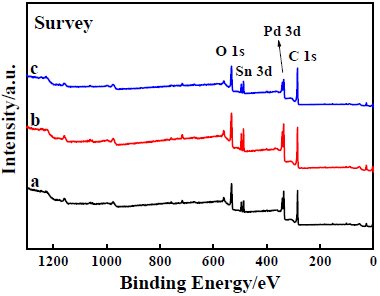
XPS spectra of all prepared catalysts are shown in the serial figures of Fig. 4. As shown in figure a, the typical binding peaks assigned to the elements of O, Sn, Pd and C are explicitly exhibited, being in accordance well with the EDS results (figure a of Fig. 2). In the C1s XPS spectra (figure b of Fig. 4), the binding peaks emerging at 284.8, 286.7 and 288.7 eV were, respectively, assigned to the C=C sp2, C-O and C=O groups of the carbon material [42]. The intensity of the peak at 284.8 eV was significantly higher than that of other two peaks, implying that carbon materials mainly existed in the form of sp2 carbon [28]. As for the O1s XPS spectra (figure c of Fig. 4), the binding energy (BE) peaks at 531.4 eV and 533.6 eV were originated from the O1s of C-O [43], C-OH/HO-C=O [43], respectively. In the case of catalyst a and b, a very small BE peak appeared at about 535.9 eV, which was due to the presence of C-O=O [44].
(a)
(b)
(c)
(d)
(e)
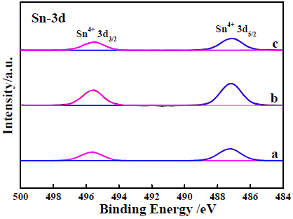
Figure 4. XPS survey spectra of catalyst a, b and c. (a) Wide scan XPS survey spectra; (b) XPS spectra for C1s; (c) XPS spectra for O1s; (d) XPS spectra for Pd 3d; (e) XPS spectra for Sn 3d
For the Pd 3d XPS spectra (figure d of Fig. 4), the BE peaks at 335.7 eV, 337.1 eV, 340.8 eV and 342.8eV were assigned to the 3d orbit of Pd0 (3d5/2), Pd2+ (3d5/2), Pd0 (3d3/2) and Pd2+ (3d3/2) [45], respectively. The peak intensity ratios of Pd0 (3d5/2) (at 335.7 eV) to that of Pd2+(3d5/2) (at 337.1 eV) were roughly calculated to be 0.69, 1.02 and 0.68 for catalyst a, b and c, respectively. That is, under the same loading amount, the content of the metallic Pd in catalyst b was evidently higher than that of other two catalysts, which was very profitable to the electrocatalytic activity improvement of a Pd based composite catalyst. In the Sn 3d XPS spectra (figure e of Fig. 4), the BE peaks at 487.1 and 495.5 eV were respectively assigned to the 3d orbit of Sn4+ (3d5/2) and Sn4+ (3d3/2), confirming the existence of Sn4+ in the final catalysts [46]. Hence, it was rational to think that the added starting material of SnO was totally chemically oxidized to be SnO2 after the whole preparation process. Summarily, metallic Pd, PdO, SnO2 and carbon material as the main substances existed in all prepared catalysts.
3.2 Surface morphology observation
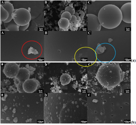
The surface morphologies of all prepared catalyst carriers are given in figure a of Fig. 5. In the SEM images with a scale of 1 μm, except for some irregular particles, several large spheres with a smooth surface were seen clearly in all resultant SEM images. These large spheres were the carbon spheres on the basis of the previous work concerning the preparation of carbon spheres (denoted as CS) [28]. The diameters of the CSs were measured roughly to be 4.9 μm, 2.6 μm and 6.6 μm for catalyst carrier A, B and C, respectively. While, for the SEM images with a scale of 100 nm, particles with rather different shapes and sizes were observed to be decorated on the surface the large CSs. A large particle that was constructed by many nanoparticles was seen distinctly on the surface of the large CSs of catalyst carrier A. An aggregate piled up by several large particles appeared in catalyst carrier C. For catalyst carrier B, several particles were seen on the surface of the large CSs. It was because of this, all prepared catalyst carriers were the CSs decorated with particles.
Figure 5. (a) SEM images for all prepared catalyst carriers. Image A, B and C corresponded to catalyst carrier A, B and C; (b) SEM images for all prepared catalysts. Image a, b and c corresponded to catalyst a, b and c. The scales of SEM images in the upper part and lower part were 1 μm and 100 nm, respectively
The surface morphologies of all prepared catalysts are provided in figure b of Fig. 5. In this case, besides the large CS, a lot of small particles appeared in all resultant SEM images. For the 1 μm scaled SEM images, besides some irregular particles, several large CSs were displayed clearly. For catalyst a, large carbon spheres were connected together forming an huge aggregate, and many irregular small particles were attached on the surface of carbon spheres generating a burry surface. For catalyst b, besides one large carbon sphere, many particles with a size of about 0.15 μm were accumulated together generating several large aggregates. In the case of catalyst c, a large carbon sphere with a diameter of about 7.2 μm, which was decorated by many irregular small particles, was seen in the observation window. To further observe the surface morphology of the resultant CS, SEM images with a scale of 100 nm for all catalysts are also presented (lower part of figure b). For catalyst a, several irregular aggregates with a size ranging from 140 nm to 40 nm were observed on the surface of the CS. Interestingly, in the case of catalyst b, some nanoparticles with a uniform size close to 70 nm were evenly distributed on the surface of CS. While, for catalyst c (image c), several small aggregates that were piled up by much smaller particles were found to be anchored on the surface of CS. Interestingly, for catalyst c, some evident holes with an inside diameter of about 70 nm were viewed explicitly, which was probably due to the peeling off of the particles decorated on the surface of CS. Hence, the added quantity and the kinds of tin oxides in preparing the catalyst carriers were all critical factors, which could not only affect the surface morphology but also the particle size of the final catalysts. For catalyst a and b, the surface of CS was not flat, instead, it was densely covered by a large number of protuberances forming a bumpy surface. Evidently, the surface protuberance size of CS of catalyst c was the minimum one among all studied catalysts, showing a relatively smooth surface.
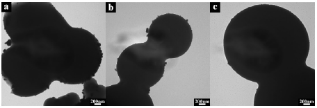
Figure 6. TEM images for all prepared catalysts. Image a, b and c corresponded to catalyst a, b and c.
TEM images of all prepared catalysts are given in Fig. 6. In each image, large black spheres were exhibited clearly, which strongly indicated that all prepared carbon spheres were carbon solid spheres (CSS). That is, the interior of CSS was fully filled with glucose-derived substances even after the air atmosphere calcination treatment (at 600℃ for 1 h). Besides, some irregular particles appeared at the boundary of all observed CSS, which effectively documented that some irregular particles were immobilized on the surfaces of CSS, being consistent with the SEM observation.
3.3 Electrocatalytic activities of all prepared catalysts towards EOR
To better compare the electrocatalytic activities of all prepared catalysts towards EOR, the CV curves of various catalysts coated GC electrodes, which were recorded in a solution of 1M KOH containing 1M ethanol, are collected in Fig. 7. For each catalyst coated GC electrode, two typical oxidation peaks were explicitly displayed in the testing potential range, suggesting that all prepared catalysts had an evident electrocatalytic activity towards EOR [47].
Figure 7. CV curves for the as-prepared catalyst modified GC electrode, which were recorded at 50 mV s-1 in an electrolyte solution containing 1M KOH and 1M ethanol. Curve a, b and c corresponded to the case of using electrode a, b and c
In general, the electro-oxidation peak appearing in the positive potential scanning (denoted as peak f) was resulted from the direct electrochemical oxidation of ethanol molecules, and the abnormal electro-oxidation peak appearing in the negative potential scanning (nominated as peak b) was originated from the electrochemical oxidation of the intermediates that were generated in the direct electrochemical oxidation of ethanol molecules (while producing peak f) [48]. As shown in Fig. 7, the peak current densities of the peak f and b were measured to be 18.9 and 23.6, 82.1 and 122.7, 28.9 and 36.9 mA cm-2 on catalyst a, b and c, respectively. It should be emphasized that the peak current densities of electrode a, b and c were all remarkably larger than the previously reported data measured on Pd/C (10.3 mA cm-2). Especially, the peak current density of electrode b were significantly higher than that recorded on Pd2Sn:P/C catalyst (41.2 mA cm-2) [49]. Above results strongly indicated that the electrocatalytic activities of all prepared catalysts toward EOR were superior to that of the previously reported catalysts. Evidently, catalyst b exhibited the maximum peak current density value among all examined catalysts, implying that the electrocatalytic activity of catalyst b toward EOR was superior to that of catalyst a and c. The ratios of the peak current density of the peak f to that of peak b were, respectively, roughly estimated to be 0.80, 0.67 and 0.78 in the case of using catalyst a, b and c. That is to say, as compared to the cases of using catalyst a and c, more amounts of EOR intermediates were electrochemically oxidized while using catalyst b. The total peak area (both peak f and peak b) of EOR on catalyst b was significantly larger than that of using catalyst a and c, which effectively indicated that more amount of C2H5OH molecules was electrochemically oxidized on catalyst b as compared to the case of using catalyst a and c, generating a satisfactory EOR electrocatalytic performance.
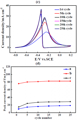
Figure 8. Successive CV curves, which were measured at the 1, 5, 10, 15, 20 and 25 cycles in 1M KOH containing 1M ethanol at 50 mV s-1, for various catalysts coated GC electrode. Figure a, b and c corresponded to the case of using catalyst a, b and c modified GC electrodes. The curves showing the relationship between the peak current density of peak f for EOR and the cycling number was illustrated in figure d. In figure d, curve a, b and c corresponded to the case of using electrode a, b and c
The successive CV curves of EOR on various catalysts coated GC electrodes are illustrated in the figures of Fig. 8 with an intention to study the cycling stability of EOR on each catalyst. To be noted, the CV curves in Fig. 8 were recorded at 1, 2, 5, 10, 15, 20 and 25 cycles. In figure a, for peak f and peak b, the peak current density gradually increased with increasing the cycling number, suggesting that catalyst a was reactivated in the successive potential cycling. In the case of catalyst b (figure b of Fig. 7), except for the first cycle, all other CV curves were almost overlapped, implying that the electrocatalytic activity of catalyst b had no evident variation during the whole cycling test, exhibiting a satisfied electro-catalysis performance consistency. The varying trend of the peak current density with cycling number for catalyst c (figure c of Fig. 8) was similar to that of catalyst a, i.e., the peak current density of peak f evidently increased with increasing the cycling number. The relationship between the peak current density of peak f and the cycling number for all prepared catalysts is plotted in figure d of Fig. 8. Apparently, in the total testing period, catalyst b showed the largest peak current density, for example, at the 20th cycle, the peak current density of peak f on catalyst a, b and c were 17.4, 82.3 and 28.1 mA cm-2, respectively, proving that catalyst b had the best electrocatalytic activity towards EOR among all prepared catalysts.
Figure 9. The CA curves measured in an electrolyte solution containing 1M KOH and 1M ethanol, in which the applied potential was fixed at -0.27 V. Curve a, b and c corresponded to the case of using electrode a, b and c
The electrocatalytic durability of all studied catalysts was examined by using CA (Fig. 9). On the basis of the previous work, the rapid drop of current density in the initial stage of the CA curve was generally ascribed to the fast variation of the electric charge of the double electric layer appearing on the working electrode surface, which was usually called as capacitive current, and the gentle straight line appearing in the CA curve was commonly resulted from the direct electro- oxidation of ethanol molecules or the intermediates formed during the direct EOR process, which was mostly nominated as faradic current or polarized current [50]. Evidently, catalyst b showed the largest faradic current density in the whole testing period, presenting a satisfied electrocatalytic durability. Especially, even after 7200 s, the current density of EOR on catalyst b was still retained to be 7.9 mA cm-2, which was significantly higher than that of case using catalyst a (0.1 mA cm-2) and catalyst c (3.2 mA cm-2). The sequence of the electrocatalytic durability for all studied catalysts displayed in Fig. 9 was consistent well with that order shown in Fig. 7, namely, following the decreasing order, catalyst b>c>a.
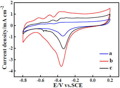
Figure 10. CV curves for electrode a, b and c, which were measured on various catalysts coated GC electrodes in 1M KOH at 50 mV s-1. Curve a, b and c corresponded to electrode a, b and c
The CV curves of all prepared catalysts were also measured in 1 M KOH solution desiring to further reveal the electrocatalytic mechanism of all studied catalysts towards EOR (Fig. 10). The shape of all the CV curves was very similar to that of the CV curve measured on the pure Pd electrode [51], which strongly indicated that the metallic Pd was still the main substance of all prepared catalysts to electrochemically catalyze the EOR process. Through comparing with previous work concerning the CV performance of pure Pd electrode in KOH solution [51], it was concluded that the electrochemical reduction peak centered about -0.35V was attributed to the electro-reduction of PdO to metallic Pd, i.e., PdO + H2O + 2e-→Pd + 2OH- [51], which was denoted as PdO/Pd peak for simplicity. That is to say, prior to the EOR process, all the PdO molecules have been electrochemically reduced to be metallic Pd since the EOR started at about -0.7V on all prepared catalysts (as shown in Fig. 7). The sequence of the peak current densities for the PdO/Pd peaks was the following increasing order, namely, catalyst a˂c˂b, which was consistent well with the electrocatalytic performance order shown in Fig. 7 and Fig. 9. The largest CV area of the PdO/Pd peak was exhibited by catalyst b, suggesting that more amount of metallic Pd were electrochemically produced on catalyst b prior to the EOR process. To provide a quantitative comparison of the active area for all studied catalysts, the electrochemical surface area (ECSA) of each catalyst was approximately calculated using the following equation (1) [52], namely,
$\mathrm{ECSA}=\mathrm{Q}_{\mathrm{pdo}} /(\mathrm{m} \times \mathrm{C})$ (1)
In above equation, QPdO was the electric charge used for the electrochemical reduction of PdO monolayer, which was roughly equal to the ratio of the CV peak area of PdO/Pd to the potential scanning rate. And, m was the amount of the metallic Pd in each catalyst, C was a constant of 424 mC cm-2. After a careful calculation, the ECSA of catalyst a, b and c was determined to be 4.8 m2 gPd-1, 22.8 m2 gPd-1 and 13.0 m2 gPd-1, respectively. Encouragingly, the value of 22.8 m2 gPd-1 measured on catalyst b was much higher than the recently reported ECSA value (8.35 m2 gPd-1) measured on a Pd/NiO/Ti composite catalyst [53]. Therefore, all prepared catalysts, especially catalyst b, were thought to be promising electrocatalysts for EOR based fuel cells.
(a)
(b)
(c)
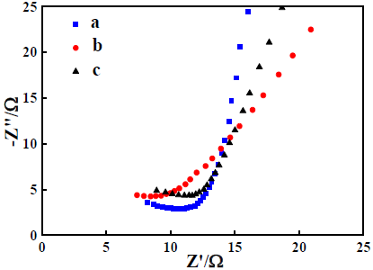
Figure 11. EIS results for electrode a, b and c, which were detected in an electrolyte containing 1M KOH and 1M ethanol. In all figures, curve a, b and c corresponded to the case of using electrode a, b and c. (a) Nyquist plots; (b) Bode plots; (c) Curves of the total impedance (Z) against frequency (f)
Results of EIS for all prepared catalysts are shown in the figures of Fig. 11. Curves in figure a are the Nyquist plots for all prepared catalysts, which were measured in the solution of 1M KOH containing 1M ethanol. Generally, for an electrochemical reaction, its Nyquist plot consisted of a semicircle in the higher frequency range (The diameter of the semicircle was equal to the charge transfer resistance (Rct)) and a 45° line in the lower frequency region [54]. In this case, each Nyquist plot comprised a straight line in the higher frequency range and a sloped line in the lower frequency region. That is, the Rct value of EOR on the studied catalyst was too small to be presented, which could only be attributed to the presence of carbon solid spheres in all prepared catalysts. In the Bode plots of all prepared catalysts (figure b of Fig. 11), one huge symmetrical peak was distinctly displayed in the total frequency region, which effectively indicated that the microstructures of all prepared catalysts were close to each other. The relationship between the total resistance and the applied frequency for all prepared catalysts are given in figure c of Fig. 11. The total resistance values of all prepared catalysts were almost identical when the frequency was higher than 100 Hz, which indirectly indicated that the main microstructures of all prepared catalyst were very similar to each other, i.e., showing a structure of carbon solid sphere anchored by many nanoparticles.
In summary, the relatively higher content of metallic Pd as compared to Pd2+, the uniform particle size and the largest CV peak area were analyzed to be the main reasons rendering catalyst b the best EOR electrocatalytic activity among all prepared catalysts. Preparing a novel catalyst of SnO2-CSS supported Pd based composite EOR catalyst using PdO·H2O and tin oxides as the starting materials was the major contribution of this preliminary work, which was very helpful to the further development of Pd based EOR electrocatalysts.
For the first time, a novel catalyst carrier of SnO2-CSS was prepared via a hydrothermal process assisted calcination method, and then, the as-prepared catalyst carrier supported Pd based composite catalysts (Pd/SnO2-CSS) were fabricated through using a hydrothermal method. The surface morphologies of all prepared catalysts were observed by using SEM, revealing that a large number of particles with various sizes were anchored on the surface of the prepared CSS. The chemical compositions of all prepared catalysts were mainly analyzed by using XRD and XPS, showing that metallic Pd, PdO, SnO2 and carbon material were the main substances of all prepared catalysts. More importantly, as indicated by CV and CA results, all prepared catalysts had an evident electrocatalytic activity towards EOR. Especially, in the CA test, the polarized current density of EOR on catalyst b was maintained to be as high as 7.9 mA cm-2 even after 7200 s, suggesting that catalyst b was a promising catalyst to substitute the current Pd based catalyst. In this work, besides the elements of Pd, C, O and Sn, no other elements were introduced into the preparation system, which was an important merit of the present work as compared to the previously published works regarding the preparation of Pd and Sn composite catalysts for EOR. This strategy can be employed to prepare CSS decorated with other metal oxides so as to promote the development of Pd based binary or ternary EOR electrocatalysts.
The work was supported by the Innovation ability improvement project of Hebei province (225A4402D) and Graduate student innovation ability training program of Hebei Normal University (CXZZSS2022060) and The Innovation Capability Improvement Plan Project of Hebei Province (22567604H).
[1] Wang Y, Zheng M, Li Y, Ye C, Chen J, Ye J, Zhang Q, Li J, Zhou Z, Fu XZ, Wang J, Sun SG, Wang D (2022) P-d orbital hybridization induced by a monodispersed Ga site on a Pt3Mn nanocatalyst boosts ethanol electrooxidation. Angew Chem Int Ed 61:e202115735. https://doi.org/10.1002/anie.202115735.
[2] Chen W, Luo S, Sun M, Wu X, Zhou Y, Liao Y, Tang M, Fan X, Huang B, Quan Z (2022) High-entropy intermetallic PtRhBiSnSb nanoplates for highly efficient alcohol oxidation electrocatalysis. Adv Mater 34:2206276. https://doi.org/10.1002/adma.202206276
[3] Xiao F, Wang YC, Wu ZP, Chen G, Yang F, Zhu S, Siddharth K, Kong Z, Lu A, Li JC, Zhong CJ, Zhou ZY, Shao M (2021) Recent advances in electrocatalysts for proton exchange membrane fuel cells and alkaline membrane fuel cells. Adv Mater 33:2006292. https://doi.org/10.1002/adma.202006292.
[4] Wu Y, Zhou H, Zhang A, Zhao L (2022) Numerical simulation of methanol crossover in flowing electrolyte- direct methanol fuel cell. J Power Sources 519:230801. https://doi.org/10.1016/j.jpowsour.2021.230801.
[5] Sandoval-González A, Gamboa S.A (2018) Analysis of redox reactions on Pt-Sn based nano-catalysts for direct methanol fuel cell applications. J New Mater Electrochem Syst. 21(1):21-28. https://doi.org/10.14447/jnmes.v21i1.517.
[6] Carbajal F.G, García M.A, Gamboa S.A (2018) Study of ethanol electrooxidation reaction at room temperature on nanometric Pt-Ru, Pt-Sn and Pt-Ru-Sn in direct alcohol fuel cells. J New Mater Electrochem Syst. 21(1):43-49. https://doi.org/10.14447/jnmes.v21i1.522.
[7] Ipadeola AK, Eid K, Lebechi AK, Abdullah AM, Ozoemen KI (2022) Porous multi-metallic Pt-based nanostructures as efficient electrocatalysts for ethanol oxidation: a mini-review. Electrochem Commun 140:107330. https://doi.org/10.1016/j.elecom.2022.107330.
[8] Liu L, Jamal R, Abdiryim T, Liu X, Zou D, Liu H, Song Y (2022) Preparation of Co/N-CNT@poly(3,4- ethylenedioxythiophene)-NH2/Pt as an efficient catalyst for ethanol oxidation reaction. Appl Surf Sci 591:153139. https://doi.org/10.1016/j.apsusc.2022.153139.
[9] Wang Z, Bo K, Wang Y, Wang Y (2022) Eutectic salts assisted synthesis of MOF-derived porous carbon as Pt- Sn catalyst support for ethanol oxidation reaction. In J Hydrog Energy 47:18285-18293. https://doi.org/10.1016/j.ijhydene.2022.04.030.
[10] Ramos-Sanchez V.H, Brito-Picciotto D, Gomez-Vargas R, Chavez-Flores D, Valenzuela E (2014) Carbon supported Au-Pd-PdO with low metal loading for electro-oxidation of methanol in alkaline medium. J New Mater Electrochem Syst. 17(3):133-138. https://doi.org/10.14447/jnmes.v17i3.401.
[11] Ji L, Che H, Qian N, Li J, Luo S, Li X, Wu X, Xu Q, Gong X, Cui X, Zhang H, Yang D (2023) Unconventional s-p-d hybridization in modulating frontier orbitals of carbonaceous radicals on PdBi nanosheets for efficient ethanol electrooxidation. Appl Catal B 328:122521. https://doi.org/10.1016/j.apcatb.2023.122521.
[12] Xu B, Liu T, Liang X, Dou W, Geng H, Yu Z, Li Y, Zhang Y, Shao Q, Fan J, Huang X (2022) Pd-Sb rhombohedra with an unconventional rhombohedral phase as a trifunctional electrocatalyst. Adv Mater 34:2206528. https://doi.org/10.1002/adma.202206528.
[13] Tang C, He Z, Liu Y, He X, Chen G, Xie C, Huang J (2023) AuPd nanoporous dendrites: high electrocatalytic activity and surface plasmon-enhanced stability for ethanol electrooxidation. Chem Eng J 453:139962. https://doi.org/10.1016/j.cej.2022.139962.
[14] Lestarini DT, Hong JW (2023) Intermetallic Pd3Pb nanobranches with low-coordinated surface atoms for highly efficient ethanol oxidation reaction. Appl Surf Sci 610:155311. https://doi.org/10.1016/j.apsusc.2022.155311.
[15] Lv H, Sun L, Wang Y, Liu S, Liu B (2022) Highly curved, quasi-single-crystalline mesoporous metal nanoplates promote C-C bond cleavage in ethanol oxidation electrocatalysis. Adv Mater 34:2203612. https://doi.org/10.1002/adma.202203612.
[16] Li F, Xue Q, Ma G, Li S, Hu M, Yao H, Wang X, Chen Y (2020) Formic acid decomposition-inhibited intermetallic Pd3Sn2 nanonetworks for efficient formic acid electrooxidation. J Power Sources 450:227615. https://doi.org/10.1016/j.jpowsour.2019.227615.
[17] Zhou M, Liu J, Ling C, Ge Y, Chen B, Tan C, Fan Z, Huang J, Chen J, Liu Z, Huang Z, Ge J, Cheng H, Chen Y, Dai L, Yin P, Zhang X, Yun Q, Wang J, Zhang H (2022) Synthesis of Pd3Sn and PdCuSn nanorods with L12 phase for highly efficient electrocatalytic ethanol oxidation. Adv Mater 34:2106115. https://doi.org/10.1002/adma.202106115.
[18] Liu D, Tian S, Zhang Y, Hu C, Liu H, Chen D, Xu L, Yang J (2023) Ultrafine SnPd nanoalloys promise high- efficiency electrocatalysis for ethanol oxidation and oxygen reduction. ACS Appl Energy Mater 6:1459- 1466. https://doi.org/10.1021/acsaem.2c03355.
[19] Selepe CT, Gwebu SS, Matthews T, Mashola TA, Sikeyi LL, Zikhali M, Maxakato NW (2021) Effect of Sn doping on Pd electro-catalysts for enhanced electro- catalytic activity towards methanol and ethanol electro- oxidation in direct alcohol fuel cells. Nanomaterials 11:2725. https://doi.org/10.3390/nano11102725.
[20] Lović JD, Pantović SE, Rakoč ević LZ, Ignjatović NL, Dimitrijević SB, Nikolić ND (2023) A novel two-step electrochemical deposition method for Sn-Pd electrocatalyst synthesis for a potential application in direct ethanol fuel cells. Processes 11:120. https://doi.org/10.3390/pr11010120.
[21] Wang X, Fan W, Zhang C, Chi M, Zhu A, Zhang Q, Liu Q (2019) Well-dispersed Pd-Sn nanocatalyst anchored on TiO2 nanosheets with enhanced activity and durability for ethanol electarooxidation. Electrochim Acta 320:134588. https://doi.org/10.1016/j.electacta.2019.134588.
[22] Adam AMM, Zhu A, Ning L, Deng M, Zhang Q, Liu Q (2019) Carbon supported PdSn nanocatalysts with enhanced performance for ethanol electrooxidation in alkaline medium. Int J Hydrog Energy 44:20368-20378. https://doi.org/10.1016/j.ijhydene.2019.06.013.
[23] Zhou X, Ma Y, Ge Y, Zhu S, Cui Y, Chen B, Liao L, Yun Q, He Z, Long H, Li L, Huang B, Luo Q, Zhai L, Wang X, Bai L, Wang G, Guan Z, Chen Y, Lee CS, Wang J, Ling C, Shao M, Fan Z, Zhang H (2022) Preparation of Au@Pd core-shell nanorods with fcc- 2H-fcc heterophase for highly efficient electrocatalytic alcohol oxidation. J Am Chem Soc 144:547-555. https://doi.org/10.1021/jacs.1c11313.
[24] Zeng T, Zheng L, Chen H, Wang Y, Ling M, Sun S, Zhang F, Yuan W, Zhang LY (2023) One-pot controllable epitaxial growth of Pd-based heterostructures for enhanced formic acid oxidation. Colloids Surf A Physicochem Eng Asp 656:130358. https://doi.org/10.1016/j.colsurfa.2022.130358
[25] Hameed RMA, Fahim AE, Allam NK (2020) Tin oxide as a promoter for copper@palladium nanoparticles on graphene sheets during ethanol electro-oxidation in NaOH solution. J Mol Liq 297:111816. https://doi.org/10.1016/j.molliq.2019.111816.
[26] Konwar D, Basumatary P, Lee U, Yoon YS (2021) P- doped SnFe nanocubes decorated with PdFe alloy nanoparticles for ethanol fuel cells. J Mater Chem A 9:10685-10694. https://doi.org/10.1039/D0TA12120G.
[27] Wang Q, Li H, Chen L, Huang X (2001) Monodispersed hard carbon spherules with uniform nanopores. Carbon 39:2211-2214. https://doi.org/10.1016/S0008- 6223(01)00040-9.
[28] Sun X, Li Y (2004) Colloidal carbon spheres and their core/shell structures with noble-metal nanoparticles. Angew Chem Int Ed 43:597-601. https://doi.org/10.1002/ange.200352386
[29] Yan Z, Hu Z, Chen C, Meng H, Shen PK, Ji H, Meng Y (2010) Hollow carbon hemispheres supported palladium electrocatalyst at improved performance for alcohol oxidation. J Power Sources 195:7146-7151. https://doi.org/10.1016/j.jpowsour.2010.06.014.
[30] Bai Z, Luo J, Ming D, Wang C, Xu H, Ye W (2020) High active and durable N-doped carbon spheres- supported flowerlike PtPd nanoparticles for electrochemical oxidation of liquid alcohols. Electrochim Acta 356:136794. https://doi.org/10.1016/j.electacta.2020.136794.
[31] Naveen MH, Huang Y, Kantharajappa SB, Seo KD, Park DS, Shim YB (2021) Enhanced electrocatalytic activities of in situ produced Pd/S/N-doped carbon in oxygen reduction and hydrogen evolution reactions. ACS Appl Energy Mater 4:575-585. https://doi.org/10.1021/acsaem.0c02461.
[32] Zhou Y, Li L, Liu Y, Wang H, Feng Z, Feng F, Zhang Q, Liu W, Han W, Lu C, Li X (2022) Palladium nanoparticles inset into the carbon sphere with robust acid resistance for selective hydrogenation of chloronitrobenzene. Ind Eng Chem Res 61:4310-4319. https://doi.org/10.1021/acs.iecr.1c04983.
[33] Ma X, Xiao H, Gao Y, Zhao M, Zhang L, Zhang J, Jia J, Wu H (2023) Enhancement of pore confinement caused by the mosaic structure on Ru nanoparticles for pH-universal hydrogen evolution reaction. J Mater Chem A 11:3524. https://doi.org/10.1039/D2TA09167D.
[34] Cao J, Qin C, Wang Y (2017) Synthesis of g-C3N4 nanosheets decorated flower-like tin oxide composites and their improved ethanol gas sensing properties. J Alloys Compd 728 : 1101-1109. https://doi.org/10.1016/j.jallcom.2017.09.073.
[35] Yang H, Li S, Shen S, Jin Z, Jin J, Ma J (2019) Unraveling the cooperative synergy of palladium/tin oxide/aniline-functionalized carbon nanotubes enabled by layer-by-layer synthetic strategy for ethanol electrooxidation. ACS Sustain Chem Eng 7:10008- 10015. https://doi.org/10.1021/acssuschemeng.9b01197.
[36] Maiyalagan T, Scott K (2010) Performance of carbon nanofiber supported Pd–Ni catalysts for electro- oxidation of ethanol in alkaline medium. J Power Sources 195:5246-5251.https://doi.org/10.1016/j.jpowsour.2010.03.022.
[37] Pinheiro VS, Souza FM, Gentil TC, Nascimento AN, Böhnstedt P, Parreira LS, Paz EC, Hammer P, Sairre MI, Batista BL, Santos MC (2020) Sn-containing electrocatalysts with a reduced amount of palladium for alkaline direct ethanol fuel cell applications. Renew Energ 158:49-63. https://doi.org/10.1016/j.renene.2020.05.050.
[38] Ding K, Li Y, Zhao Y, Liu L, Gu H, Liu L, Qiu S, He C, Liu J, Wang Q, Guo Z (2014) Dry-grinding synthesized multi-walled carbon nanotubes supported PdO catalyst for ethanol oxidation reaction. Electrochim Acta 149:186-192. https://doi.org/10.1016/j.electacta.2014.10.107.
[39] Zhang C, Hatzell KB, Boota M, Dyatkin B, Beidaghi M, Long D, Qiao W, Kumbur EC, Gogotsi Y (2014) Highly porous carbon spheres for electrochemical capacitors and capacitive flowable suspension electrodes. Carbon 77:155-164. https://doi.org/10.1016/j.carbon.2014.05.017.
[40] Wu J, Jin C, Yang Z, Tian J, Yang R (2015) Synthesis of phosphorus-doped carbon hollow spheres as efficient metal-free electrocatalysts for oxygen reduction. Carbon 82:562-571. https://doi.org/10.1016/j.carbon.2014.11.008.
[41] Taheri M, Ghiaci M, Shchukarev A (2108) A comparison between two Pd-Ni catalysts supported on two different supports toward Suzuki-Miyaura coupling reaction. Appl Organomet Chem 32:4338. https://doi.org/10.1002/aoc.4338.
[42] Ma T, Zhao X, Cao Y, Wu Y, Zhou Y, Chen H (2020) L-histidine-functionalized carbon black pigment with zwitterionic property: preparation, characterization and application. Dyes Pigm 173:107992. https://doi.org/10.1016/j.dyepig.2019.107992.
[43] Huang Z, Shi L, Muhammad Y, Li L (2021) Effect of ionic liquid assisted hydrothermal carbonization on the properties and gasification reactivity of hydrochar derived from eucalyptus. J Colloid Interface Sci 586:423-432. https://doi.org/10.1016/j.jcis.2020.10.106.
[44] Fan Y, Liu PF, Huang ZY, Jiang TW, Yao KL, Han R (2015) Porous hollow carbon spheres for electrode material of supercapacitors and support material of dendritic Pt electrocatalys. J Power Sources 280:30- 38. https://doi.org/10.1016/j.jpowsour.2015.01.096.
[45] Gai HY, Wang XK, Huang MH (2021) Catalytic activity analysis of uniform palladium nanoparticles anchored on nitrogen-doped mesoporous carbon spheres for oxygen reduction reaction. Chinese J Anal Chem 49:e21096-e21103. https://doi.org/10.1016/S1872-2040(21)60104-4.
[46] Javanmardi S, Nasresfahani Sh, Sheikhi MH (2019) Facile synthesis of PdO/SnO2/CuO nanocomposite with enhanced carbon monoxide gas sensing performance at low operating temperature. Mater Res Bull 118:110496. https://doi.org/10.1016/j.materresbull.2019.110496.
[47] Nguyen MTX, Nguyen MK, Pham PTT, Huynh HKP, Pham HH, Vo CC, Nguyen ST (2021) High- performance Pd-coated Ni nanowire electrocatalysts for alkaline direct ethanol fuel cells. J Electroanal Chem 888:115180. https://doi.org/10.1016/j.jelechem.2021.115180.
[48] Yu K, Lin Y, Fan J, Li Q, Shi P, Xu Q, Min Y (2019) Ternary N, S, and P-doped hollow carbon spheres derived from polyphosphazene as Pd supports for ethanol oxidation reaction. Catalyst 9:114. https://doi.org/10.3390/catal9020114.
[49] Yu X, Liu J, Li J, Luo Z, Zuo Y, Xing C, Llorca J, Nasiou D, Arbiol J, Pan K, Kleinhanns T, Xie Y, Cabot A (2020) Phosphorous incorporation in Pd 2 Sn alloys for electrocatalytic ethanol oxidation, Nano Energy 77: 105116. https://doi.org/10.1016/j.nanoen.2020.105116.
[50] Ding K, Yang G, Wei S, Mavinakuli P, Guo Z (2010) Cyclic voltammetric preparation of palladium nanoparticles for ethanol oxidation reaction. Ind Eng Chem Res 49:11415-11420. https://doi.org/10.1021/ie101553f.
[51] Liang ZX, Zhao TS, Xu JB, Zhu LD (2009) Mechanism study of the ethanol oxidation reaction on palladium in alkaline media. Electrochim Acta 54:2203-2208. https://doi.org/10.1016/j.electacta.2008.10.034.
[52] Cui Z, Hu J, Jiang X, Zhang D, Fang C (2021) Asymmetric Au/(PdAg alloy) nano-allium giganteums for their enhanced electrocatalytic performances to ethanol oxidation reaction. J Alloys Compd 855:157385. https://doi.org/10.1016/j.jallcom.2020.157385.
[53] Mozafari V, Parsa JB (2020) Promoted electrocatalytic performance of palladium nanoparticles using doped- NiO supporting materials toward ethanol electro- oxidation in alkaline media. Int J Hydrog Energy 45:28847-28859. https://doi.org/10.1016/j.ijhydene.2020.07.276.
[54] Ding K, Jia Z, Wang Q, He X, Tian N, Tong R, Wang X (2001) Electrochemical behavior of the self-assembled membrane formed by calmodulin (CaM) on a Au substrate. J Electroanal Chem 513:67-71. https://doi.org/10.1016/S0022-0728(01)00576-9.